Note: Descriptions are shown in the official language in which they were submitted.
CA 02477342 2004-08-12
IMPROVED SEALING GASKET WITH FLEXIBLE STOPPER
BACKGROUND AND SUMMARY OF THE INVENTION
[0001' The invention relates to a gasket for sealing between opposed mating
surfaces
of two or more members adapted to be forcibly mated together and to clamp the
sealing gasket
therebetween. More particularly, in a preferred form, the invention relates to
such gaskets
preferably having a single-layer carrier with unique embossments and a
flexible stopper portion.
[0002 Conventional gaskets, such as those used to seal between a cylinder head
and
cylinder block of an internal combustion engine, include two or more carrier
members, such as
those composed of spring steel, having various embossments to achieve proper
sealing as well as
the recovery needed to accommodate dynamic lifting of the cylinder head or
other relative
movement between the head and block. Such gaskets frequently include a
stopper, which is an
additional thin strip of metal or other material having a high stiffness. The
stopper is located
adjacent or near the combustion opening of the gasket in order to distribute
sufficient load
around the combustion opening area to properly seal and to prevent over-
compression of
adjacent combustion sealing embossments. In such constructions, the stopper is
typically welded
onto the carrier or formed from a folded-over portion of the carrier around
the circumference of
the combustion opening. In these designs, the stopper acts as the primary
seal, with one or more
other embossments acting as a secondary seal.
(0003, Although performing relatively well; such prior art constructions often
suffer
from certain disadvantages caused by the high rigidity of the stopper, such as
high bore
distortion, cylinder liner recessing, and inadequate accommodation of dynamic
head lifting.
Such disadvantages are frequently aggravated by the location of such highly
rigid stoppers at or
closely adjacent the combustion opening of the gasket, the cylinder head and
the cylinder block.
[0004, In order to improve upon such gasket designs and to address the
disadvantages
of gaskets of the type discussed above, as well as others, the present
invention seeks to reduce
bore distortion, to reduce liner recession, and to accommodate greater dynamic
head lifting while
more evenly distributing loads circumferentially about the combustion opening.
In addition,
since the preferred form of a gasket according to the invention has a lower-
cost single layer
carrier, it significantly reduces load loss resulting from the greater amount
of creep caused by
multiple layer constructions, as well as eliminating misalignment between
multiple layers,
CA 02477342 2004-08-12
tolerance stack up among multiple layers and associated load variations. A
preferred form of the
inventive gasket allows for carrier embossments that are preselected to have a
desired relative
flexibility, that provides greater capability to follow relative motion
between the members being
sealed, and that increases the gasket's ability to accommodate rough mating
surfaces of the
members over that of prior art multiple layer gaskets. It should be noted that
gaskets constructed
according to the present invention are applicable in a variety of cylinder
head and cylinder block
applications, such as those found in internal combustion engines or gas
compressors, for
example, as well as in intake or exhaust manifold sealing, fuel cell component
sealing and
numerous other automotive or non-automotive industrial applications.
[0005] The present invention provides an improved gasket for sealing between
opposed mating surfaces of two or more members having openings therein and
that are adapted
to be forcibly mated together, continuously or at least intermittently, to
clamp the gasket
therebetween, thus sealing around such openings, which are laterally aligned
for longitudinal
communication with each other. A gasket according to the present invention
includes a carrier
having first and second laterally extending sides or surfaces defining a
longitudinal thickness
therebetween. The carrier includes a gasket opening (as well as other coolant,
lubricant, fastener
or other openings, as required in a given application), with the gasket
opening being adapted to
be laterally aligned in longitudinal communication with the openings in the
mating surface of the
members when the gasket is clamped between the mated members. The preferred
carrier is
resiliently flexible in the longitudinal direction, but is relatively rigid in
comparison to other
elements of the gasket. A resilient sealing material that is substantially
more flexible than the
carrier material is disposed on at least portions of the laterally extending
sides of the carrier for
sealingly engaging the mated surfaces of the members at least adjacent their
openings when the
gasket is clamped between the mated members.
[0006] The carrier preferably includes a longitudinally flexible inner sealing
portion
disposed laterally adjacent the gasket opening with the inner sealing portion
being longitudinally
offset relative to the remainder of said carrier portion (or relative to an
intermediate carrier
portion located laterally outward of the inner sealing portion). The inner
sealing portion is
preferably offset in a longitudinal direction toward a first of the mating
surfaces of the members
when the gasket is being clamped therebetween and can be formed by way of
embossing the
2
CA 02477342 2004-08-12
relatively rigid (but still resiliently flexible) carrier, as well as by way
of other forming methods
or devices known to those skilled in the art. The inner sealing portion
preferably includes the
above-mentioned resilient sealing material disposed on at least portions of
its laterally-extending
sides for sealing engagement with the mating surfaces of 'the members when the
gasket is
clamped therebetween. These carrier features can be formed as embossments, for
example,
either before or after application of the resilient sealing material.
[0007] The preferred carrier also includes a longitudinally flexible stopper
portion
spaced laterally outwardly, away from the gasket opening so that the inner
sealing portion and
the flexible stopper portion are on opposite lateral sides of the above-
mentioned the intermediate
portion, or at least so that the flexible stopper portion is laterally outward
relative to the inner
sealing portion (i.e., with or without the intermediate carrier portion). The
preferred flexible
stopper portion is longitudinally convex relative to the remainder of the
carrier (or relative to the
intermediate carrier portion) on a side of the flexible stopper oriented
toward one of the mating
surfaces and is longitudinally concave relative to the remainder of the
carrier (or relative to the
intermediate carrier portion) on an opposite side of the flexible stopper
oriented toward another
of the mating surfaces of the members. The stopper, which can have a generally
trapezoidal
shape, for example, thus flexibly and resiliently limits the amount of
longitudinal compression of
the inner sealing portion but is typically less flexible than the inner
sealing portion. The inner
sealing portion is thus maintained in sealing engagement with the mating
surfaces of both of the
members during any relative movement therebetween when the members are mated
together.
[0008] In a preferred form of the invention, the inner sealing portion is
longitudinally
offset to an extent greater than the extent of the longitudinal convexity of
the flexible stopper so
as to assure deflection of the inner sealing portion prior to compression of
the flexible stopper.
In addition, the resilient sealing material is preferably disposed within, and
can completely fill or
at least partially fill the concave side of the flexible stopper member. In
specific applications,
however, it may be satisfactory to optionally omit the resilient sealing from
completely filling
the concave flexible stopper side altogether in any of the embodiments of the
invention.
[0009] In any of the gasket embodiments according to the present invention,
the inner
sealing portion can optionally be longitudinally offset in various
configurations, such as a
generally "Z-shaped" half embossment or a inclined or angled partially
embossed or bent
3
CA 02477342 2004-08-12
configuration, for example, as will become readily apparent to those skilled
in the art from the
drawings and from the following description and claims. Additionally, the
inner sealing portion
of the carrier, instead of being integrally formed by bending or by embossing
as part of the
carrier, can optionally be substantially separated from the remainder of the
carrier member but
interconnected and held in place by two or more connecting struts or by one or
more "living
hinges" formed of the resilient sealing material. Such living hinge or hinges
can be between any
pair of, or any combination of, the inner sealing portion, the intermediate
carrier portion and/or
the flexible stopper. Two or more flexible stoppers can also be optionally
included in some or all
of the embodiments of the invention, with such multiple flexible stoppers
facing in opposite
longitudinal directions, facing in the same longitudinal direction, or any
combination of such
orientations.
[0010] It should further be noted that gaskets according to the present
invention can
be advantageously used in a wide variety of applications, such as cylinder
head and block sealing
for internal combustion engines, gas compressors, or other devices having a
sealed cylinder
containing liquid or gaseous fluids, sealing intake, exhaust or other fluid
conveying manifold
applications, sealing between piping flanges, or sealingly isolating the
interior from the exterior
of housings or enclosures, for example. The present invention provides special
advantages
where relative movement can occur between the members being sealed, such as
that due to
thermal, mechanical or fluid conditions or environments presented by a
particular application.
Those skilled in the art will undoubtedly recognize many other advantageous
applications of
gaskets according to the present invention.
[0011] In addition, it should be emphasized that in any of the embodiments
discussed
herein, more than one layer of a gasket according to the present invention can
be used if desired
or needed in various applications. Such applications include those where
additional thickness is
needed to match the thickness of a previous gasket or gasket assembly that is
being replaced by a
gasket assembly according to the present invention, or where particular (e.g.,
increased) spring
rate, loading and/or deflection characteristics are desired or needed in
conjunction with the
flexible stopper characteristics and features discussed herein.
4
CA 02477342 2004-08-12
[0012 Additional objects, advantages, and features of the present invention
will
become apparent from the following description and the appended claims, taken
in conjunction
with the accompanying drawings.
BRIEF DESCRTPTION OF THE DRAWINGS
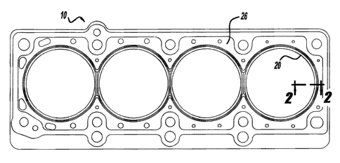
[0013, Figure I depicts one laterally-extending side of one exemplary
preferred
gasket according to the present invention, with the gasket being adapted fox
sealing between a
cylinder head and a cylinder block.
(0014 Figure 2 is a partial cross-sectional view, taken along line 2-2 of
Figure 1.
(0015 Figure 3 is a partial cross-sectional view, illustrating the exemplary
gasket of
Figure 1 in a partially compressed condition.
(0016 Figure 4 illustrates unloading curves for the exemplary gasket of Figure
l and
for a typical multiple layer prior art gasket, with load plotted against
relative deflection of the
mating members, in order to illustrate the invention's improved load retention
characteristics.
[001Tj Figure 5 is a partially exploded view, illustrating a typical multiple
layer prior
art gasket.
(0018 Figure 6 is a partially exploded view, similar to Figure 5, but
illustrating the
preferred, flexible but relatively rigid, single carrier member of Figure I
sandwiched between
two layers of the more highly flexible resilient sealing material.
(0019] Figures 7a and 7b illustrate an example of contact point stress values
in
opposite directions on opposite mating members during unloading between the
mating members
for a typical multiple layer prior art gasket.
(0020) Figures 8a and 8b are similar to Figures 7a and 7b, respectively, but
illustrating such contact point stress values in opposite directions on
opposite mating members
during unloading for an exemplary gasket according to the present invention
having a single
layer carrier.
[0021 Figure 9 is a partial cross-sectional view of an alternate gasket
according to
the present invention, which is similar to that of Figures I and 2, except
that the flexible stopper
portion is coated but not filled with resilient material on its concave side.
CA 02477342 2004-08-12
[0022] Figure 10 is a partial cross-sectional view, similar to that of Figures
2 and 9,
but illustrating yet another alternate embodiment of a gasket according to the
present invention,
wherein the flexible stopper portion has a generally serpentine, "S-shaped"
cross-sectional shape,
essentially forming multiple flexible stoppers, with the concave portions of
the flexible stopper
portion alternatively being merely coated with the resilient material or at
Least partially filled
with the resilient material.
[0023] Figure 11 is a partial cross-sectional view similar to that of Figures
2, 9 and
10, but illustrating still another alternate embodiment of a gasket according
to the present
invention, with the inner seal portion extending in a laterally and
longitudinally inclined or
angled direction, and with the flexible stopper portion being alternately
merely coated with the
resilient material or at least partially filled with the resilient material.
(0024] Figures 12a and 12b illustrate a partial perspective view and a partial
cross-
sectional view, respectively, of another alternate embodiment of the present
invention, wherein
the inner sealing portion of the carrier is substantially separated from the
remainder of the carrier
member but interconnected and held in place by two or more connecting struts.
(0025] Figures 13a and 13b are similar to those of Figures 12a and 12b,
respectively,
but illustrating yet another alternate embodiment of the present invention,
wherein the inner
sealing portion of the carrier member is separate from the remainder of the
carrier member, but
with the inner sealing portion and the intermediate carrier portion being
interconnected by one or
more "living hinge" sections of the resilient material.
(0026] Figure 14 is a partial schematic cross-section, conceptually
illustrating other
examples of other applications of the present invention.
(0027] Figure 15 is a partial cross-section similar to that of Figure 2, but
illustrating
the resilient sealing material covering only portions of the carrier member as
mentioned above.
[0028] Figures 16 through 20 diagrammatically illustrate still further
exemplary
embodiments, wherein one or more of the gasket constructions discussed above
(with or without
an accompanying shim member) may be desired in given applications.
6
CA 02477342 2004-08-12
DETAILED DESCRIPTION OF THE PREFERRED EMBODIMENTS
(0029] Figures 1 through 13 through 20 illustrate various embodiments of a
gasket
according to the present invention. For purposes of example, only, Figures 1
through 13 and 15
through 20 are primarily directed toward a cylinder head gasket for sealing
between mating
surfaces of a cylinder head and a cylinder block on an internal combustion
engine, gas
compressor, or other similarly configured device. It should be noted, however,
as will become
apparent to those skilled in the art from the following description and
claims, the principles of
the present invention illustrated in Figures 1 through 13 and 15 through 20
are equally applicable
to other devices used in the automotive and non-automotive industrial areas,
such as flanged
piping components, enclosure or housing seals, piping system manifold seals,
or other devices
where proper sealing and flexibility is desired between opposed mating
surfaces of two or more
members, as is illustrated conceptually in Figure 14.
[0030] Referring initially to Figures 1 through 4 and 6, one preferred
embodiment of
the invention is represented by an exemplary gasket 10 for sealing between a
mating member 12
and a mating member I4, which are adapted to be matingly clamped together,
with the gasket 10
therebetween, such as by bolts or other conventional clamping devices. The
mating members 12
and 14 have respective laterally-extending mating surfaces 13 and 15
surrounding respective
openings 16 and 18, which are configured for conducting fluids between the
members 12 and 14
generally in a longitudinal direction 22.
[003'1 ] The gasket 10 of Figure 1 includes a relatively rigid, but still
flexible, carrier
24, laterally-extending gasket sides 26 and 28, a complete coating (or at
least a localized coating)
of a much more flexible resilient sealing material 32, and a gasket opening 20
adapted to be
laterally aligned with the openings 16 and 18 of the members 12 and 14 for
longitudinal
communication therebetween. The gasket IO further includes a longitudinally-
offset inner
sealing portion 36, an intermediate portion 38, and a longitudinally offset
flexible stopper 40.
[0032] Preferably, exemplary the flexible stopper 40 (which can be
characterized as a
"full embossment") is Longitudinally offset to a lesser extent than the inner
sealing portion 36
(which can similarly be characterized as a "half embossment"). It is important
to emphasize that,
unlike the more rigid stoppers of prior art gaskets, the flexible stopper 40
is spaced away from
the gasket opening 20 (as well as from the mating member openings 16 and 18),
with the primary
7
CA 02477342 2004-08-12
sealing component of the gasket (i.e., the inner sealing portion 36) and the
intermediate portion
38 being between the flexible stopper 40 and the gasket opening 20. The
flexible stopper 40
preferably has a convex side 42 and a concave side 44, either of which can be
oriented toward
either of the members 12 or 14. The concave side 44 can optionally be merely
coated with the
resilient sealing material 32 or partially or completely filled with the
resilient sealing material 32.
Typically, although not necessarily in a given application, the inner sealing
portion 36 is more
flexible than the flexible stopper 40.
(0033] Examples of materials for the carrier 40 can include semi-rigid
synthetic or
natural materials, metals or non-metals, with one example being composed of
301 stainless
spring steel, full-hard, 0.3 mm thick (approximately 0.002 mm to 0.005 mm, or
even wider
ranges of thicknesses may be used in given applications). Lower hardnesses of
steel or other
metals can of course also be used if a reduction in spring force is desired in
a particular
application. However, such softer materials may, over time, exhibit a decrease
in recovery
performance during unloading conditions, such as those resulting from relative
movement
between the mating members. Other metals or metal alloys may also have
application in the
present invention, such as hardened carbon steel, inconel, titanium, or still
others known to those
skilled in the art.
(0034] Examples of materials for the resilient sealing material 32 in the
illustrated
example can include those that are applied to the carrier material prior to
forming the carrier
itself, those coated onto the Garner after it is formed, or even localized
coating only in desired
areas, such as those adjacent the gasket opening 20 or other areas adjacent
fluid openings (e.g.,
for lubricant, for cooling, etc.), bolt holes, or the like. Such resilient
sealing material 32 is
preferably on at least both sides of any or all of the inner sealing portion
36, the intermediate
portion 24, or the flexible stopper 40. If desired to be applied only in
localized areas of the
gasket 20, resilient sealing material 32 can be applied in a variety of
different ways, such as by
screen printing, for example. In this regard, it should also be noted that the
concave side 44 of
the flexible stopper 40 can be merely coated (as in the concave side 144 on
the stopper 140
shown in Figure 9) or partially or completely filled with the resilient
sealing material 32, either
locally or as part of a larger or even an overall coating of the carrier 24.
In one form of the
invention, the preferred resilient sealing material is FKM, having a thickness
of approximately
8
CA 02477342 2004-08-12
0.0002 inch to approximately 0.003 inch, although a much wider range of
thicknesses can be
used, as required or desirable in a particular application. Other resilient
and conformable
materials may also be suitable in any of a wide variety of applications, such
as nitrite or silicone,
for example.
[0035] In Figure 3, the gasket 10 is shown partially compressed between the
members 12 and 14. In this condition, as well as in other more fully
compressed conditions, the
inner sealing portion 36 typically deflects first and provides the primary
sealing about the
openings 16, 18 and 20. The flexible stopper 40, being typically les flexible
than the inner
sealing portion 36, limits the amount of compression or deflection of the
inner sealing portion
36, but it performs this function flexibly, unlike the much more rigid
stoppers of prior art
gaskets. This allows the gasket to provide more effective, repeatable and
reliable sealing
between the members 12 and 14, especially during lower load conditions, such
as those resulting
from relative movement between the members 12 and 14 due to compression,
combustion,
exhaust, or other varying pressures.
[0036] This advantage is further illustrated in Figure 4, wherein the
invention is
capable of higher (and thus more leak-proof j sealing loadings than is a
typical multiple layer
gasket of the prior art, such as that illustrated in Figure 5, for example,
throughout design
operating ranges. This advantageous comparison is also evident from Figures 7a
and 7b (prior
art) and Figures 8a and 8b, wherein the contact stresses on the opposed mating
surfaces of the
mating members (e.g., surfaces 13 and 15 on members 12 and 14, for example)
are graphically
represented at various location 1 through 8 on the mating surfaces.
[0037] Again referring to Figure 5, it is also important to note that such
multiple layer
prior art gaskets, such as the gasket 60, require sealing material on both
sides of each layer, with
the multiple and separately coated layers significantly adding to their cost,
as well as presenting
the other disadvantages discussed above.
[0038] Figures 10 through 14 illustrate other alternate constructions or
embodiments,
with the reference numerals in Figures 10 through 14 indicating similar or
corresponding
elements to those of Figures 1 through 9, but with two-hundred through six
hundred prefixes,
respectively.
9
CA 02477342 2004-08-12
(0039] Figure 10 illustrates a gasket 210, a generally serpentine flexible
stopper 240,
effectively forming a number of flexible stopper portions 240. In Figure 11,
the inner sealing
portion 336 is longitudinally offset in an inclined or angled direction.
Figures 12a and 12b
illustrate a separated inner sealing portion 436 interconnected with the
remainder of the gasket
410 and held in its proper position by one or more struts 446. Similarly, in
Figures 13a and 13b,
a separated inner sealing portion 536 is interconnected with the remainder of
the gasket 510 and
held in its proper position by one or more "living hinge" portions 536 of the
resilient sealing
material 532. It should be noted that this construction also allows for
different thicknesses of the
inner sealing portion 536 and the remainder of the gasket 510 (with either of
them being thicker
or thinner than the other) in order to obtain particular deformation and load
retention
characteristics in a given application.
(0040] Figure 14 schematically illustrates, in conceptual form, the use of a
gasket 610
according to the present invention in a wide variety of applications, with the
gasket 610 having
any or any combination of the features, shapes or characteristics discussed
above in connection
with Figures 1 through 13. The members 612 can be flanges or other portions of
any of
numerous devices or structures, such as intake, exhaust or other manifolds,
piping or other fluid-
conveying devices, gas compression or other high pressure constructions,
sealed housings or
enclosures, or other sealing applications known to those skilled in the art.
As mentioned above,
the invention is especially advantageous where relative movement can occur
between the
members being sealed, such as that caused by thermal, mechanical or fluid
conditions or
environments presented by a particular applications.
(0041] Figure 15 (taken along with the other figures) merely illustrates that
the
resilient sealing material 732 can optionally be included on all or selected
portions of the carrier
member 724 of the gasket 710.
(0042] In addition, exemplary Figures 16 through 20 illustrate that any of the
embodiments described herein can be used as part of a gasket assembly having
one, two or even
more of the gaskets 10 through 710 discussed above for sealing between at
least a pair of mating
surfaces. Such assemblies of the gaskets 810 through 1010, in Figures 16
through 18,
respectively, can be provided where additional thickness is needed. Such
assemblies of gaskets
810 through 1010, and even the single gasket applications 1110 and 1210 of
Figures 19 and 20,
CA 02477342 2004-08-12
can also be used to obtain desired spring rate, loading and/or deflection
characteristics (e.g.,
increases in some or all of these characteristics) while still gaining the
advantageous flexible
stopper characteristics discussed above. In this regard, it should also be
pointed out that either or
both sides of the gasket members 810 through 1210, or portions thereof, can
optionally be coated
with the resilient sealing materials mentioned above.
[0043 The shim members 870 through 1270 can optionally be included in any of
the
embodiments shown herein. The shim members can act as spacers and/or provide a
surface
against which the loading on the gaskets can be transferred so as to obtain
the intended spring
rate, loading and/or deflection characteristics. These intended effects might
not be obtained if
multiple gaskets were not separated by shim members and allowed to completely
or partially
"nest" within portions of each other, or otherwise incorrectly contact each
other, such as could
result in an application like that shown in Figure 18, for example.
[0044] As will now be apparent to those skilled in the art, the shims 870
through
1270 can be constructed either of relatively resilient sheet materials or of
relatively rigid sheet
materials and can be of widely-varying thicknesses in order to obtain the
above-mentioned
desired gasket assembly characteristics. Although the embodiments of Figures
16 and 17 can
advantageously include the shim members 870 and 970, respectively, it is
believed to be even
more likely that the embodiments of Figures 18 through 20 'would require the
inclusion of the
respective shim members 1070 through 1270. Like the gaskets 810 through 1210,
either or both
sides (or portions thereof) of the shim members 870 through 1270 can also
optionally be coated
with the above-described resilient sealing material if needed or desired in
particular applications.
[0045 The foregoing discussion discloses and describes merely exemplary
embodiments of the present invention for purposes of illustration only. One
skilled in the art will
readily recognize from such discussion, and from the accompanying drawings and
claims, that
various changes, modifications and variations can be made therein without
departing from the
spirit and scope of the invention as defined in the following claims.
11