Note: Descriptions are shown in the official language in which they were submitted.
CA 02477398 2004-08-12
BRAKING MONITORING SYSTEM
This application is based on the Provisional Serial No. 60/495,469 filed on
August
15, 2003.
BACKGROUND OF THE INVENTION
Thousands of vehicles are on the road every day, and most reported accidents
involve cars, trucks, bikes and even pedestrians. Alcohol is sometimes the
cause, but
according to statistics, speed and bad driving by sober drivers are the main
factors of road
accidents. Bad driving happens when vehicles are going too fast, tail-gaiting,
and drivers
slam on the brakes.
Road safety is a major concern for government, companies and the general
population. Often drivers acquire bad driving habits that turn out to be
dangerous. These
habits are amplified in magnitude when these people drive heavy trucks or
buses. They
eventually forget basic principles they learned in preventive driving, they go
too fast and
do not use any defensive techniques. This often translates in over-usage of
the vehicle's
brakes.
CA 02477398 2004-08-12
2
For large trucks, a variety of systems are available that provide additional
information on the driver's performance. Whenever this information is
downloaded, it
provides data on speed, acceleration, deceleration, usage of brakes, shifting
of gears,
engine temperature, time that engine is left running on idle and other
situations. The
computer readings can advise drivers of faulty driving habits and even the
exact location
where it happened. The company can get a reading on a driver's habits over the
past few
hours, days or weeks. Correction of these driving habits and training can be
the solution.
However, these monitoring computers are very expensive and thus inaccessible
for all but the richest companies. Besides, companies that use this technology
are
sometimes overwhelmed by the amount of information being recorded, thus making
the
information useless and unmanageable. Most important of all, these systems do
not offer
much assistance to promote preventive driving because they provide such
information
after the fact.
OBJECT OF THE INVENTION
The present invention is a device that will advise the driver of his error at
the
precise moment of such error; he will get direct feedback that the brakes are
being
applied using pressure above normal limits, and will be able to adjust to the
hazardous
situation immediately as it happens. Drivers will finally have a tool to
correct bad driving
habits and become preventive drivers.
Companies will have a tool that records a truck driver's profile and helps
determine how he uses the brakes while driving. Drivers will have a tool to
correct their
techniques and change their view towards preventive driving. Eventually,
drivers will
acquire good driving habits, such as:
- driving at speeds that allow enough time to respond to surrounding
situations
and have a clear vision of what is in front, on the side and even behind his
vehicle. If the
CA 02477398 2004-08-12
3
driver follows these simple rules, he will be able to react without the need
to apply
abnormal pressure on brakes;
- keeping a safe distance between his vehicle and cars ahead of him to allow
braking using a pressure that does not exceed normal level;
- this device can even allow the truck driver to know if the brakes are still
in good
condition.
When departing, the driver can check the level of pressure required to get
satisfactory braking to see if the brakes are in bad shape and need
adjustment. On the
road, if it is necessary to apply excessive pressure to get satisfactory
braking, this may be
an indication that the brakes are faulty. If this happens after having driven
on a long
distance, it may be a sign that the brakes need to be adjusted.
If abnormal pressure is suddenly necessary to stop the truck while driving,
the
driver will know that he should immediately verify it. Overheating of the
brakes may be a
result from abusive usage and it will be necessary to allow the brakes to cool
off If the
problem persists, the brakes should be checked immediately.
The device of the present invention allows a truck driver to know the level of
air
pressure applied when braking. It will also teach him better use of brakes and
prevent
their excessive use. Visual and audible signals may also indicate that the
brakes are not
properly adjusted on the truck or on semi-trailer, which can prevent
accidents.
Braking monitoring system of the present invention can be utilized on air
brake
systems, mechanical brakes found on motorcycles and farm equipment, non-
assisted
hydraulic brakes, electric brakes, assisted hydraulic brakes and air or
hydraulic systems.
SUMMARY OF THE INVENTION
Braking monitoring system of the present invention is designed to measure a
level
of pressure applied to brakes that is categorized into the following types:
Normal pressure level;
CA 02477398 2004-08-12
4
Above normal pressure level, and
Excessive pressure level.
Device of the present invention will advise the driver before the fault
wherein he
will get a direct feedback from sensors that brakes are being applied using
pressure that is
above normal level and at excessive level. Driver will be notified when this
happens by
getting signals from light or audible elements allowing him to adjust brakes
and to
prevent hazardous situations.
Information about pressure applied on the brakes is measured by different
types of
sensors depending on type of brake systems used. Pressure switch is used for
hydraulic or
air systems. A tension meter is used for mechanical systems. Finally, amp or
volt meters
are used for electric brake systems.
This simple and cost eiTective system of the present invention will be a
tremendous tool for both transport and insurance companies. It can help save
lives,
prevent injuries and numerous accidents by improving the driver's habits; if
there are
fewer accidents, there is more profit, lower insurance premiums and fewer
claims.
BRIEF DESCRIPTION OF DRAWING
Different embodiments of the present invention will now be described with
reference to the accompanying drawings, including:
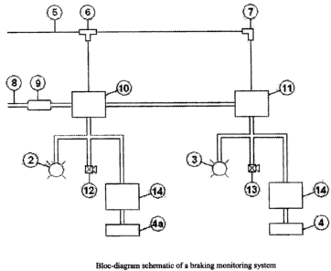
FIG. 1 is a block-diagram of braking monitoring system of the present
invention for air
brakes using two pressure sensors
FIG. 2 is a block-diagram of braking monitoring system for air brakes using
one pressure
sensor.
FIG. 3 shows a perspective view of the assembly of the braking monitoring
system.
FIG. 4 is a block-diagram of braking monitoring system for air brakes provided
with an
electronic control unit.
CA 02477398 2004-08-12
DETAILED DESCRIPTION OF THE PREFERRED EMBODIMENT
Referring now to drawings, Fig. 1 shows a block-diagram of the first
embodiment
of the brake monitoring system according to the present invention comprising
sensor
means including sensor 10 that is a low-pressure switch which is activated
when above
normal pressure is applied to brakes, and sensor 11 which is high-pressure
switch which
is activated when excessive pressure is applied to brakes. Sensors 10 and 11
are
connected to an air hose 5 from the braking system (not shown) by means of T-
fitting
link 6 and 90° link 7, and to an electric wire 8 from vehicle power
supply provided with a
fuse 9 to protect the electrical system from overload or short circuit. Sensor
10 is also
connected to a signal means, such as light indicator 2 and low volume buzzer
12 provided
to signal when pressure is above normal level. Sensor 11 is connected to a
light indicator
3 and a high volume buzzer 13 provided to warn the driver when an excessive
pressure is
applied to brakes. Each of sensors 10 and 11 are provided with a debouncing
circuit 14
and event counters 4 and 4a respectfully.
It must be emphasized that definition of normal, above normal and excessive
pressure can vary from one brake manufacturer to another, and thus cannot be
defined.
The most common parameters are 1-20 psi for normal pressure, 20-30 psi for
above
normal and all pressure above 30 psi is excessive pressure. However, these
parameters
can be set by the end user for their own purposes, and thus the above
parameters are
given as an illustration of possible settings. Other settings will be covered
by the scope of
the invention.
When the driver applies the brakes, air from air brake supply is sent via hose
5 to
sensors 10 and 11 of the brake monitoring system sensor, which evaluate the
pressure
level applied to brakes. If the driver applies above normal pressure level,
sensor 10 is
triggered and latched while the pressure is above normal level. As soon as
sensor 10 is
latched, light indicator 2 and warning buzzer 12 are both turned on. Counter
4a will
monitor the number of times above normal pressure level was applied.
CA 02477398 2004-08-12
6
If more pressure is applied on the truck's braking system, the system goes
into a
condition called 'excessive pressure'. As soon as the system reaches this
condition,
sensor 11 is triggered and latched. At the same time, light indicator 3 and
warning buzzer
13 will be activated. Event counter 4 will monitor the number of time the
excessive
pressure level was applied.
Each counter 4 and 4a are protected against rebounds that can be produced by
sensor's electrical contacts by means of the pressure switch debouncing
circuits 14.
These circuits 14 are provided to prevent counters 4 and 4a from counting more
than one
event. They mask the mechanical rebounds made by switches 10 and 11 to event
counters
4 and 4a. Those circuits are used as protection due to the fact that when
contacts of each
switch are closed, contact never locks instantly and has a period of 20
microseconds or
less before contact locks perfectly. During this short period of time, the
contact will
rebound, passing from "closed" state to "open" state. Industrial event
counters are very
sensitive to these rebounds and react each time.
Fig. 2 is a first modification of the embodiment shown on Fig. 1, except that
sensors 10 and 11 are replaced by one double pole pressure switch 20 having
one pole A
set as a low-pressure switch and the other pole B set as a high-pressure
switch.
Fig. 3 shows an assembly of braking monitoring system including lights 2 and
3,
event counters displays 4 and 4a and enclosure 1.
Fig. 4 shows a second modification of embodiment of Fig. 1 additionally
comprising electronic control unit 15 placed between sensors 10 and 11 and
signal means
or light indicators 2 and 3 and buzzers 12 and 13. Electronic control unit 15
is provided to
monitor and record the information to be downloaded from communication port 16
connected to unit 15. Recorded information may be sent to a remote station by
means of a
satellite output 17 connected to unit 15. Similar to system of Fig. 1, air
pressure in the air
line or hose 5 of brakes will be sent to sensors 10 and 11. Electronic control
unit 15 will
activate light indicators 2 and 3 and buzzers 12 and 13. Event counters 4 and
4a will
CA 02477398 2004-08-12
7
monitor the number of times pressure will go above normal or excessive levels.
It should
be noted that embodiment of Fig. 4 does not have debouncing circuits 14 due to
the
presence of electronic control unit 15.
Thus, it can be seen that the objects of the present invention have been
satisfied
by the structure presented hereinabove. While in accordance with the Patent
Statutes,
only the best mode and preferred embodiments of the present invention have
been
presented and described in detail, it is to be understood that the invention
is not limited
thereto or thereby. Accordingly, for an appreciation of the true scope and
breadth of the
invention, references should be made to the following claims.