Note: Descriptions are shown in the official language in which they were submitted.
CA 02477502 2004-08-25
WO 03/074846 PCT/GB03/00854
Improvements In and Relating to Gas Flow Arrangement
Apparatus and to Apparatus for Removing Pollutants from
Gas Streams
Field of the Invention
The present invention relates to gas flow arrangement
apparatus and to pollutant removal devices, which may
incorporate such gas flow arrangements.
Background to the Invention
Pressure is continuing to grow on vehicle manufacturers to
reduce the amount of pollutants, especially particulates
in gas streams emitted from vehicle exhausts. Attempts
have been made to collect particulates from gas streams
using electro-static precipitation, but generally these
fail because the performance of the apparatus degrades
substantially over time so it cannot be used in a
practical environment.
The present invention finds particular, but not exclusive,
application in the field of the removal of pollutants from
vehicle exhaust gas streams. In this technological
application, often a filter is used to remove pollutants,
especially particulate pollutants. However, as
particulate material is built up in the filter, the
porosity of the filter decreases thus increasing back
pressure on the exhaust system which can reduce engine
3o efficiency. Since environmental concerns are the primary
reason for removing pollutants, such a decrease in
efficiency, with a resultant increase in pollutants,
CONFIRMATION COPY
CA 02477502 2004-08-25
WO 03/074846 PCT/GB03/00854
2
defeats the object of many such proposed filtration
devices.
One particular problem area is in relation to the
particulate material that is agglomerated. For instance,
in a prior art electro-static precipitation apparatus of
this types a central electrode is mounted within a
circular cylindrical solid-walled tube, whereby
particulates are charged by the electrode and attracted to
the solid-walled container. However, once particulates
arrive at the tube wall over time they agglomerate and can
eventually be swept out through the vehicle exhaust by the
continued flow of exhaust gas flow stream over the
agglomerated particulate.
In other prior art devices filters have been proposed to
remove particulates from gas streams. However, in this
case over time particulate build up in the filters reduces
their efficiency and causes back-pressure reducing engine
efficiency also.
It is an aim of preferred embodiments of the present
invention to obviate or overcome at least one disadvantage
of the prior art, whether referred to herein or otherwise.
Summary of the Invention
According to the present invention in a first aspect,
there is provided a gas flow arrangement apparatus
3o comprising a gas entrance and a gas exit, a first flow
path from the gas entrance to the gas exit through a means
for at least partly removing at least one pollutant from a
CA 02477502 2004-08-25
WO 03/074846 PCT/GB03/00854
3
gas flow stream and second flow path from the gas entrance
to the gas exit other than through the removing means.
Suitably, gas passing through the pollutant removing means
intersects the first gas flow.
Thus pressure differences can be minimised and undue back
pressure is avoided. To the extent that gas is blocked
from a first it can follow the second flow path avoiding
the filter.
Suitably, the first flow path diverges from the second
flow path upstream of the pollutant removing means.
Suitably, the first flow path and the second flow path
intersect with each other downstream of the pollutant
removing means. Thus the gas in one flow path is
reintroduced into the gas of the other flow path.
Suitably, the first gas flow splits from the second gas
flow path at a separator for diverting pollutant to the
pollutant removing means. Suitably, the separator is
generally conically shaped with an opening for one of the
gas flow paths therethrough.
Suitably, the first flow path diverges from the second
flow path at a tube through which gas can pass. Suitably,
the tube is a perforated tube.
3o The first and second flow paths may be in common for some
of their respective passages through the arrangement, but
they form discrete flow paths before intersecting
downstream of the filter.
CA 02477502 2004-08-25
WO 03/074846 PCT/GB03/00854
4
Suitably, the arrangement comprises a gas flow tube for
the second flow path, which gas flow tube comprises a slot
for the first gas flow path to join the second gas flow
path.
Suitably, the arrangement comprises a first chamber, a
second chamber and a third chamber, whereby gas enters
into a first chamber, passes into a second chamber at
which the first flow path diverges from the second flow
path, and whereby gas can flow into the third chamber
through two openings one of which comprises the pollutant
removing means, and in which there is an exit for gas from
the third chamber.
Suitably, the pollutant removing means comprises a filter.
Suitably, the filter comprises a regenerative filter.
Suitably, the filter is electrically regenerative.
Thus, the arrangement provides a gas flow apparatus.
According to the present invention in a second aspect,
there is provided a pollutant removal device for at least
partly removing a pollutant from a gas flow, the device
comprising a gas flow arrangement apparatus according to
the first aspect of the invention.
Suitably, the device comprises means for at least
partially ionising gas flow. Suitably, the ionising means
comprises an electrode for electrostatic precipitation.
Suitably, the electrode is mounted in the second chamber.
Suitably, the electrode is mounted in the first chamber.
CA 02477502 2004-08-25
WO 03/074846 PCT/GB03/00854
Suitably, the apparatus comprises a tube through which the
gas stream at least partly flows, whereby the tube is at
least partly porous to the gas stream.
5
Suitably, the tube is at least partly about the ionising
means.
Suitably, the tube is perforated. Suitably, the tube
comprises a plurality of holes therethrough. Suitably,
the holes are evenly spaced. Suitably, the holes are
evenly sized. Suitably, the perforated region of the tube
is substantially annular. Suitably, the perforated region
of the tube extends for a substantial length thereof.
Suitably, the tube comprises at least one slot
therethrough. Suitably, a plurality of slots is provided.
Suitably, the slots are substantially evenly distributed
about the tube. Suitably, the at least one slot runs
longitudinally along the tube.
Suitably, a major portion of the tube is porous.
Alternatively a minor portion of the tube is porous.
Suitably, the tube is circular in cross-section.
Suitably, the tube comprises an inlet and an outlet.
Suitably, the cross-sectional area of the tube decreases
along its length from the input to the output thereof.
Suitably, the tube is at least partly coated with a
barrier coating for slowing the discharge time of charged
agglomerates.
CA 02477502 2004-08-25
WO 03/074846 PCT/GB03/00854
6
Suitably, the electrode is mounted at one end thereof
only.
Suitably, the tube is located in the first and second gas
flow paths. The tube acts to split the gas flows and
concentrate at least one pollutant in one flow path for
subsequent removal.
Suitably, the apparatus comprises a first expansion tube
in fluid communication with an apparatus gas inlet.
Suitably, the diverting tube extends from the first
expansion tube to a second expansion tube defined by the
tube. Suitably, there is a third expansion tube about the
diverting tube into which gas can flow through the
diverting tube. Suitably, a filter is located between (in
respect of gas flow) the second and third expansion tubes.
Suitably, the device is arranged whereby at least one
2o pollutant is biased towards the first flow path (ie a
substantial majority of an input pollutant flows through
the first flow path, subject to being trapped by the
f filter) .
Suitably, a catalytic converter is provided in the second
flow path.
Suitably, the electrode projects from the first chamber in
to the second chamber.
Suitably, the second flow path includes a Catalytic
converter.
CA 02477502 2004-08-25
WO 03/074846 PCT/GB03/00854
7
Suitably, the device is for fitting to a vehicle exhaust.
Suitably, the device is for fitting in place of the_
silencer of a vehicle exhaust.
According to the present invention in the third aspect,
there is provided an apparatus for removing pollutants
from a gas stream, the apparatus comprising means for
charging particulates in the gas stream and a tube through
which the gas stream at least partly flows, whereby the
tube is at least partly porous to the gas stream and the
apparatus additionally comprises means for collecting at
least one pollutant.
Suitably, the tube is at least partly about the charging
means. Suitably, the charging means comprises an
electrode.
Suitably, the tube is perforated. Suitably, the tube
comprises a plurality of holes therethrough. Suitably,
the holes are evenly spaced. Suitably, the holes are
evenly sized. Suitably, the perforated region of the tube
is substantially annular. Suitably, the perforated region
of the tube extends for a substantial length thereof.
Suitably, the tube comprises at least one slot
therethrough. Suitably, a plurality of slots is provided.
Suitably, the slots are substantially evenly distributed
about the tube. Suitably, the at least one slot runs
longitudinally along the tube.
Suitably, a major portion of the tube is porous.
Alternatively a minor portion of the tube is porous.
CA 02477502 2004-08-25
WO 03/074846 PCT/GB03/00854
8
Suitably, the tube is circular in cross-section.
Suitably, the tube comprises an inlet and an outlet.
Suitably, the cross-sectional area of the tube decreases
along its length from the input to the output thereof.
Suitably, the electrode is mounted at one end thereof
only.
Suitably, there is a first gas flow path from an apparatus
gas inlet to an apparatus gas outlet and a second gas flow
path from the apparatus gas inlet to the apparatus gas
outlet. The first and second gas flow paths may be in
common for a part thereof. Suitably, a filter is located
in the second gas flow path. Suitably, the tube is
located in the first and second gas flow paths. The tube
acts to split the gas flows and concentrate at least one
pollutant in one flow path for subsequent removal.
Suitably, the apparatus comprises a first expansion .tube
in fluid communication with an apparatus gas inlet.
Suitably, the diverting tube extends from the first
expansion tube to a second expansion tube defined by the
tube. Suitably, there is a third expansion tube about the
diverting tube into which gas can flow through the
diverting tube. Suitably, a filter is located between {in
respect of gas flow) the second and third expansion tubes.
Suitably, the filter comprises an electrically
regenerative filter.
CA 02477502 2004-08-25
WO 03/074846 PCT/GB03/00854
9
Suitably, the apparatus is for removing pollutants from an
exhaust gas stream, preferably a vehicle exhaust gas
stream.
According to the present invention in a fourth aspect,
there is provided a combustion generator and an apparatus
according to the second or third aspects of the invention
in which exhaust gas from the generator flows to an
apparatus inlet.
to
Suitably, the generator is an internal combustion engine.
Brief Description of the Drawings
The present invention will now be described, by way of
example only, with reference to the drawings that follow;
in which:
Figure 1 is a schematic perspective (partly cut away)
illustration of a gas flow arrangement apparatus according
to an embodiment of the present invention.
Figure 2 is a schematic perspective (partly cut away)
illustration of the gas flow arrangement shown in Figure 1
from a reverse angle.
Figure 3 is a longitudinal cross-sectional view of the
arrangement shown in Figures 1 and 2.
Figure 4 is an enlarged partly cut away and sectional
drawing of the filter shown in Figures 1 and 2.
CA 02477502 2004-08-25
WO 03/074846 PCT/GB03/00854
Figure 5 is a schematic partly cut away illustration. of an
embodiment of a particulate filtration device according to
the present invention.
5 Figures 6 and 7 are schematic partly cut away
illustrations of two further embodiments of a device
according to the present invention.
Figure 8 is a schematic longitudinal cross-sectional view
to of an electrode mount.
Figure 9 is a schematic partly-sectional elevation of a
gas flow arrangement apparatus according to a yet further
embodiment of the present invention.
Figure 10 is a perspective view of a second gas flow path
tube and filter of Figure 9.
Figure 11 is a sectional view of a further electrode
mounting arrangement.
30
Figure 12 is a plan elevation (external walls cut away) of
an apparatus according to a further embodiment of the
present invention.
Figure 13 is a side elevation of Figure 12.
Figure 14 is a perspective illustration of Figures 12 and
13.
Figure 15 is a plan elevation (external walls cut away) of
an apparatus according to a yet further embodiment of the
present invention.
CA 02477502 2004-08-25
WO 03/074846 PCT/GB03/00854
11
Figure 16 is a perspective illustration of Figure 15.
Figure 17 is a plan view of a yet further embodiment of
the present invention.
Figure 18 is a side elevation of Figure 17.
Figure 19 is a sectional, inverted plan view corresponding
to Figure 17.
Description of the Preferred Embodiment
Referring to Figures 1-3 of the drawings that follow,
there is shown a gas flow arrangement apparatus within a
circular cylindrical tubular body indicated by dashed line
2. The body 2 is defined internally by wall plates 4, 6,
8 and 10 respectively into a first chamber 12, a second
chamber 14 and a third chamber 16. The body 2 is provided
with a gas entry tube 18 and gas exit tube 20. Gas entry
tube 18 extends from the exterior wall plate 4 to first
chamber 12. That is, gas enters at the entrance of 18 and
exits into first chamber 12. Gas exit tube 20 extends
from the exterior of wall plate 10 to third chamber 16.
Additionally, there is provided a perforated tube 22
extending between first chamber 12 and third chamber 16,
the perforations opening into second chamber 14. The tube
22 is highly perforated whereby in a given annulus there
is more area taken up by holes than by solid. The
preferred structure is substantially constant radially and
longitudinally.
CA 02477502 2004-08-25
WO 03/074846 PCT/GB03/00854
l2
A filter 24 for removing pollutants from the gas stream is
mounted in third Chamber 16 about an opening 26 between
third chamber 16 and second chamber 14.
The filter 24 is an electrically regenerative filter such
as the filter identified as 3M part number SK-1739.
The filter 24 is. shown in more detail in Figure 4 of the
drawings that follow. The filter 24 comprises a tubular
outer body 28 of a NEXTEL 312 filtration mounted on a
porous metallic frame 30 which is connected to earth
(which may be a floating earth) at one end 32. The other
end 34 provides an electrical connection 36 (see also
Figures 1 and 2) to a power supply 37 (Figure 5) to
achieve heating and regeneration of the filter 24 as is
known in the art.
An electrode 38 is mounted on wall plate 10 by a ceramic
electrode mount 39 to project into the hollow interior of
perforated tube 22 as shown in cross-section in relation
to Figure 4 of the drawings that follow in which
corresponding reference numerals are used.
In use, pollutant eg particulate carrying gas enters the
arrangement at 18 and passes into first chamber 12 from
which its only route is into perforated tube 22. In
operation the electrode is highly charged to between l8kV-
40kV negative polarity d.c. to ionise or charge
particulates in the gas stream forcing them through the
3o perforated holes of the tube 22 in to second chamber 14
(under full load the potential may be about lOkV).
Additionally, it is believed that the gas becomes at least
partly ionised.
CA 02477502 2004-08-25
WO 03/074846 PCT/GB03/00854
13
The perforated tube 22 opens into third chamber 16
allowing gas to pass through exit tube 20 to exhaust.
Further, gas can flow from second chamber 14 to third
chamber 14 through hole 26 through filter 24. Thus filter
24 can collect particulate material. The filter 24 is
regenerative so that at intervals it is electrically
regenerated. This need not be on a regular basis.
However, if for any reason the filter 24 does not
regenerate fully or a heavy loading occurs causing back
pressure between filter 24 and second chamber 14, this is
compensated for because gas can still flow to exit tube 20
through perforated tube 22 and third chamber 16. Thus
build up of particulates (or other pollutants) in filter
24 will not cause undue back pressure on the engine
providing an exhaust stream to the gas flow arrangement.
As a result, the problem of back pressure encountered in
relation to prior art filtration arrangements is overcome
by embodiments of the present invention and there is
provided a geometrically efficient and compact gas flow
arrangement.
Thus embodiments of the present invention provide a first
gas flow path 40 (Figure 5) from gas entrance 18 to gas
exit 20 via first chamber 12, tube 22, third chamber 16
through filter 24 and second chamber 14 and a second gas
flow path 42 (Figure 4) from gas entrance 18 to gas exit
20 via first chamber 12, tube 22 and second chamber 14
which is other than through the filter 24.
Referring to Figure 6 of the drawings that follow, there
is shown another embodiment of a gas flow arrangement and
pollutant removal device according to the present
CA 02477502 2004-08-25
WO 03/074846 PCT/GB03/00854
14
invention. The arrangement and device is similar to that
described in relation to Figure 5 (and similar reference
numerals are used for corresponding integers), except that
the first gas flow path 40 through filter 24 is generally
straight on, ie the flow path does not diverge
substantially from the path of the tube 22 to the filter
24 and the second gas flow path 42 follows the more
tortuous route as shown.
To bias the particulate pollutants to follow first gas
flow path 40 at Figure 6, instead of a highly perforated
tube 22 (considered over the length at tube 22) a small
area 50 of perforated tube 52 with a lower hole density is
provided. The less perforated tube 52 is not annular, it
just occupies a slot in the tube. As the effect of the
corona discharge electrode 38 with the floating earth of
the tube 52 is to draw particulates to the side (tube 52)
walls where they tend to agglomerate, by providing less
open area for the agglomerated particulate to pass
through, it' is less likely that particulates will follow
the second flow path 42.
Another difference in the Figure 6 embodiment is the
provision of a catalytic converter 54 in the second flow
path 42 for the removal of hydrocarbons from the gas
stream.
Figure 7 is a yet further embodiment of the present
invention substantially similar to the embodiment of
Figure 6, except that four equally spaced longitudinal
slits 60 are provided over a substantial minority of the
surface area of tube 62.
CA 02477502 2004-08-25
WO 03/074846 PCT/GB03/00854
Referring to Figure 8 of the drawings that follow, the
electrode mount 39 is shown in more detail. The electrode
mount 39 is a one piece ceramic construction having a
longitudinal hole 64 therethrough for the electrode 38
5 (not shown in Figure 8). The electrode projects from
distal end 66 and is connected to a power source at end
68. The electrode mount 39 is held by a bracket (not
shown.) about shoulder 70. Protrusions 72a, 72b and 72c
project from the exterior of electrode mount 39. The
10 protrusions 72 are partly hollow, rebated conical shapes
that provide a tortuous route from the electrode 38
projecting from distal end 66 to earth to reduce leakage.
Referring to Figures 9 and 10 of the drawings that follow,
15 there is shown a gas flow arrangement apparatus 80 for use
in a pollutant removal device in which outer walls are not
shown for clarity. The apparatus 80 comprises an ionising
electrode 82 in an electrode mount 83, partly surrounded
by an electrode hood 84. Electrode 82 extends into an
electrode tube 86 which terminates in an outwardly
diverging end 88. Spaced from electrode tube 86 is a
second gas flow path tube 90 having a generally sonically
shaped entrance 92 with a central opening 94. The opening
94 is substantially inside the diameter of the walls of
electrode tube 84. Tube 90 terminates in an exit 98.
About tube 90 is a catalytic filter 100 for at least
partly removing pollutants from a gas stream passing
therethrough.
Operation of the embodiment of Figures 9 and 10 is similar
to that of the embodiments described above. Exhaust
gases, carrying pollutants, enter the apparatus 90
upstream of electrode 82, and pass over hood 84 which
CA 02477502 2004-08-25
WO 03/074846 PCT/GB03/00854
16
serves to help prevent pollutant build up on electrode 82.
The electrode 82 is charged to ionise pollutants. in the
gas flow, which pollutants are therefore attracted to the
walls of electrode tube 86 as they flow downstream,
leaving relatively cleaner gas towards the centre of the
flowstream. The conical opening of second gas flow path
tube 90 serves to help deflect pollutant into a first gas
flow path (indicated schematically by arrows labelled 102,
while the second gas flow path is indicated by arrows
labelled 104). The first gas flow path 102 passes through
filter 100, which removes some pollutants, and rejoins
second gas flow path 104 through a slot 96 in tube 172
downstream to the filter 100. The slot 96 is relatively
small compared to the surface area of tube 90. The
pressure difference either side of slot 96 is believed to
encourage now relatively cleaner gas from the first gas
flow path downstream of filter 100 to rejoin the second
gas flow. path. Second gas flow path 104 passes through
second gas flow path tube 90 carrying relatively cleaner
gas. The rejoined gas streams, pass out of the apparatus
at exit 98.
In any of the embodiments a resistive organic barrier
coating may be provided over the inner surface of the tube
(22 in Figure 1) downstream of the beginning of the
electrode. The barrier coating is preferably over
substantially all of the inner surface of the tube. The
coating is TLHB/02 available from Camcoat Performance
Coatings on 127 Hoyle Street, Bewsey Industrial Estate,
Warrington, WA5 5LR, United Kingdom. It is believed that
by reducing the discharge rate of the agglomerated
particulates along the tube by providing the coating, the
CA 02477502 2004-08-25
WO 03/074846 PCT/GB03/00854
17
particulates are more likely to stay in the vicinity of
the tube.
Referring to Figure 11 of the drawings that follow, an
alternative electrode mounting arrangement is shown. Both
the electrode mount 83 and electrode hood 84 are formed
from a ceramic high purity alumina material, sold under
the trade mark SINTOX FF which is believed to have a
dielectric strength of between 30 and 40 kV/mm.
The electrode mount 83 comprises a first ceramic mounting
portion 88 and a second ceramic mounting portion 90
mounted in bore 86. The second ceramic mounting portion
90 is of a reduced external diameter compared with the
first ceramic mounting portion. The electrode mount 83
can be formed from a single ceramic. Thus the electrode
mount 83 has a portion of a first diameter and a portion
of a lesser diameter towards the distal end (from which
the electrode projects) thereof. The second portion 90 of
second diameter extends a substantial distance beyond hood
84 typically at least 30mm.
The hood 84 protects a substantial part of the electrode
(mounted in central bore 86) from the inflow of pollutants
containing gas thus minimising the risk of shorting.
However, it is believed that at least a 30mm length of the
electrode needs to project beyond the hood. It is noted
that the gas inlet is not around the electrode but rather
alongside it and can be protected from it by the hood 84.
The electrode mount and hood can be glazed to reduce
pitting of the surface and hence the build up of
CA 02477502 2004-08-25
WO 03/074846 PCT/GB03/00854
18
particulates thereon. The glaze acts as a means for
smoothing the surface of the electrode mount.
It is noted that although the maximum exterior diameter of
each generally sonically shaped protrusion 83 decreases in
a downstream direction, the minimum internal diameter are
substantially the same ~10%. This is believed to provide
additional burn-off points if required.
1o The alumina Content of hood and mount is typically at
least 80%, normally at least 90%, preferably more than
95%, more preferably more than 97% and most preferably
more than 99%.
Referring to Figure 12-14 of the drawings that follow,
there is shown a further embodiment of a gas flow
arrangement and apparatus for removing pollutants
according to the present invention. In the Figure 12-14
embodiment, exhaust gas enters through an inlet 100 into a
2o perforated baffle tube 102 from which all of the entering
exhaust gases flow into first chamber 104. In chamber
104, electrode mount 106 over a substantial part of which
lies hood 108 mounts an electrode 110 which projects into
a second chamber 112 defined by field tube 114. Field
tube 114 includes an opening in its end to an intermediate
chamber 116, the only exit from which is into filter 118.
An alternative flow path is provided via an opening 120 in
the wall of field tube 114. The opening 120 is provided
with an upstanding lip 122 projecting inwardly into the
field tube 114 at at least the upstream portion thereof,
but in this embodiment along the full length thereof.
Further, the opening 120 comprises a generally V-shaped
upstanding leading edge 124 at an upstream end thereof.
CA 02477502 2004-08-25
WO 03/074846 PCT/GB03/00854
19
Fluid flow path leads from field tube 114 via opening 120
leads to a perforated exit tube 126. Perforations 128 in
exit tube 126 permit gas passing through filter 118 to re-
enter the diverted gas flow leading to exit 130.
It is noted that the leading edge 132 of field tube 114
comprises a returned edge that is curved back on itself
whereby the exterior edge of the leading edge 132 of field
tube 114 is configured relative to the electrode whereby
something else lies between it and electrode and/or
electrode mount. In this case, another part of the field
tube lies between the external edge and both of the
electrode mount 106 and electrode 110.
Upstanding lip 122 and leading edge 124 help to divert
particulates away from opening 120 from which it is
intended that cleaner gas flows. Together, upstanding lip
122 and leading edge 124 act as means for diverting
particulates away from the opening 120.
The electrode, electrode mount and hood are not shown in
Figure 15.
Referring to Figures 15 and 16 of the drawings that
follow, there is shown a further gas flow arrangement
apparatus and apparatus for removing pollutants according
to the present invention.
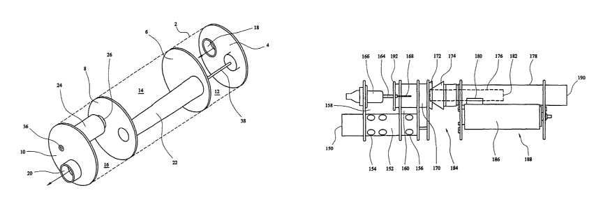
In Figures 15 and 16, the apparatus comprises an inlet 150
into which exhaust gas flows into a baffle chamber 152
having first exit ports 154 and second exit ports 156.
First exit ports 154 exit to first clamber 158. Second
exit ports 156 exit into an intermediate chamber 160
CA 02477502 2004-08-25
WO 03/074846 PCT/GB03/00854
having holes 162 permitting the flow of gas back into
first chamber 158. An electrode mount 164 (Figure 15
only), covered for a substantial part thereof by hood 166
(Figure 15 only), is provided in first chamber 158 for
5 mounting of an electrode 168 (Figure 15 only) within a
field tube 170. At its downstream end, field tube 170
terminates in an outwardly diverging portion 172 adjacent
a generally conical portion 174 within which is a tube 176
extending to an exit tube 178.
In exit tube 178 is provided an opening 180 prior to the
exit 182 of tube 176.
In use, exhaust gas flows in via inlet 150 into field tube
170 via first chamber 158. Particulates in the field tube
are charged by electrode 168 and tend towards the walls of
field tube 170. Thus the particulates are diverted from
the central flow of gas through field tube 170. The
central flow of gas enters tube 176 into exit tube 178.
2o Other gas bearing a higher loading of particulates exits
towards the periphery of field tube 170 and therefore
tends not to enter tube 176. The generally conical
portion 174 acts as a deflector for the particulates
encouraging them not to enter tube 176. The particulate
laden gas exiting field tube 170 other than through tube
176 enters a second intermediate chamber 184 leading to
filter 186. Gas exiting filter 186 can only exit the
apparatus via opening 180 and into exit tube 178. However
the gas exiting filter 186 tends to be at a low velocity
compared to the high velocity gas exiting tube 176. The
pressure differential causes the gas in third chamber 188
about filter 186 to be drawn through opening 180 into exit
tube 178 and hence to outlet 190.
CA 02477502 2004-08-25
WO 03/074846 PCT/GB03/00854
21
Field tube 170 may include a curved leading edge 192 as
described above in relation to figures 12-14.
Figures 17 and 18 show a further embodiment of the present
invention. In Figures 17 and 18, for clarity the
electrode mount and electrode are not shown.
Referring to Figures 17 and 18, there is shown a gas inlet
into a perforated expansion chamber 202, from which all
the input gas flows into a first chamber 204 and from
there into field tube 206 which leads to filter 208.
Alternatively, through opening 210 in field tube 206 gas
can flow to exit tube 212 in which there is a
concentrically mounted flow tube 214 and in an exterior
wall of which an opening 216 mounted behind (relative to
the gas flow) the exit 218 of tube 214. In exit tube 212
a catalytic body 220, acting as a catalytic converter,
optionally can be mounted. In use, gas enters through
inlet 200, passes through expansion tube 202 into first
chamber 204 and then into field tube 206 in which
particulates in the gas flow are charged. Charged
particulates tend towards the side wall of field tube 206
and an upstanding lip may be provided around 210 to divert
particulates therefrom. Particulates proceeding from
field tube 206 to filter 208 are filtered and the gas flow
can continue towards exit 222 via holes 216 into exit 212.
Although the first and second gas flow streams are shown
separately in the same tube or area of the apparatus, this
is for explanatory purposes only and it will be
appreciated that in these regions the gas flows are
intermingled.
CA 02477502 2004-08-25
WO 03/074846 PCT/GB03/00854
22
It is noted that there may be a plurality of devices, a
plurality of filters and/or a plurality of catalytic
converters.
Instead of using standard direct current as described
above, high frequency superimposed a.c can be used.
The reduced gas flow through the filter when compared with
a corresponding device in which all of the input gas
stream flows through the filter makes the electrical
regeneration of the filter more efficient because the
thermal effect of the gas flow is correspondingly reduced.
Preferred embodiments of the present invention find
particular benefit in the application of pollutant,
especially particulate removal from exhaust gas streams,
especially of internal combustion engines. For such
engines the arrangement can be mounted in place of the
vehicle silencer to avoid taking up unnecessary space.
The device may be upstream or downstream of a catalytic
converter.
The reader's attention is directed to all papers and
documents which are filed concurrently with or previous to
this specification in connection with this application and
which are open to public inspection with this
specification, and the contents of all such papers and
documents are incorporated herein by reference.
All of the features disclosed in this specification
(including any accompanying claims, abstract and
drawings), and/or all of the steps of any method or
CA 02477502 2004-08-25
WO 03/074846 PCT/GB03/00854
23
process so disclosed, may be combined in any combination,
except combinations where at least some of such features
and/or steps are mutually exclusive.
Each feature disclosed in this specification (including
any accompanying claims, abstract and drawings), may be
replaced by alternative features serving the same,
equivalent or similar purpose, unless expressly stated
otherwise. Thus, unless expressly stated otherwise, each
feature disclosed is one example only of a generic series
of equivalent or similar features.
The invention is not restricted to the details of the
foregoing embodiment(s). The invention extend to any novel
one, or any novel combination, of the features disclosed
in this specification (including any accompanying claims,
abstract and drawings), or to any novel one, or any novel
combination, of the steps of any method or process so
disclosed.