Note: Descriptions are shown in the official language in which they were submitted.
CA 02478136 2011-09-30
69897-74
DETERMINING THE PRESSURE OF FORMATION FLUID
IN EARTH FORMATIONS SURROUNDING A BOREHOLE
Field of the Invention
[0002] The present invention relates generally to the field of oil and gas
exploration. More
particularly, the invention relates to methods for determining at least one
property of an earth
formation surrounding a borehole using a formation tester.
Background of the Invention
[0003] The term "wireline formation tester" is the generic name in the
petroleum industry
for a wireline logging tool used for determining formation fluid pressure and
other
parameters in a reservoir. A prior art wireline formation tester typically
includes a formation
pressure tester tool having a probe with a pretest chamber and a hydraulically-
driven pretest
piston. A pressure sensor is coupled to measure tool pressure.
[0004] Measurement of formation fluid pressure by a formation tester may be
repeated
once or twice without changing the position of the probe. Proper placement of
the formation
tester requires lowering the formation tester into the well and pressing the
probe of the
pressure tester tool against the borehole wall. The measurement procedure
includes a
"draw-down" procedure followed by a "build-up" procedure.
[0005] Before drawdown, the probe is pressed against the mud cake on the
borehole wall.
During drawdown, a small amount of formation fluid (typically 10 cc) is
extracted from the
reservoir. The prior art draw-down procedure includes establishing hydraulic
communication
between tool fluid and formation fluid (by retracting the pretest piston in
the pretest chamber
to reduce the tool pressure and break the mud cake seal), verifying good
hydraulic
communication between tool fluid and formation fluid using the pressure
sensor, and
1
CA 02478136 2011-09-30
69897-74
verifying good hydraulic isolation between tool fluid and borehole fluid using
the pressure
sensor.
[0006] Immediately following drawdown, the pretest piston is stationary in the
retracted
position and fluid in the pretest chamber is at a pressure below the pressure
of formation
fluid.
[0007] Build-up includes allowing a build-up period to establish pressure
equilibrium
between tool fluid and formation fluid. During build-up, the pretest piston
remains stationary
in the retracted position. Formation fluid flows from the formation into the
tool because
formation fluid pressure is higher than tool pressure. Continued inflow allows
tool pressure
to build up until equilibrium is established. When equilibrium is established,
tool pressure
equals reservoir pressure. The changing pressure in the tool is monitored by
the pressure
sensor. The build-up procedure includes waiting for equilibrium to be
established; and
setting pressure of formation fluid equal to the measured tool pressure.
[0008] When using wireline formation testers for determining formation fluid
pressure,
especially in low permeability formations, it is most desirable that
equilibrium be established
within a short time. If the formation tester is set at a particular location
for too long a time, it
could stick in the borehole and become difficult to remove. Fear of the tool
sticking in the
borehole is a major concern and is frequently cited as the main reason for not
using wireline
formation testers more often. For this reason, the tester is usually allowed
to remain on the
borehole wall for no more than a limited period of time. The limited period of
time varies
widely depending on the nature of the formation and the downhole borehole
pressure,
temperature, etc. Because wireline formation testers often fail to reach
equilibrium within
the time allowed, several data processing extrapolation techniques have been
developed for
estimating reservoir pressure from a time-series of pressure measurements.
These
techniques, to the extent they provide accurate estimates, avoid the need to
wait for
equilibrium to be established. However, these techniques are not generally
viewed as reliable
predictors of actual formation fluid pressure.
2
CA 02478136 2011-09-30
69897-74
Summary of the Invention
According to an aspect of the present invention, there is provided a
method for determining formation fluid pressure in earth formation surrounding
a
borehole, the borehole defining a borehole wall, the borehole wall covered
with mud
cake forming a mud cake seal, the method comprising: providing a tool defining
a
probe and a variable-volume pretest cavity fluid-coupled to the probe;
pressing the
probe into contact with the mud cake; expanding the volume of the cavity to
draw
fluid from the formation in sufficient amount to produce a break in the mud
cake seal
during a draw-down period; detecting an occurrence of a break in the mud cake
seal
by detecting an abrupt change in cavity pressure; holding constant the volume
of the
cavity immediately after detecting the occurrence of the break in the mud cake
seal,
for a sufficient build-up period to establish pressure equilibrium between
cavity fluid
and formation fluid; measuring pressure in the cavity; setting formation fluid
pressure
equal to measured pressure; and minimizing the volume of fluid drawn, thereby
preventing excessive overshoot; such that formation pressure is determined
more
quickly and the risk of the tool sticking in the borehole is reduced.
According to another aspect of the present invention, there is provided
a tool for determining formation fluid pressure in earth formation surrounding
a
borehole, the borehole defining a borehole wall, the borehole wall covered
with mud
cake forming a mud cake seal, the tool comprising: an elongated body adapted
for
downhole operation; a probe, extendable from the elongated body, the probe
defining
an inflow aperture and a low-volume flow line; a pretest piston pump defining
a
variable-volume pretest cavity coupled to the inflow aperture via the low-
volume flow
line; a) means for expanding the volume of the pretest cavity in sufficient
amount to
produce a break in the mud cake seal, b) means for detecting an occurrence of
a
break in the mud cake seal, c) means for holding constant the volume of the
cavity
immediately after detecting the occurrence of the break in the mud cake seal,
for a
sufficient build-up period to establish pressure equilibrium between pretest
cavity fluid
and formation fluid; and d) means for minimizing the volume of fluid drawn,
thereby
2a
CA 02478136 2011-09-30
69897-74
preventing excesive overshoot, such that formation pressure is determined more
quickly and the risk of the tool sticking in the borehole is reduced, and a
pressure
sensor coupled to measure pressure in the pretest cavity.
[0009] Some embodiments of the invention provide a method and apparatus
for determining formation fluid pressure in earth formation surrounding a
borehole,
using a downhole probe coupled to a pretest piston pump, the pump having a
pretest
chamber and a pretest piston, the chamber and piston defining a variable-
volume
pretest cavity.
2b
CA 02478136 2004-08-17
[00101 In operation, the method requires pressing the probe into contact with
formation at
the borehole wall. The preferred embodiment includes expanding the volume of
the cavity
during a first period of time to establish fluid communication between tool
fluid and
formation fluid by breaking a mud cake seal. Pressure equilibrium is
established during a
second period of time by allowing formation fluid to flow into the tool. When
pressure
equilibrium is established, formation fluid pressure is set equal to tool
pressure.
[00111 Expanding the volume of the cavity during a first period of time to
establish fluid
communication includes expanding the volume of the cavity to draw only the
necessary
volume of formation fluid into the tool to establish and validate fluid
communication, thereby
minimizing pressure overshoot.
100121 A preferred embodiment of the method for determining formation fluid
pressure
in earth formation surrounding a borehole, the borehole defining a borehole
wall, includes
pressing a probe into contact with mud cake and formation at the borehole
wall; expanding a
variable-volume cavity in fluid communication with the probe during a draw-
down period to
break a mud cake seal at the probe; terminating expanding the volume of the
cavity on
detecting a break in the mud cake seal; allowing fluid flow during a build-up
period to
establish pressure equilibrium between tool fluid and formation fluid;
measuring tool
pressure; and setting formation fluid pressure equal to tool pressure.
[00131 Expanding the volume of the cavity includes expanding the volume of the
cavity
during the draw-down period at a selected constant rate in the range of 3-
160cc/minute. A
preferred rate is 5cc/minute.
[00141 Preferably, detecting a break in the mud cake seal includes measuring
tool
pressure and detecting an abrupt change in tool pressure, and detecting an
abrupt change in
tool pressure includes using a finite moving average (FMA) algorithm on the
measured tool
pressure and its first and second time derivatives.
100151 Alternatively, using a formation pressure tester tool in fluid
communication with
a formation, detecting a break in the mud cake seal includes detecting a
difference between a
measured tool pressure and a corresponding tool pressure from a reference tool
pressure
profile, wherein the reference tool pressure profile is measured in a previous
drawdown with
the tool isolated from the formation.
(00161 The invention further provides a formation pressure tester tool for
determining
formation fluid pressure in earth formation surrounding a borehole. The
preferred
CA 02478136 2004-08-17
embodiment includes an elongated body adapted for downhole operation, and a
probe,
extending from the elongated body, adapted to accept formation fluid from the
borehole wall.
A pretest piston pump, the pump having a pretest chamber and a pretest piston,
the chamber
and piston defining a variable-volume pretest cavity moveable pretest piston,
defines a
variable-volume cavity. The variable-volume cavity is fluid-coupled to the
probe via a
flexible conduit. Pressure measuring means is fluid-coupled to the variable-
volume cavity
for measuring tool pressure. Control means for controlling expanding the
variable-volume
cavity and terminating expanding the volume of the cavity on detecting a break
in the mud
cake seal is electrically coupled to the piston pump.
[0017] The formation pressure tester tool preferably includes an elongated
body adapted
for downhole operation; a probe, extendable from the elongated body, the probe
defining a
formation fluid inflow aperture; an electromechanical assembly defining a
variable-volume
cavity; a pretest flow line coupling the formation fluid inflow aperture to
the cavity; pressure
measuring means, pressure-coupled to the cavity for measuring tool pressure;
and control
means for actively controlling the rate of change of volume of the cavity.
[0018] Preferably, the tool includes an electromechanical assembly with a
pretest
chamber and an electrically driven pretest piston; a control means with an
electric motor, a
gearbox, and an electromechanically driven roller screw planetary system; a
dedicated probe;
a flexible conduit; downhole programmable control electronics; and a constant-
volume flow
line has a volume in the range 20 - 30cc.
Brief Description of the Drawings
[0019] FIG. I is a flowchart of a first preferred embodiment of the method of
the
invention, wherein the variable-volume cavity is expanded at a predetermined
constant rate
during drawdown, and expansion is terminated on detecting a break in mud cake
seal.
[0020] FIG. 2 is a schematic illustration of the formation fluid pressure
measurement
tool of a first preferred embodiment located in a wireline tool.
[0021] FIG. 3 is a schematic illustration of the measurement tool of FIG. 2
showing the
main components. of the first preferred embodiment.
[0022] FIG. 4 is a schematic illustration. of the measurement tool of FIG. 2,
showing
detail of the electromechanical assembly.
4
CA 02478136 2011-09-30
69897-74
[0023] FIG. 5 is a graph illustrating the rate of change of cavity volume and
the resulting
rate of change of tool pressure of a first preferred embodiment of the method
of the invention.
[0024] FIG. 6 is a graph illustrating the rate of change of cavity volume and
the resulting
rate of change of tool pressure of a second preferred embodiment of the method
of the
invention.
[0025] FIG. 7 is a schematic illustration of a first alternative to the
measurement tool of
FIG. 2, showing a prior art probe, the tool tapped into the sample conduit.
[0026] FIG. 8 is a schematic illustration of a second alternative to the
measurement tool
of FIG. 2, showing a probe of the type used in a prior art sampling system but
not shared with
a sampling system.
Detailed Description
General
[0027] Embodiments of the invention provide a method and tool for determining
the pressure
of formation fluid in earth formation surrounding a borehole more quickly and
potentially more
accurately than methods used in existing wireline formation testers. By
determining the pressure
more quickly, embodiments of the invention reduce the risk of the tool
sticking in the borehole.
[0028] In particular, the method in a preferred embodiment includes actively
terminating
the expansion of the volume of the cavity of a pretest chamber during the
"draw-down"
period of a method similar to the prior art method described above.
[0029] Actively terminating the expansion of the volume of the cavity upon
detection of
an abrupt change in pressure prevents excessive pressure overshoot. See
"overshoot" in
FIGS. 5 and 6. "Pressure overshoot" refers to the tool pressure always being
less than the
formation pressure Pf at the conclusion of drawdown. Withdrawing fluid from
the formation
into the tool requires that the tool pressure be less than the formation
pressure. Minimizing
overshoot requires that overshoot be no more than required to break the mud
cake seal, and to
create hydraulic communication. Minimizing pressure overshoot also minimizes
the volume
of fluid withdrawn from the formation.
[0030] Minimizing overshoot creates the benefit of minimizing the time it
takes the
pressure in the formation pressure tester tool (herein below referred to as
the "tool pressure")
to equilibrate to the formation fluid pressure (herein below referred to as
the "formation
pressure"). Preferably, a low-volume flow line is used.
CA 02478136 2011-09-30
69897-74
[0031] Minimizing the volume of fluid withdrawn from the formation, and using
a
low-volume flow line are also believed to provide a more accurate measurement
of formation
pressure.
Embodiments of the Apparatus
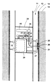
100321 FIG. 2 shows formation pressure tester tool 20 according to an
embodiment of
the invention located within wireline tester 10. The wireline tester is shown
located in
borehole 12, suspended from logging cable 17, and coupled electrically to
surface system 18
via electrical wires in the logging cable.
[0033] FIG. 2 shows probe 21 protruding from elongated body I I and in
physical
contact with formation 15 at one side of the borehole. With probe 21 in
physical contact with
the borehole wall, formation pressure tester too] is 20 is held stationary in
the borehole by
two distal hydraulic anchoring pistons 22 exerting counter-force against the
opposite side of
the borehole. Pressure sensor 36 is coupled to measure pressure in the
variable-volume
cavity of pretest chamber 30. Downhole programmable control electronics 45
controls the
sequencing and timing of the steps of the method by timing measurements from
pressure
sensor 36 and by controlling pretest piston pump 23. The pretest piston pump
operates to
control the volume of a variable-volume cavity (item 33 in FIG. 3). In the
preferred
embodiment the sampling rate for pressure measurements may be set as high as
120Hz.
[0034] FIG. 3 shows probe 21 pressed against mud cake 14 by hydraulic
anchoring
pistons 22, extending from probe driver 29. Electronics 45 controls pistons 22
via probe
driver 29. Downhole programmable control electronics 45 also controls the
pushing of
frame 47. Hydraulic communication between the formation tester and the
formation is
achieved by breaking the mud cake seal at the inflow aperture 26 of probe 21.
Resilient
packer 25 isolates the fluid inside the formation tester from borehole
pressure. Aperture 26 is
coupled to variable-volume cavity 33 via flexible conduit 27 (of pretest flow
line 32) and
rigid conduit 28. Flexible conduit 27 accommodates the advancing and
retracting motion of
probe 21 in the direction of the double arrow in FIG. 3.
[0035] In the first preferred embodiment, the volume of the pretest flow line
is in the
range 20 - 120cc.
[0036] Pretest piston 31 is used to vary the tool pressure P,. Pressure
P,exists in
probe 21, in conduits 27 and 28, and in cavity 33 as measured by pressure
sensor 36. It can
be seen from FIG. 3 that the pressure measured by pressure sensor 36, and the
pressure in
6
CA 02478136 2004-08-17
'cavity 33, are both equal to the pressure at the probe because they are both
in good fluid
communication via conduits 27 and 28.
[0037] FIG. 4 shows detail of electromechanical assembly 60, including pretest
piston
pump 23 and its variable-volume cavity 33. FIG. 4 also shows pretest piston 31
and its
associated piston drive train. The piston drive train includes electric motor
61 and precision
transmission system 62. Transmission system 62 includes reducer 63, shaft 64,
coupling 65,
bearings 66 with ball races 68, and roller screw planetary system 67. Assembly
60 is
electromechanical (in contrast to hydraulic assemblies performing a similar
function in the
prior art) for precision control of the amount of formation fluid drawn into
the pretest
chamber.
[00381 FIG. 4 also shows detail of pretest piston pump 23. Piston pump 23
includes
cylindrical pretest chamber 30 and pretest piston 31. Pretest chamber 30 and
pretest piston
31 together define variable-volume cavity 33. The swept volume of variable-
volume cavity
33 of the preferred embodiment is the swept volume of pretest chamber 30. FIG
4. shows
chamber 30 having a diameter "d" of 30mm and piston 31 having a maximum stroke
"s" of
70mm. As shown in FIG. 4, piston 31 fully retracted defines a maximum cavity
volume V;.
Piston 31 fully extended defines a minimum cavity volume Piston 31 at buildup
position 69 defines variable-volume cavity 33 having a buildup cavity volume
equal to V,,,.
(See FIGS. 4 and 5).
[00391 FIG. 4 also shows detail of precision transmission system 62. FIG. 4
shows that
transmission system 62 includes reducer 63 and roller screw planetary system
67. In a
preferred embodiment reducer 63 is a conventional gearbox reducer that
provides a 75:1
reduction of speed. The roller screw planetary system 67 that drives pretest
piston 31
provides an additional reduction of speed. This electromechanical drive system
provides
precision "push and pull" capability. Output shaft 64 of the gearbox is
coupled via coupling
65 and bearings 66 to roller screw planetary system 67. In the preferred
embodiment of the
formation pressure tester too], the pretest chamber, the pretest piston, and
the
electromechanical assembly provide a selectable drawdown rate covering the
range of 3-
160cc/minute.
[0040] The use of downhole programmable control electronics to control
sequencing and
timing in the present invention avoids the sampling rate limitations incurred
when using
surface electronics. The use of surface electronics imposes severe sampling
rate limitations
because of the inherently narrow bandwidth of the logging cable.
7
CA 02478136 2004-08-17
[0041] The use of flexible conduit, rather than the more elaborate structure
of the typical
prior art probe, serves to avoid volume changes during probe-setting.
[0042] The pretest flow line has a volume in the range 20-120cc. Under benign
conditions, the lower end of this range is preferable.
[0043] The combination of dedicated probe and flexible conduit makes a
constant-volume flow line. A constant-volume flow line is beneficial because
it eliminates a
significant source of disturbance caused by tool movement during pretest.
Alternative Embodiments
[0044] For applications in which a lower pretest flow line volume is
beneficial, the
lower volume is provided by locating probe 21 between pressure sensor 36 and
variable-
volume cavity 33.
[0045] First and second alternative embodiments are shown in FIGS. 7 and 8
respectively. FIG. 7 is a schematic illustration of a first alternative
embodiment, tool 20a,
using prior art probe 81 having formation fluid inflow aperture 82. Tool 20a
is tapped into
pretest flow line 83 that leads to isolation valve 84 and sample riser 85.
[0046] FIG. 8 is a schematic illustration of a second alternative embodiment
tool 20b,
using probe 81 of the type used in a prior art sampling system but not shared
with a sampling
system. Isolation valve 86 is used to isolate tool pressure from external
pressures in the
making of the stored pressure profile of the method illustrated in FIG. 6.
[0047] Although originally configured for wireline application, the formation
pressure
tester tool of the invention may also be incorporated into a logging while
drilling (LWD)
tool.
The Method, Draw-down Phase
[0048] In the preferred embodiment, drawdown is accomplished by actively
expanding
cavity volume VV to establish fluid communication between tool fluid and
formation fluid. In
the preferred embodiment, the volume of the cavity is expanded at a controlled
predetermined constant rate. Alternatively, a control algorithm may be used
based on the
first time-derivative of tool pressure.
[0049] FIG. 5 illustrates the rate of change of cavity volume and the
resulting rate of
change of tool pressure P, of a first preferred embodiment of the method of
the invention. Pfis
the formation pressure. P.;,, is the minimum tool pressure during drawdown. P,
is the
8
CA 02478136 2004-08-17
borehole pressure. Vu, is the maximum cavity volume, corresponding to a
maximum volume
drawdown. V;,, is a minimum cavity volume corresponding to a zero volume
drawdown.
The location of V in FIG. 4 indicates a typical cavity volume when drawdown is
curtailed
upon detection of an abrupt change in tool pressure P,, indicating a break in
the mud cake
seal.
[0050] A first preferred embodiment of the method for detecting a break in the
mud cake
seal includes detecting an abrupt change in tool pressure P,.
[0051] With reference to FIG. 5, as cavity volume V. expands, the increases in
V and the
decreases in P, occur smoothly until the mud cake begins to detach from the
borehole wall.
When this happens, hydraulic communication has been established with the
reservoir. This
event is marked by an abrupt change in the character of P. Drawdown is
terminated as soon
as this change in character of P, occurs. The abrupt change may be detected by
any one of a
number of known mathematical methods of detecting an abrupt change. In a
preferred
embodiment, drawdown is terminated on detection of an abrupt change in the
value P,, or in
the value of one its first or second time derivatives using a finite moving
average (FMA)
algorithm. This algorithm is discussed in "Detection of Abrupt Changes: Theory
and
Application", Michele Bassevilee and Igor Nikiforov, a book, available from P
T R Prentice
Hall, Englewood Cliffs, NJ 07631. The FMA algorithm is discussed under 2.1.3
"Finite
Moving Average Control Charts" on page 38.
[0052] In contrast, a typical prior art drawdown involves expanding the
enclosed volume
at a constant rate (specified by the operator) and in amount usually between 5
cc to 20 cc.
This practice always reduces P, significantly below P. thus necessitating a
time-consuming
build-up phase.
[0053] A second preferred embodiment, illustrated in FIG. 6, of the method for
detecting
a break in the mud cake seal includes detecting a divergence (at cavity volume
V,, in FIG. 6)
between a measured tool pressure and a corresponding tool pressure from a
reference tool
pressure profile. In this embodiment the reference tool pressure profile is
derived from
measurements in a previous drawdown with the tool isolated from the formation.
9