Note: Descriptions are shown in the official language in which they were submitted.
CA 02478196 2004-08-19
-~l
.a.
F. Hoffinann La Roche AG RD5159CA IB/SDL/mo
August 6, 2004
Positioning device for a test element
The present invention relates to a positioning device for a test element and
to a
method for positioning a test element in an analysis apparatus.
1 o For analysis of samples, for 'example of body fluids such as blood or
urine, test
element analysis systems are often used in which the samples to be analyzed
are
located on a test element and, if appropriate, react with one or more reagents
on the
test element before they are analyzed. Optical evaluation, in particular
photometric
evaluation, of test elements is one of the most common methods for rapid
2 5 determination of the concentration of analytes in samples. Photometric
evaluations
are generally used in the field of analysis, environmental analysis and, above
all, in
the area of medical diagnostics. Test elements which are evaluated by
photometry
have great importance in particular in the area of blood glucose diagnosis
from
capillary blood.
'There are various forms of test elements. The main examples are square
panels,
also referred to as slides, at whose centre a multi-layer test field is
situated.
Diagnostic test elements of strip-shaped configuration are referred to as test
strips.
Test elements are described widely in the prior art, for example in documents
DE-
2 S A 197 53 847, EP-A 0 821 233, EP-A 0 821 234 or VJO 97102487. The present
invention concerns test elements of any form.
The positioning of the test elements in the test element analysis system is of
great
importance both for the accuracy of the analysis and for the ease of handling.
One
3 0 objective in carrying out analytical tests is to reduce the amounts of
sample used,
and to permit reliable analysis even when only small amounts of sample are
present. In the area of blood glucose analysis, a drop of blood has to be
taken from
part of a person's body, and it is more convenient if the amount of blood
needed
for the test is as small as possible. A reduction in the amounts of samples is
3 5 associated with decrease in the size of the test elements and in
particular of the
detection zones present on the test elements. Ta ensure an exact analysis of
the
sample, precise positioning of the detection zone in the test element analysis
apparatus is necessary. Inaccurate spatial orientation of the test element
leads
directly to a decrease in the effective measurement surface and can therefore
lead
CA 02478196 2004-08-19
s
_ 2 _
to a measurement error.
A large number of positioning devices for test elements are known in the prior
art.
EP-B 0 618 443 discloses a test strip analysis system in which a positioning
of the
detection zones of the test element takes place both laterally and also
vertically
with respect to the measurement optics, by using a bending axis transverse to
its
longitudinal axis and parallel to its surface: Further positioning devices for
test
elements can be taken for example from documents DE-A 38 44 103 or from EP-A
0 319 922.
These positioning devices cited as examples from the prior art are suitable
for
positioning and subsequent reliable analysis of test elements with detection
zones
whose size exceeds 5 mm x 5 mxn. If the detection zone is smaller, however, in
its
lateral extent, the positioning of the test elements with the aid of these
positioning
devices from the prior art is not sufficiently precise.
A positioning device for test elements from the prior art which permits
reliable
evaluation of test elements with smaller detection zones is known from
document
WO 00/19185. In order to hold the test element in the evaluation position,
this
2 o positioning device comprises a displaceably mounted journal with a
downward
sonically tapering end. Upon suitable positioning, the tip of the journal is
situated
in a recess in the test element, so that the test element is fixed in the
direction of its
longitudinal axis and positioned. The journal can also serve to electrically
signal
the presence of a test element and its positioning. For this purpose, the
journal is
2 5 made electrically conductive, and a contact is provided on the side of the
device
lying opposite it. Without a test element, the journal is pressed towards the
contact
by means of a spring, and an electrical contact is established between these
two
elements. If a test element is now inserted, it is first pushed in between
journal and
contact, so that the electrical contact is cancelled. When it is pushed in
farther, .
3 o however, the journal engages through the groove of the test element and
the
electrical contact closes again. A disadvantage of this positioning device is
that it
is costly to produce, because many electrical contact points are needed, these
being
produced by complex surface coating. Moreover, several component parts of the
positioning device (for example the journal) assume both electrical and also
3 5 mechanical functions, so that different demands are placed on the material
from
which they are made. For example, parts made of a combination of metal and
plastic have to be used. Another considerable disadvantage of this positioning
device known from WO 00/19185 is that the contact towards which the journal is
pressed can be rapidly soiled by the sample. The sample located on the test
CA 02478196 2004-08-19
4
m _ 3 _
element may, for example, pass through the recess in the test element and get
to
the contact.
Therefore, the object of the present invention is to avoid said disadvantages
of the
prior art and to make available a positioning device for test elements, a test
element analysis system, and a method for positioning test elements, all of
these
permitting reliable evaluation of test elements with small detection zones. A
functional separation between mechanical aspects and electrical aspects should
also be permitted in the positioning device. The positioning of the test
element is to
1 o be electrically signalled by low-tolerance transmission of the switching
function to
a remote printed circuit board.
According to the invention, this object is achieved by a positioning device
for a
test element, comprising
- a support surface fox the test element,
- a first switch component serving as a reference and sitting on the support
surface or on a reference surface of the test element lying on the support
surface, and
2 0 - a second switch component which is arranged parallel to the first switch
component, sits on the test element having a position-specific surface
configuration, and can be displaced perpendicular to the support surface
' depending on the surface configuration of the test element,
2 5 the switch position of a switch depending on a displacement of the second
switch
component relative to the first switch component.
The switch is used to electrically signal the positioning of the test element.
The
switch position depends on the displacement of the second switch component
3 0 relative to the first switch component. The first switch component serves
as a
reference. During the positioning procedure, it sits either on the support
surface for
the test element next to the test element ar on a reference surface of the
test
element lying on the support surface. The plane an which the first switch
component sits (support surface or reference surface) serves as a reference
plane to
3 5 which it is switched.
The second switch component is arranged parallel to the first switch
component. It
sits on the surface of the test element and is displaced relative to the first
switch
component by the surface configuration of the test element. The two switch
CA 02478196 2004-08-19
o~ - 4
components are produced and adapted to one another with precision.
The surface configuration of the test element is position-specific, i.e. at a
defined
position the second switch component experiences a defined displacement. Thus,
the surface configuration of the test element and the arrangement of the
switch
components can be chosen, for example, such that in at least one position of
the
test element (for example the analysis position} the svc~itch is closed by the
displacement of the second switch component relative to the first, and in this
way
the precise attainment of the desired test element position is electrically
signalled.
In a preferred embodiment of the present invention, the test element has a
position-
specific surface configuration which characterizes a sample application
position
and a sample analysis position. The sample application position is the
position of
the test element in which the sample, for example a drop of blood, is applied
from
the finger pad of a diabetic onto the test element. In the case of manual
transfer of
the sample onto the test element, the sample application position can, for
example,
be chosen such that the test element extends sufficiently far from a test
element
analysis system so that the sample can be transferred without any problem and
reach the detection zone. In an integrated test element analysis system which
in
2 0 addition to an analysis apparatus also includes a system for automatic
sampling,
the sample application position is chosen such that the sample is transported
precisely into the detection zone of the test element.
To ensure that the sample reaches the detection zone, it is necessary, both in
2 5 manual and also in automatic sampling, for the sample either to be applied
directly
to the detection zone or to be transported into the detection zone. The latter
is the
case in particular in capillary slit test elements in which the sample (for
example
blood from the finger pad) is applied to the capillary slit and fed through
the latter
to the detection zone. Embodiments are also conceivable in which, for example
by
3 0 rubbing a fleece on an object, a solid sample is applied to the fleece,
and the
sample is then transported to the detection zone from the fleece by means of
an
auxiliary fluid, as is the case for example is some rapid drug tests. There
are also
chromatography test strips in which the sample is brought to the detection
zone via
absorbent materials.
The sample analysis position is the position of the test element in which the
sample
present in the detection zone is analyzed. In some test element analysis
systems,
the sample application position and the sample analysis position can be the
same.
This has the advantage that the position of the test element does not have to
be
CA 02478196 2004-08-19
s
a _ 5 _
altered again after sample application. In most cases, however, it is
advantageous if
these are two different positions of the test element. Thus, for example, a
capillary
slit test element can contain a shorter capillary when the detection zone
after
sample application is moved into a measurement position in the analysis
apparatus,
and the sample has therefore to travel a shorter distance in the capillary to
the
detection zone.
The invention also relates to a method for positioning a test element in an
analysis
system, with the following method steps:
to
changing the position of a test element in the analysis system on a support
surface under a spring-mounted second switch component until the second
switch component, in a defined test element position,. and because of the
surface configuration of the test element, experiences a defined
displacement relative to a first switch component sitting on the support
surface or a reference surface on the test element, and
- closing of an electric switch on the basis of the defined displacement of
the
second switch component relative to the first switch component.
2 o In the method according to the invention, the test element lies an a
support surface.
The change in position of the test element takes place either manually, by the
person operating the analysis apparatus, or automatically, for example by a
slide
actuated by means of a drive unit. The test element slides under a spring-
mounted
second switch component. By means of the surface configuration of the test
2 5 element, the second switch component is displaced relative to the first
switch
component which sits on the support surface of the test element or on a
reference
surface on the test element. T'he surface configuration (for example
elevations or
depressions) is once again position-specific, so that the attainment of at
least one
defined position is detected on the basis of the displacement of the second
switch
3 o component relative to the first switch component and is reported back to
the test
element analysis system by electrical signal when the switch is closed.
The change in the position of the test element can take place in the analysis
system, for example, with the aid of an automatic advance movement, and the
3 5 advance movement can be turned off at a defined position of the electric
switch or
after a defined sequence of positions of the electric switch. A sequence of
positions
of the electric switch can be an open switch before insertion of a test
element, a
closed switch during insertion, and an open switch once again when the
measurement position is reached. The automatic advance movement is turned ofF
CA 02478196 2004-08-19
a
after this sequence of positions, that is to say when the measurement position
is
reached, so that the test element remains in this measurement position.
However,
the change in the position of the test element can also take place manually in
the
analysis system.
In a preferred embodiment of the present invention, the second switch
component
fixes the test element in a position in which the electric switch is closed.
This
fixing ensures that the test element does not change its position during
sample
application or sample analysis, even if the analysis system is shaken. Here,
fixing
means that the test element is pressed onto its support surface with a defined
force
and/or the second switch component engages with a form fit into a depression
or
opening in the test element, by which means an exact orientation and securing
of
the test element is achieved.
With the aid of the switch, the test element is positioned at least in one
position in
the analysis system. In a preferred embodiment of the present invention, the
test
element in the analysis system is pushed out of a supply container, positioned
in a
sample application position, positioned in an analysis position, and, if
appropriate,
moved into a storage container. Test elements are normally packed in a supply
2 o container to protect them from harmful environmental influences such as
light,
humidity or mechanical action, or to maintain them under sterile conditions.
The
test elements can be removed from the supply container manually or preferably
by
a mechanical device, and the test elements remaining in unopened chambers in
the
supply container are protected by separately being sealed by a foil. The test
2 5 elements are removed, for example, by pushing them out of the chamber with
the
aid of a slide. Supply containers for analytical agents and the corresponding
devices for removing the articles are described widely in the prior art and
are
familiar to the skilled person in a large number of embodiments. In this
connection, reference may be made far example to the following documents: EP-A
3 0 0 622 119, EP-A 0 732 590, EP-A 0 738 666, US 5,489,414, US 5,510,266, US
5,720,924, US 5,632,410 and DE-A 19854316 and EP-A 1 022 565.
The supply containers; also referred to as magazines, are in most cases
designed
for use in measurement apparatus, in particular in compact measurement
3 5 apparatus.
The removal of a test element is automated in many designs, for example in
order
to rule out inaccurate use or to enhance user-friendliness. In these cases the
slide
used to remove the test element is moved by means of a drive unit which
CA 02478196 2004-08-19
comprises an electric drive motor and, if appropriate, a gear mechanism.
Examples
of conventional manual, motor-driven and automated devices for removal of test
elements from supply containers are described in the documents mentioned
above.
After the test element is removed from the supply container, it is positioned
in the
sample application position by means of a positioning device according to the
invention and by the method according to. the invention. After the sample has
been
applied, the test element is positioned according to the invention in the
analysis
position, if the sample application position and the analysis position differ
from
1 o one another. Following analysis of the sample, the test element is either
ejected
from the test element analysis system, and then has to be individually stored
or
disposed of, or it is moved into a storage container in the test element
analysis
system. A further possible position in which the test element according to the
invention can be positioned is a position in which a part of the test element
marked
out for optical reference is positioned over the optics used to qualify the
detection
zone in terms of ageing.
The present invention ftu~ther relates to a test element analysis system
comprising
test elements and an analysis apparatus, the test elements having a defined
2 o position-specific surface configuration and the analysis apparatus
containing a
positioning device according to the invention, for positioning a test element
in at
least one defined position. The analysis apparatus is for example an apparahxs
for
photometric evaluation of test elementsa The test element analysis apparatus
according to the invention advantageously has at least one positioning device
2 5 according to the invention in order to position a test element in a sample
application position and in an analysis position. In a preferred embodiment of
the
present invention, the test element analysis system comprises a system for
withdrawing body fluid from a body part. A large number of systems for
withdrawal of body fluid are known in the prior art, for example from WO
3 0 01/89383. They are used, for example; to obtain: capillary blood from the
finger
pad, or blood or interstitial fluid from other body parts. The body fluid
obtained in
this way is applied to the test element in order to be analyzed in the
analysis
apparatus, for example for its glucose content.
3 5 In another embodiment of the present invention, the test element analysis
system
comprises a supply container for test elements and a withdrawal device for
automatic withdrawal of at least one test element from the supply container.
The
test element analysis system according to the invention is preferably an
integrated
system with which sample collection (for example puncturing of the skin and
CA 02478196 2004-08-19
' _
application of blood to a test element which is removed from a supply
container
and is transported to a sample collecfiion position and positioned there) and
sample
analysis (for example transport and positioning of the test element with the
sample
in the analysis position, measurement and evaluation of the relevant
parameters,
display of the analysis result) are fully automatic.
In a preferred embodiment of the present invention, the test element analysis
system according to the invention is used for analysis of glucose in blood.
The invention is explained in more detail below with reference to the drawing,
in
which:
Figure 1 shows a diagrammatic view of a positioning device according to the
invention for a test element,
I. 5
Figure 2 shows a perspective view of a detail from Figure 1,
Figure 3 shows a detail of a further embodiment of a positioning device
according to the invention for a test element,
Figure 4 shows a diagrammatic view of a further embodiment of a positioning
device according to the invention for a test element,
Figure 5 shoves a diagrammatic view of a further embodiment of a positioning
2 5 device according to the invention for a test element, and
Figure 6 shows a perspective view of a detail of a further embodiment of the
present invention with spring plate and contact spring.
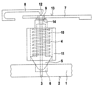
3 0 Figure 1 shows a first embodiment of a positioning device according to the
invention for test elements.
In this preferred embodiment of the present invention, the first switch
component
is a pin sitting on the support surface, and the second switch component is a
3 5 displaceably mounted journal with a sonically tapering end facing towards
the test
element, and the test element has, as position-specific surface configuration,
at
Least one recess receiving the sonically tapering end of the journal.
CA 02478196 2004-08-19
_ 9
The test element l, for example a test strip, is located on a support surface
2. The
pin serving as first switch component 3 sits with one end on the support
surface 2.
The function of the second switch component 4 is assumed by a displaceably
mounted journal with a comically tapering end 5 facing towards the test
element 1.
The first switch component 3 and the second switch component 4 are arranged
parallel to , one another (behind one another in Figure 1 ). The second switch
component 4 can be displaced perpendicular to the support surface 2. The test
element 1 has at least one recess 6 which can receive the comically tapering
end 5
of the second switch component 4. This recess 6 is a position-specific surface
1 o configuration of the test element 1, i.e. the recess 6 is arranged at a
defined
position of the test element 1 so that the test element 1 is located in a
desired
position, for example in a test element analysis system, as soon as the recess
6
receives the comically tapering end 5 of the second switch component 4. To
position the test element I in this desired position, the position of the test
element
1 is changed manually or automatically and pushed under the spring-mounted
second switch component 4 until the second switch component 4 is located over
the recess 6 and is displaced into the latter.
A switch is closed by this displacement of the second switch component 4
relative
2 o to the first switch component 3 serving as reference and sitting on the
support
surface 2, as a result of which the desired positioning of the test element 1
is
signalled.
In the embodiment of the present invention shown in Figure 1, the first switch
2 5 ~ component 3 determines the displacement of a spring plate, which in turn
lifts a
contact spring, and the second switch component 3 transmits its displacement
to
this contact spring, so that an electric switch is closed when the contact
spring 8
and the spring plate 7 touch. Maximum accuracy of positioning is afforded if
the
contact points of the first and second switch components 3, 4 on the contact
spring
3 0 8 and spring plate 7 are very small and are located on a .line arranged
parallel to the
spring rotation axes.
The spring plate 7 and the contact spring 8 are arranged substantially
parallel to the
support surface 2 of the test element I. The first switch. component 3
mechanically
3 5 transmits the reference plane (in the present embodiment the plane of the
support
surface 2} to the spring plate 7. The second switch component 4 acts on the
contact
spring 8 via its end facing away from the test element 1. To do so, the second
switch component 4 engages through an opening 9 in the spring plate 7. When
the
comically tapering end 5 of the second switch component 4 arrives at the
position
CA 02478196 2004-08-19
,_ - 10
of the recess 6 in the test element 1, the second switch component 4 is
displaced by
the spring 10 and also by the spring plate 7 towards the test element l, in
which
process it is guided through the guide sleeve 11. In this way, a contact edge
12 of
the contact spring 8, sitting on the end of the second switch component 4
engaging
through the opening 9 in the spring plate 7, nears the surface 13 in the
spring plate
7. As soon as the contact edge I2 of the contact spring 8 touches the surface
13 of
the spring plate 7, an electric circuit is closed and the attainment of a
defined test
element position is detected. The electric switch is consequently closed
according
to the invention by an electrical contact being established between a spring
plate
displaced by the first switch component and a contact spring displaced by the
second switch component.
The second switch component 4 fixes the test element 1 when it engages in the
recess in the test element l, so that the test element 1 is held in this
position with a
2 5 defined force. Moreover, the test element 1 is very precisely aligned by
the exact
interaction of conical end 5 and, for example, round recess 6, since the
conical end
5 centres the recess 6 about the axis of symmetry of the second switch
component
4 when it is pressed into the recess 6.
2 o The lengths of the first switch component 3 and of the second switch
component 4
are precisely dimensioned in the present invention. In this way, the tolerance
chain
between the mechanical movement and the electrical switching function is kept
as
small as possible and there is minimal hysteresis. If the first switch
component 3,
designed for example as a pin, lies on a support surface 2 of an injection-
moulded
2 5 part, a high-precision switch for serial production can be realized even
with
inexpensive injection-moulding technology. The contact point of the first
switch
component 3 can additionally be used for trimming the switching point in order
to
homogenize parts from several cavities. The first switch component 3
prestresses
the spring plate 7, as a result of which the distance to the overlying contact
spring
3 0 8 is affected.
Figure 2 shows a perspective view of a detail from Figure 1.
This detail shows the interaction of the two switch components 3, 4 with the
spring
3 5 plate 7 and the contact spring 8. The level of the spring plate 7 is
determined by
the first switch component 3 on whose end designed as contact surface it
rests. The
end of the first switch component 3 can be designed for example as a ring-
shaped
end 14 with two elevations surrounding the opening 9 {see Figure 1}, so that
the
spring plate 7 lies on the elevations situated on a line with switch component
4 and
CA 02478196 2004-08-19
a .,
a _ 11 _
parallel to the spring rotation axes.
The second switch component 4 engages through the opening 9 in the spring
plate
7 and lifts or lowers the contact spring 8 depending on the displacement of
the
second switch component 4. When the contact edge 12 of the contact spring 8 is
lifted from the surface of the spring plate 7 and consequently does not touch
this,
the switch formed by the spring plate 7 and the contact spring 8 is in an open
position. When the contact edge 12 lies on the surface of the spring plate 7,
the
switch is closed.
Figure 6 shows a further perspective view of spring plate and contact spring
in
another embodiment of the present invention.
The level of the spring plate 7 is determined by the first switch component 3
which, with a contact surface present on a projection, rests on the spring
plate 7
from above. The second switch component is arranged analogously to the
embodiment of the positioning device according to the invention shown in
Figure
2. The reference numbers for the individual components in Figure 6 correspond
to
those in Figure 2.
In a preferred embodiment of the positioning device according to the invention
with a spring plate 7 and a contact spring 8, in particular according to
Figure 2 or
Figure 6, the first switch component 3 determines the displacement of the
spring
plate 7 by touching the spring plate 7 with a contact surface, the spring
plate being
2 5 prestressed in a direction to the contact surface. The contact surface
touches the
spring plate 7 on the side facing towards the contact spring 8, on the side
facing
away from the contact spring 8, or on both sides of the spring plate 7.
Figure 3 shows a detail of a further embodiment of a positioning device
according
3 o to the invention for test elements.
In this preferred embodiment of the present invention, the first switch
component 3
is a hollow journal which sits on a reference surface of the test element 1
and
which has a comically tapering end facing towards the test element l and with
the
3 5 end having an opening, and the second switch component 4 _ is a pin with a
spherical tip, the pin being spring-mounted in the journal and the spherical
tip
protruding partially through the opening when the spring is extended and being
pressed fully into the journal Then the spring is compressed.
CA 024781962004-08-19
1
The first switch component 3 is here designed as a hollow journal 22 which has
a
comically tapering end 15 with an opening 16. In the inside of the first
switch
component 3 there is a longitudinal bore 17 which opens into a hollow space 18
contained in the comically tapering end 15 and adjoining the opening 16. The
longitudinal bore 17 and the hollow space 18 accommodate the second switch
component 4. The second switch component 4 is in this case a pin 19 with a
spherical tip 20 which is spring-mounted in the longitudinal bore 17 via the
spring
21 and can be displaced along the axis of symmetry of the longitudinal bore
17.
In the extended state, as shown in Figure 3, part of the spherical tip 20 of
the
second switch component 4 protrudes through the opening 16 and past the
comically tapering end 15 of the first switch component 3. This is the case
when
the surface configuration of the test element 1 permits an outward
displacement,
for example due to a depression 23 into which the second switch component 4 is
displaced, while the first switch component 3 sits on a higher base surface of
the
test element 1.
In the compressed state, the spherical tip 20 is pressed fully into the
comically
tapering end 15 of the first switch component 3. This is the case, for
example,
2 o when both the comically tapering end 15 and the spherical tip sit on a
plane bottom
surface of the test element 1.
A high degree of switching sensiti~~ity is achieved by virtue of the non-
linear
relationship between a horizontal movement of the depression during the
2 5 positioning procedure and the vertical displacement of the second switch
component 4.
In this embodiment of the present invention, immersion of the comically
tapering
end 15 into a corresponding depression in the test element 1 effects a
centering of
3 0 the test element, whereas immersion of the spherical tip 20 serves for
positioning.
An important factor for this function is that the force with which the
spherical tip
is pressed down is much less than the force with which the first switch
component 3 is pressed down.
3 5 In this embodiment of the present invention, the surface configuration of
the test
element 1 is a contour which influences the displacement of the pin depending
on
the position of the test element 1. The contour is preferably designed as a
groove
of varying width and depth on the surface of the test element 1. A wide, deep
portion of the groove in this case causes a considerable outward displacement
of
CA 02478196 2004-08-19
- 13 -
the second switch component 4, while a narrow, shallow portion of the groove
allows only a slight outward displacement. Based on the extent of the
displacement
(depending on the displacement of the second switch component 4 relative to
the
first switch component 3), a defined position of the test element 1 can be
detected.
Figure 4 shows a further embodiment of a positioning device according to the
invention for test elements.
This positioning device comprises the two switch components 3, 4 shown in
Figure
3 which are designed as a hollow journal 22 with comically tapering end 15 and
as
a pin i9 with spherical tip 20. Moreover, the positioning device shown in
Figure 4
comprises a spring plate ? and a contact spring 8 which interact in the manner
already described with reference to Figures l and 2. Th.e spring plate 7 lies
on the
end of the journal 22 facing away from the test element l, and the contact
edge 12
of the contact spring lies on the end of the pin 19 engaging through the
opening 9
in the spring plate ?. This results in a difference retainer whose switch
position is
obtained from the difference in displacements of the two switch components 3,
4
sliding on the surface of the test element 1.
2 o Figure S shows a farther embodiment of a positioning device according to
the
invention for test elements.
In this embodiment, the first switch component 3 is a shoulder 24 arranged
alongside the support surface 2 for the test element 1, and the second switch
2 5 component 4 is a displaceably mounted journal with a comically tapering
end 5
facing towards the test element 1. The test element 1 has, as position-
specific
surface configuration, at least one recess 6 receiving the comically tapering
end 5
of the journal. The shoulder 24 is of cuboid shape. It would also be
conceivable,
fox example, for the shoulder 24 to have a step-shaped design. In this
embodiment,
3 o the shoulder 24 and the support surface 2 for the test element 1 are made
in one
piece.
The second switch component 4 is mounted displaceably in the direction of the
arrows 26 and is moved by the spring 10 towards the test element 1. The
electric
3 5 switch is opened as soon as the contact spring 8 is lifted from the spring
plate ? in
the direction of the support surface 2 by the lateral projection 25 of the
second
switch component: This is the case, for example, when the comically tapering
end S
of the journal engages in a recess 6 of the test element, as is shown in
Figure 5, or
when there is no test element 1 present on the support surface 2. The spring
plate ?
CA 02478196 2004-08-19
- 14 -
and the contact spring $ form contacts which are made, for example, as
flexible
metal parts and are electrically connected to a microcontroller (not shown)
for
signal evaluation.
CA 02478196 2004-08-19
- 15 -
List of reference numbers
1 test element
2 support surface
3 first switch component
4 second switch component
comically tapering end of second switch component
6 recess in test element
7 spring plate
8 contact spring
9 opening in spring plate
spring
11 guide sleeve
12 contact edge of contact spring
13 surface of spring plate
14 ring-shaped end of first switch component
1 S comically tapering end of first switch component
16 opening in comically tapering end of journal
17 longitudinal bore
18 hollow space
19 pin
spherical tip
21 spring
22 j ournal
23 depression
24 shoulder
projection
26 arrows
27 projection