Note: Descriptions are shown in the official language in which they were submitted.
CA 02478474 2009-10-27
DELIVERY SYSTEM AND METHOD FOR DEPLOYMENT OF
FORESHORTENING ENDOLUMINAL DEVICES
TECHNICAL FIELD
This invention relates generally to delivery systems for endoluminal devices,
and, more specifically, to delivery systems for endoluminal devices that
undergo a decrease in
length when being expanded from a radially compressed configuration.
BACKGROUND OF THE INVENTION
Endoluminal devices comprise the general category of devices, such as stents,
grafts, combinations thereof commonly referred to as stent-grafts or
endoluminal prostheses, vena
cava filters, and the like, that may be implanted in a body lumen. Endoluminal
devices may be
implanted by so-called "minimally invasive techniques" in which the
prosthesis, restrained in a
radially compressed configuration by a sheath or catheter, is delivered by a
deployment system or
"introducer" to the site where it is required. The introducer may enter the
body through the
patient's skin, or by a "cut down" technique in which the entry lumen, such as
a blood vessel, is
exposed by minor surgical means. When the introducer has been threaded into
the body lumen to
the prosthesis deployment location, the introducer is manipulated to cause the
endoluminal
device to be ejected from the surrounding sheath or catheter in which it is
restrained (or
alternatively the surrounding sheath or catheter is retracted from the
endoluminal device),
whereupon the endoluminal device expands to a predetermined diameter at the
deployment
location, and the introducer is withdrawn.
As referred to herein, "distal" refers to the direction further away from the
insertion point and "proximal" refers to the direction closer to the insertion
point. Endoluminal
devices, such as stents and versa cava filters, may expand by spring
elasticity, balloon expansion,
or by the self-expansion of a thermally or stress-induced return of a memory
material to a pre-
conditioned expanded configuration.
Various types of endoluminal device architectures are known in the art,
including
many designs comprising a filament or number of filaments, such as a wire or
wires, wound or
braided into a particular configuration. Included among these configurations
are braided stents,
such as is described in U.S. Patent No. 4,655,771 to Hans I. Wallsten; the
`771 Wallsten patent is
only one example of many variations of braided architecture known in the art
and thus is not
intended as a limitation of the invention described herein later. Braided
endoluminal devices
tend to be very flexible, having the ability to be placed in tortuous anatomy
and still maintain
patency. The flexibility of braided stents make them particularly well-suited
for treating
aneurysms in the aorta, where often the lumen of the vessel becomes contorted
and irregular both
before and after placement of the stent.
CA 02478474 2009-10-27
-2-
Many braided endoluminal devices experience "foreshortening" when deployed
in a body lumen. Referring now to Figs. lA-IC, showing an exemplary delivery
system 20 of the
prior art, stent 10 may have a first length L(when radially compressed as
shown in Fig. I A and a
second, shorter length L,; when radially expanded, as shown in Fig. 1C. The
"foreshortening
ratio" Lc, L,; can be used as a measure of the relative change in length.
Braided endoluminal
L,,
devices typically have a relatively large foreshortening ratio as compared to
non-braided
endoluminal devices. The foreshortening ratio is a function of compressed
diameter, deployed
diameter, and the braid angle. If these variables are known, the endoluminal
device has a
predictable foreshortening ratio.
Foreshortening may affect the deployment accuracy of endoluminal devices.
Describing delivery system 20 now in more detail, the delivery system
comprises a handle 22, a
tip 24, an inner member 26 attached to the tip and the handle, a pusher 27
positioned proximally
of stent 10, and an outer sheath 28 slidable relative to the inner member and
pusher. Inner
member 26 may have one or more protrusions 25 thereon for engaging the stent
during
deployment, such as are disclosed in U.S. Patent 6,607,551. Stent 10 may be a
braided stent
having a wound end 11, such as is described in U.S. Patent 6,585,758. Delivery
system 20 is
maneuvered into the body lumen (not shown) so that the distal end 12 of stent
10 is aligned with
a desired deployment location 29 in the lumen, as shown in Fig. ]A. Figs. ]A-
IC are shown in
vertical alignment with one another on the page so that desired deployment
location 29 is in the
same horizontal position in all figures for illustrative purposes.
To deploy the stent, outer sheath 28 is retracted in the direction of arrow A
as
shown in Fig. 113. As stent 10 begins to deploy, it also foreshortens, causing
distal end 12 of
stent 10 to be move proximally from the desired deployment location 29. Thus,
after full
deployment as shown in Fig. 1C, continued foreshortening during deployment may
cause the
ultimate resting position of distal end 12 to be a distance d, from the
desired deployment location
29. This distance dL is typically approximately the difference in length
between the radially
compressed length L(, and the expanded length Li;. In some cases, distal end
12 of stent 10 may
frictionally engage a portion of the body lumen in which the stent is being
deployed before the
stent is completely deployed. In such cases, a portion of the length
accounting for the difference
between the compressed length L(: and the expanded length L1; of the stent
will be proximal to the
deployed stent. Thus, even though this distance may be predictable,
practitioners must determine
the correct place to start deployment based upon where the end of the stent is
expected to land
after foreshortening. Deploying such stents with accuracy, therefore, takes
repeated practice and
is prone to error.
CA 02478474 2009-10-27
-3-
It is therefore desirable to minimize the impact of foreshortening of braided
endoluminal devices during deployment so that such endoluminal devices can be
more accurately
deployed.
SUMMARY OF THE INVENTION
The invention therefore provides a delivery system for an endoluminal device,
the delivery system comprising: (a) an endoluminal device having a compressed
configuration;
(b) an outer sheath that radially surrounds the endoluminal device in the
compressed
configuration; (c) a pusher positioned at one end of the endoluminal device;
(d) a linkage in
communication with both the pusher and the outer sheath that coordinates
movement of the outer
sheath in a first direction with simultaneous movement of the pusher in a
second direction
opposite the first direction; and (e) an actuatable clutch mechanism for
preventing the
simultaneous movement of the outer sheath and the pusher when engaged.
The invention also provides a manipulator for a delivery system for an
endoluminal device, the delivery system comprising an outer sheath that
radially surrounds the
endoluminal device in a compressed configuration, a pusher positioned at one
end of the
endoluminal device and an actuatable clutch mechanism for preventing the
simultaneous
movement of the outer sheath and the pusher when engaged, the manipulator
comprising (a) a
first interface for connecting the manipulator in communication with the outer
sheath, (b) a
second interface for connecting the manipulator in communication with the
pusher, a linkage
coupled to the first and second interface for coordinating movement of the
outer sheath in a first
direction with simultaneous movement of the pusher in a second direction
opposite the first
direction, and (c) means for actuating the linkage.
The invention further provides a delivery system adapted to deliver an
endoluminal device from a proximal location outside a lumen to a distal
location inside the
lumen, the delivery system comprising: (a) the endoluminal device in a
compressed
configuration, the endoluminal device having a compressed length (L(,), an
expanded length (L,;),
and a foreshortening ratio L< L greater than 0; (b) a proximally retractable
outer sheath
, L,; L
that radially surrounds the endoluminal device; (c) a distally advanceable
pusher positioned at a
proximal end of the endoluminal device; (d) an actuatable clutch mechanism for
preventing the
simultaneous movement of the outer sheath and the pusher when engaged; and (e)
a rack and
pinion system in communication with both the pusher and the outer sheath that
coordinates
retraction of the outer sheath a first distance of retraction (d,) with
simultaneous advancement of
the pusher a second distance of advancement (d2) of the pusher, the rack and
pinion system
comprising a first rack attached to the outer sheath, a second rack attached
to the pusher, and a
CA 02478474 2009-10-27
-3a-
pair of rotationally-interlocked pinions supported between the first rack and
the second rack, the
pair of rotationally-interlocked pinions comprising a first pinion having a
first diameter (DI)
adapted to interface with the first rack and a second pinion (D2) having a
second, relatively
smaller diameter adapted to interface with the second rack, wherein the gear
ratio (`2-) is
D,
approximately equal to the foreshortening ratio.
The invention also provides a delivery system adapted to deliver an
endoluminal
device from a proximal location outside a lumen to a distal location inside
the lumen, the delivery
system comprising: (a) the endoluminal device in a compressed configuration,
the endoluminal
device having a compressed length (LO, an expanded length (LE), and a
foreshortening ratio
L.L
C greater than 0; (b) a proximally retractable outer sheath that radially
surrounds the
LE
endoluminal device; (c) a distally advanceable pusher positioned at a proximal
end of the
endoluminal device; (d) an actuatable clutch mechanism for preventing the
simultaneous
movement of the outer sheath and the pusher when engaged; and (e) a screw
shaft and traveler
system in communication with both the pusher and the outer sheath that
coordinates retraction of
the outer sheath a first distance of retraction (d1) with simultaneous
advancement of the pusher a
second distance of advancement (d2) of the pusher, the screw shaft and
traveler system
comprising a screw shaft having a first threaded flight having a first pitch
(P1) corresponding to a
number of turns per unit length and a second threaded flight having a second
corresponding pitch
(PA), a first traveler engaged by the first threaded flight and in linear
communication with the
outer sheath, a second traveler engaged by the second threaded flight and in
linear
communication with the pusher; and means for turning the screw shaft., wherein
the ratio of the
first pitch to the second pitch D is approximately equal to the foreshortening
ratio.
z
In one aspect of the invention, the linkage may comprise a rack and pinion
system. The rack and pinion system comprises a first rack in communication
with the outer
sheath, a second rack in linear communication with the pusher, and a pair of
rotationally-
interlocked pinions supported between the first rack and the second rack. The
pair of
rotationally-interlocked pinions comprise a
CA 02478474 2004-08-31
WO 03/084439 PCT/US03/08436
-4-
first pinion having a first diameter adapted to interface with the first rack
and a second pinion having
a second, relatively smaller diameter adapted to interface with the second
rack. A member, such as a
dial with a larger diameter than the first pinion, may be rotationally
interlocked to the pinions for
rotating the pinions to cause the outer sheath and the pusher to
simultaneously move. The system
may comprise a casing disposed about the linkage, and a bearing in the casing
for supporting a shaft
on which the pinions are mounted.
In another aspect of the invention, the linkage comprises a screw shaft having
a first
threaded flight havingaa first pitch and a second threaded flight having a
second pitch. A first
traveler is engaged by the first threaded flight and in linear communication
with the outer sheath. A
second traveler is engaged by the second threaded flight and in linear
communication with the pusher.
The linkage further comprises means for turning the screw shaft. Where the
first threaded flight has
a first pitch (Pi) corresponding to a number of turns per unit length and a
second threaded flight
having a second corresponding pitch (P2), the ratio of the first pitch to the
second pitch (PIIP2) is
approximately equal to the foreshortening ratio.
In some embodiments of the invention, the delivery system may further comprise
a
clutch mechanism for preventing simultaneous movement of the outer sheath and
the pusher when
engaged, including, optionally, indicia for indicating to a user of the
delivery system when to engage
or disengage the clutch mechanism. Other embodiments may comprise a lag
mechanism for
preventing simultaneous movement of the outer sheath and the pusher over a
predetermined travel
distance of the outer sheath.
Another aspect of the invention comprises a manipulator for a delivery system
comprising an outer sheath that radially surrounds a compressed endoluminal
device and a pusher
positioned at one end of the endoluminal device. The manipulator comprises a
first interface for
connecting the manipulator in communication with the outer sheath, a second
interface for connecting
the manipulator in communication with the pusher, a linkage coupled to the
first and second interface
for coordinating movement of the outer sheath in a first direction with
simultaneous movement of the
pusher in a second direction opposite the first direction, and means for
actuating the linkage. The
manipulator may be detachable from the delivery system and reusable, in which
case the manipulator
comprises a material of construction, such as but not limited to stainless
steel, adapted to withstand
prolonged exposure to high temperatures effective to sterilize the manipulator
without being
damaged.
CA 02478474 2004-08-31
WO 03/084439 PCT/US03/08436
-5-
Still another aspect of the invention comprises a method for endoluminal
deployment
of an endoluminal device. The method comprises first introducing a delivery
system from a first
location outside a lumen to a second location inside the lumen. The delivery
system comprises an
endoluminal device in a compressed configuration, an outer sheath that
radially surrounds the
endoluminal device in the compressed configuration, a pusher positioned at a
first end of the
endoluminal device, and a linkage in communication with the pusher and the
outer sheath for
coordinating simultaneous movement of the outer sheath and the pusher. The
second location is a
location at which a second end of the endoluminal device is axially aligned
with a desired target
location on the lumen. The method next comprises deploying the endoluminal
device so that the
second end is implanted in the desired target location. This is effected by
manipulating the linkage to
move the outer sheath in a first direction while simultaneously moving the
pusher in a second
direction opposite the first direction.
Where the first location outside the lumen is a proximal location, the second
location
is a distal location, the first direction is a proximal direction, and the
second direction is a distal
direction, the step of deploying the endoluminal device may comprise
proximally retracting a handle
in communication with the outer sheath or distally advancing a slide in
communication with the
pusher. Where the linkage comprises a rack and pinion system, the step of
deploying the
endoluminal device may comprise manipulating a member that is rotationally
interlocked with the
pinion. Where the stent delivery system comprises a first component comprising
the outer sheath and
the pusher and a second, detachable component comprising the linkage, the
method may comprise
attaching the first component to the second component before introducing the
delivery system into the
lumen. Similarly, the method may comprise the steps of detaching the second
component from the
first component after deployment of the endoluminal device and then
sterilizing the second component
so that it can be reused.
In an embodiment wherein the endoluminal device has a foreshortening ratio
greater
than zero in the first portion and the foreshortening ratio equal to zero in a
second portion and the
system further comprises a clutch mechanism for preventing simultaneous
movement of the outer
sheath and the pusher when engaged, the method comprises deploying the first
portion of the
endoluminal device with the clutch engaged so that there is not simultaneous
movement of the outer
sheath and the pusher, and deploying the second portion of the endoluminal
device with the clutch
released so that there is simultaneous movement of the outer sheath and the
pusher. In an
CA 02478474 2004-08-31
WO 03/084439 PCT/US03/08436
-6-
embodiment wherein the endoluminal device has a foreshortening ratio greater
than zero in a first
portion and a foreshortening ratio equal to zero in a second portion and the
system comprises a lag
mechanism for preventing simultaneous movement of the outer sheath and the
pusher over a
predetermined travel distance of the outer sheath, the method comprises
deploying the first portion of
the endoluminal device without simultaneous movement of the outer sheath and
the pusher and
deploying the second portion of the endoluminal device with simultaneous
movement of the outer
sheath and the pusher.
It is to be understood that both the foregoing general description and the
following
detailed description are exemplary, but are not restrictive, of the invention.
BRIEF DESCRIPTION OF DRAWINGS
The invention is best understood from the following detailed description when
read in
connection with the accompanying drawing. It is emphasized that, according to
common practice, the
various features of the drawing are not to scale. On the contrary, the
dimensions of the various
features are arbitrarily expanded or reduced for clarity. Included in the
drawing are the following
figures:
Fig. 1A depicts a partial longitudinal section of an exemplary delivery system
of the
prior art for deploying a foreshortening-prone stent of the prior art;
Fig. 1B depicts the delivery system of Fig. 1A in a partially deployed
configuration;
Fig. 1C depicts the delivery system of Fig. 1A after the stent has been fully
deployed;
Fig. 2A depicts a partial longitudinal section of an exemplary delivery system
of the
present invention;
Fig. 2B depicts the delivery system of Fig. 2A in a partially deployed
configuration;
Fig. 2C depicts the delivery system of Fig. 2A after the stent has been fully
deployed;
Fig. 3A is a proximal view of an exemplary embodiment wherein the pinions
shown
in Fig. 2A have a dial rotationally interlocked to them;
Fig. 3B is a proximal view of an exemplary embodiment wherein the pinions
shown
in Fig. 2A have a crank rotationally interlocked to them;
Fig. 4 is a perspective view of an exemplary linkage comprising a screw drive
and a
pair of travelers;
CA 02478474 2004-08-31
WO 03/084439 PCT/US03/08436
-7-
Fig. 5 is a cross-sectional view of a portion of an exemplary delivery system
having a
clutch mechanism; and
Fig. 6 depicts a partial longitudinal section of an exemplary delivery system
of the
present invention having a lag mechanism.
DETAILED DESCRIPTION OF INVENTION
The invention will next be illustrated with reference to the figures wherein
similar
numbers indicate the same elements in all figures. Such figures are intended
to be illustrative rather
than limiting and are included herewith to facilitate the explanation of the
apparatus of the present
invention.
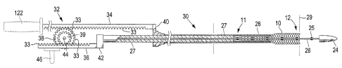
Referring now to Figs. 2A-2C, there is shown an exemplary delivery system 30
of
this invention in various stages of deployment. Delivery system 30 comprises
stent 10 in its
compressed configuration, outer sheath 28 that radially surrounds the stent,
pusher 27 positioned at
the proximal end 11 of the stent, and a linkage 32 in communication with both
the pusher and the
outer sheath. Linkage 32 coordinates proximal retraction of outer sheath 28
with simultaneous distal
advancement of pusher 27. Also shown in Figs. 2A-2C is inner member 26,
attached to an interface
42 at its proximal end and extending axially through stent 10 and pusher 27 to
a connection with tip
24 at its distal end.
As shown in Figs. 2A-2C, linkage 32 comprises a rack and pinion system having
intermeshing teeth 33. The rack and pinion system comprises a first rack 34 in
linear communication
with outer sheath 28, a second rack 36 in linear communication with the pusher
27, and a pair of
rotationally-interlocked pinions 38 and 39 supported between the first rack
and the second rack.
Pinion 38 has a first diameter Di and is adapted to interface with the rack
34. Pinion 39 has a second
diameter D2 that is relatively smaller than first diameter Di, and is adapted
to interface with the rack
36. It should be noted that the rack and pinion system shown in Figs. 2A-2C is
merely one
exemplary embodiment, and other rack and pinion systems may also be devised to
provide a similar
effect. For example, the pinions may have a common diameter and may be mounted
on separate
shafts, with a gear mechanism, belt and sheave, or chain and sprocket
mechanism provided between
the pinions to provide the differential motion between the racks.
The term "linkage" is used herein to denote any mechanism that links together
the
motion of outer sheath 28 and pusher 27. Thus, although a rack and pinion
system is shown herein,
CA 02478474 2004-08-31
WO 03/084439 PCT/US03/08436
-8-
other types of linkages may be provided within the scope of this invention,
including but not limited
to those discussed specifically herein below.
By "in linear communication with" it is meant that the each rack 34 and 36
moves
linearly in concert with the sheath 28 or the pusher 27, respectively, such
that movement of the
respective rack in one linear direction will move the sheath or pusher in the
same linear direction.
Although rack 34 is shown with a direct connection to sheath 28 at interface
40 and rack 36 is shown
with a direct connection to pusher 27 at interface 42 in Figs. 2A-2C, the
respective racks may be
indirectly connected to the sheath or pusher through one or more intermediate
elements. Thus, the
terminology "in linear communication with" has been chosen to reflect that no
direct connection
between the racks and the sheath or pusher is required. Preferably, interfaces
40 and 42 are
configured to be attached to sheath 28 and pusher 27 at a location such that
the interfaces and linkage
32 can remain outside of the body lumen during deployment.
By "rotationally interlocked" it is meant that pinions 38 and 39 are connected
in such
a way that they rotate the same degree of revolution in the same direction
simultaneously. For
example, as shown in Figs. 2A-2C, the pinions are mounted on the same shaft 44
in a way that one
full revolution of the shaft will coincide with one full revolution of both
pinions 38 and 39. The
pinions may be bonded together or may be machined from a single integral
piece, or the shaft may be
keyed and each pinion may be independent from one other but keyed similarly to
the shaft. In an
alternative embodiment, the pinions may be mounted on separate shafts, with
other methods of
rotationally interlocking them, such as a gear train or drive belt or chain
that provides for one full
revolution of one pinion to translate to one full revolution of the other
pinion. It should be
understood that any number of mechanisms may be devised for providing
rotationally interlocking
pinions, all of which are within the scope of the present invention.
The simultaneous retraction of outer sheath 28 and advancement of pusher 27
may be
accomplished by any of a number of methods and structures, some examples of
which are shown in
Fig. 2B with dashed lines, and in Figs. 3A and 3B. As shown in Fig. 2B, a
handle 122 may be
attached to rack 34 or otherwise in linear communication with outer sheath 28
so that proximal
retraction of the handle actuates the linkage. Similarly, a slide 46 may be
attached to rack 36 or
otherwise in linear communication with pusher, 27, so that distal advancement
of the slide will actuate
the linkage. Although both handle 122 and slide 46 are both shown in Fig. 2B,
embodiments of the
invention may have none, both, or only one of these means. A member in
rotational communication
CA 02478474 2010-09-10
12056-1
-9-
with pinions 38 and 39, such as dial 48 shown in Fig. 3A or crank 49 shown in
Fig. 3B,
may also or instead be used for directly rotating at least one of the pinions,
thereby
actuating the linkage. Suitable members are not limited to dial 48 and crank
49, but may
include any means known in the art for actuating a pinion, such as for example
but not
limited to, a pistol grip mechanism such as disclosed in U.S. Patent No.
5,968,052 to
Sullivan and DeVries. By "in rotational communication" with pinions 38 and 39
it is
meant that rotation of the member also causes pinions 38 and 39 to rotate. A
full
revolution of the first member may translate to less than, equal to, or
greater than a full
revolution of a second member in rotational communication with the first
member.
Accordingly, a dial or crank may be rotationally interlocked to the pinions as
shown
in Figs. 3A and 3B so that one revolution of the dial or crank corresponds to
one rotation
of the pinions, or the dial or crank may include a transmission such as a
gearing
mechanism that provides mechanical advantage, such as for example a dial
geared to the
pinion such that a full rotation of the dial results in less than a full
rotation of the pinion.
Conversely, if it is desired to reduce the amount of travel of the dial
relative to the
pinion, the transmission may translate less than a full rotation of the dial
to a full rotation
of the pinion. The diameter of the dial or diameter of rotation of the crank
may also be
used to provide mechanical advantage or to reduce travel. The "diameter of
rotation" for
a crank is twice the radial distance r, of the crank from the centerpoint of
the shaft
rotated by the crank, as shown in Fig. 3B. For example, dial 48 may have a
diameter D3
or crank 49 may have a diameter of rotation 2r1 greater than diameter DI of
the largest
pinion, as shown in Figs. 3A and 3B, respectively. Where the dial is
rotationally
interlocked with the pinions, the larger diameter provides mechanical
advantage.
Conversely, a dial with a diameter smaller than diameter D, enables the user
to retract
outer sheath 28 a given linear distance greater than fitD3 by moving the dial
a
circumferential distance 0itD3, where is the percentage of a full revolution
traveled by
dial 48.
Referring now to Fig. 4, there is shown an alternative linkage embodiment 50
of the
present invention comprising a screw shaft 52 having a first threaded flight
54 for
engaging a first traveler 56, and a second threaded flight 58 for engaging a
second
traveler 60. A handle 62 may be used for manipulating the linkage. As shown in
Fig. 4,
CA 02478474 2010-09-10
12056-1
-9a-
when handle 62 is turned clockwise (as viewed from the handle end of the
screw) in the
direction of arrow Z, flight 54 moves traveler 56 in the direction of arrow X,
whereas
flight 58 moves traveler 60 in the direction opposite arrow X. Furthermore,
flight 54 has
a wider pitch than flight 58, so that traveler 56 moves a greater distance
CA 02478474 2004-08-31
WO 03/084439 PCT/US03/08436
-10-
that traveler 60. Although illustrated herein with a single handle 62 that may
be turned by the user, it
should be recognized that any means for rotating screw shaft 52 may be
provided. For example,
screw shaft 52 may be engaged by a transmission for translating linear motion
in any plane or
rotational motion about any axis to rotational motion of screw shaft 52, with
or without mechanical
advantage, including engagement by, for example, the pistol grip mechanism
referred to herein.
For any type of linkage used in the present invention, a preferred embodiment
is for
the linkage to coordinate a first distance (di) of proximal retraction of the
outer sheath to a second
distance (d2) of distal advancement of the pusher. As shown in Fig. 2C, outer
sheath 28 needs to
retract a distance di equal to the expanded length (LE) of stent 10. By
contrast, pusher 27 needs only
to travel a distance d2 equal to the compressed length (Lc) minus the expanded
length (LE). Therefore
the ratio of the second distance to the first distance d is equal to the
foreshortening ratio.
1 )
For the rack and pinion system shown in Figs. 2A-2C, the circumferential
travel
O7rDi of pinion 38 translates to distance di and the circumferential travel
OlrD2 of pinion 39 translates
to distance d2 for an appropriate value of . Accordingly, the gear ratio D2IDi
is also preferably
equal to the foreshortening ratio. Similarly, for the screw drive embodiment
50 shown in Fig. 4,
where Pi equals the pitch of flight 54 represented as a number of turns per
unit length and P2 equals
the corresponding pitch of flight 58. Thus, the distance di = n/Pi, where n is
the number of full
turns of handle 62, and d2=n/P2. Accordingly, the ratio of Pi/P2 is equal to
the foreshortening ratio
d2/di.
The linkages of the present invention may comprise a separable component from
the
component comprising the outer sheath and pusher, or an inseparable component.
As such, the
linkage component may be described as a "manipulator" for a delivery system
because it is used to
manipulate the delivery system during deployment. The manipulator may comprise
other components
in addition to the linkage, but at a minimum, referring to the embodiment
shown in Figs. 2A-2C, the
manipulator comprises linkage 32, interface 40 for connecting the manipulator
in communication with
the outer sheath 28, interface 42 for connecting the manipulator in
communication with pusher 27,
and means for actuating the linkage. The means for actuating the linkage may
be any means known
in the art, particularly those discussed above such as handle 122 or slide 46
as shown in Fig. 2B, or
dial 48 or crank 49 as shown in Figs. 3A and 3B, respectively. Finally,
although a rack and pinion
CA 02478474 2004-08-31
WO 03/084439 PCT/US03/08436
-11-
type linkage is shown herein by way of example, any type of linkage known in
the art may be used,
such as a belt and pulley system.
Where the manipulator is detachable from the rest of the delivery system, it
may also
be reusable. In such embodiments, it is desirable for the manipulator to
comprise a material of
construction adapted to withstand exposure to a predetermined temperature for
a predetermined
amount of time effective to sterilize the manipulator without the manipulator
being damaged. For
example, hospitals may heat items to be sterilized in an autoclave set to an
effective temperature for
an effective amount of time known to sterilize the items. The combination of
time and temperature is
well-known in the art, as are materials of construction suitable for items
that undergo such
sterilization procedures. Stainless steel is a typical material used, but the
invention is not limited to
any particular material, and therefore any suitable material known in the art
may be used.
Manipulators not intended for reuse may comprise materials less expensive than
stainless steel, as are known in the art, including materials such as plastics
that can readily be
incinerated in hospital incinerators. Although non-reusable manipulators may
still be detachable if
desired, for example for shipping or packaging considerations, manipulators
that are integral to the
rest of the stent delivery system may offer an advantageous reduction in
assembly time and
correspondingly reduced potential for assembly errors or failures at the
interfaces.
The delivery system of the present invention lends provides a unique method
for
delivery of an endoluminal device. The method comprises the steps of first
introducing the delivery
system into a body lumen and aligning the first end of the endoluminal device
to be deployed, which
in Fig. 2A is the distal end 12, with a desired target location 29 on the
lumen or a previously
endoluminal device (not shown). The method then comprises deploying the
endoluminal device with
the second end in the desired target location by manipulating the linkage to
move the outer sheath in a
first direction while simultaneously moving the pusher in a second direction
opposite the first
direction. Although as shown in Figs. 2A-2C, the stent is being deployed from
a proximal location
outside the lumen into a distal location, and the outer sheath is proximally
retracted while the pusher
is distally advanced, the method is not limited to any particular direction of
deployment. The step of
manipulating the linkage may be initiated by retracting handle 122 or
advancing slide 46 as shown in
Fig. 2B, by turning dial 48 or crank 49 as shown in Figs. 3A and 3B,
respectively, or by any other
means. Where the linkage provides mechanical advantage, the linkage may be
manipulated using less
force than the sum of forces required to move the outer sheath and the pusher
without the linkage.
CA 02478474 2004-08-31
WO 03/084439 PCT/US03/08436
-12-
Although the method may be useful for the implantation of any endoluminal
device,
the method is particularly useful for an endoluminal device having a
foreshortening ratio greater than
0. In such case, the method implants end 12 of the endoluminal device
precisely at the desired target
location 29, unlike methods of the prior art where the foreshortening of the
endoluminal device
causes the distal end to be implanted proximally of the desired target
location. As discussed herein,
the preferred method coordinating a first distance of proximal retraction (di)
of outer sheath 28 with a
second distance (d2) of distal advancement of pusher 27 wherein the second
distance divided by the
first distance d2 is approximately equal to the foreshortening ratio of the
endoluminal device. It
i
should be appreciated that although the illustrations and accompanying text
herein refer to a stent, the
introducer of the present invention may be used for deploying any type of
endoluminal device,
including but not limited to stents, grafts, prostheses, vena cava filters,
and the like.
Where the component comprising the linkage is detachable from at least the
outer
sheath and the pusher, the method further comprises attaching the first
component to the sheath and
pusher component prior to introducing the stent delivery system into the
lumen. Wherein the linkage
component is reusable, the method further comprises the steps of detaching the
second component
from the first component after deployment of the stent and then sterilizing
the linkage component.
Some stent or filter embodiments may comprise a combination of foreshortening
and
non-foreshortening sections. Thus, for example, deployment of one longitudinal
section of the stent
may benefit from the linkage between pusher and outer sheath as discussed
above, whereas
deployment of an adjacent longitudinal section may not benefit from such a
linkage, and may actually
suffer from use of such system. Thus, for this and other reasons, it may be
desirable to provide a
clutch mechanism that prevents engagement of the linkage when actuated. In
other cases, the system
may have structure features tailored to prevent advancement of the pusher
simultaneously with
retraction of the outer sheath at certain points during deployment. Exemplary
such systems are
described below, but the invention is not limited to any particular embodiment
of these
functionalities.
Referring now to Fig. 5, there is shown a cross-sectional view of a portion of
an
exemplary delivery system 500 having a clutch mechanism. System 500 comprises
a two part casing
502, comprising snap-together halves 502a and 502b. Ball bearing 504 having
balls 503 is attached
to half 502a, and shaft 44 is supported by the ball bearing. Although
illustrated with a ball bearing,
CA 02478474 2004-08-31
WO 03/084439 PCT/US03/08436
-13-
any type of bearing may be used. Spring 506 biases pinions 38 and 39 into a
position in engagement
with racks 34 and 36, respectively. Clutch button 508 is biased by spring 510
outwardly from casing
half 502b, with stops 511 keeping the button from being fully ejected by the
spring from the casing.
Stops 511 may be set screws, a molded portion of the button, or any member
functional to act as a
stop but still provide for assembly of button 508 in the casing 502.
Depressing button 508 inwardly
in the direction of arrow B causes the inward-most portion of prongs 509 of
button 508 to engage
pinion 39 and push both pinions out of engagement with the racks for as long
as the clutch button is
depressed. Releasing button 508 allows spring 506 to force the pinions back
into engagement with
the racks. Casing half 502b has an indentation 514 concentric with button 508
so that button 508 can
be depressed almost flush with casing 502. Button 508 may be circular, square,
or any shape
desired. Prongs 509 may comprise prongs with circular or square cross-
sections, circumferential
portions of a cylinder, or any shape known in the art.
Casing 502 is also shown with support brackets 512 for slidably supporting the
racks.
By "slidably supporting" it is meant that the brackets do not interfere with
the distal and proximal
sliding of the racks. It should be understood that even embodiments without a
clutch mechanism may
have a casing that supports the pinion shaft and that has brackets to support
the travel of the racks.
Such a casing may be a complete enclosure as shown in Fig. 5, or may provide
only enough structure
to support the racks and/or pinions. The invention is not limited to the
particular features of the
casing, nor to embodiments having casings. It should be understood, however,
that typically some
structural element is present to support the pinions in the desired position
relative to the racks, and
such supportive features have been omitted from Figs. 2A-4 for simplicity of
illustration. Such
supportive features may comprise any structural elements known in the art.
Fig. 6 illustrates an exemplary lag system 600. Lag system 600 comprises
features
similar to those found in Figs. 2A-2C, except that a longitudinal portion 602
of rack 634 is without
teeth 33. Thus, when rack 634 attached to outer sheath 28 is retracted over
portion 602, there is
nothing to engage pinion 38, and thus neither pinion 39 or 38 rotate until the
proximal-most tooth 33a
of rack 634 engages pinion 38. Thus, distal advancement of pusher 27 can be
said to "lag" the
proximal retraction of sheath 28. Toothless portion 602 may be tailored to
have a length sufficient to
deploy the corresponding non-foreshortening portion of the endoluminal device
to be deployed. The
toothless portion may also be on one of both of the pinions, if the conditions
favor such an
arrangement. Where the pinions experience more than,a single revolution over
the course of fully
CA 02478474 2004-08-31
WO 03/084439 PCT/US03/08436
-14-
deploying the endoluminal device, however, a toothless portion of the rack may
be most
advantageous. The toothless portion 602 may be at the proximal end of the
rack, a distal end of the
rack, or in the middle of the rack, and the rack may have more than one
toothless portion. The
structural features of the lag system are preferably tailored to match the
features of the endoluminal
device to be deployed.
One advantage of a lag system over a clutch system, is that the rack can be
designed
so that the practitioner merely pulls proximally on rack 634, without having
to be concerned about
timing the engagement and release of the clutch. For clutch systems, however,
the rack may be
provided with indicia visible to the practitioner at the proximal end to
indicate when to pull in the
clutch and when to release. For example, in the clutch system, as rack 34 is
retracted, a portion
proximally protruding from the proximal end of the casing may comprise one
color to indicate
engaging the clutch and another color to indicate releasing the clutch. Thus,
as the rack is retracted,
the color of the rack emerging from the casing may indicate to the
practitioner whether to engage or
release the clutch. Similarly, dial 48 as shown in Fig. 3A may have color-
coded portions or other
indicia to indicate when to release and when to engage the clutch. In a crank
system, the practitioner
may be provided with instructions as to when to engage and disengage the
clutch based on how many
degrees the crank is turned. It should be recognized that for lag systems to
work with respect to the
dial or crank embodiments of Figs. 3A or 3B, respectively, the pinions are
typically the members
with toothless portions. A lag system for the screw shaft embodiment shown in
Fig. 4 can be
approximated by having a very close pitch for a predetermined portion of one
of the flights.
Although illustrated and described herein with reference to certain specific
embodiments, the present invention is nevertheless not intended to be limited
to the details shown.
Rather, various modifications may be made in the details within the scope and
range of equivalents of
the claims and without departing from the spirit of the invention.