Note: Descriptions are shown in the official language in which they were submitted.
CA 02478483 2004-09-08
Plate
The invention concerns a plate, in particular a motor vehicle licence
plate, as set forth in the classifying portion of claim 1.
A plate of that kind is known for example from German utility model
No 299 11 348.5. Described therein is a metal plate which is coated with an
i0 electroluminescence structure and which is not only a carrier but at the
same time also a base electrode of the electroluminescence structure. That
admittedly affords a very simple structure but it suffers from a number of
disadvantages.
On the one hand such an arrangement cannot be used for plates in
i5 which the carrier comprises a non-conducting plastic material.
Further problems are involved in reliably electrically contacting the
extremely thin, transparent cover electrode disposed on the top side of the
electroluminescence structure. The alternating current which flows by way
of an electroluminescence flat capacitor increases, the greater the surface
2o area covered by that flat capacitor. Having regard to the size of a motor
vehicle licence plate, serious difficulties are involved in feeding the
required
current into the extremely thin cover electrode in such a way that this does
not result in excessively great current densities which can lead to the cover
electrode being locally burnt through or vaporised. In addition it is
25 necessary to ensure that, when contacting the cover electrode the
dielectric
layers which are disposed therebeneath are not pierced, which would result
in a short-circuit and thus functional failure of the electroluminescence flat
capacitor.
In addition the entire arrangement is exposed to extreme
30 environmental influences with a high level of mechanical and chemical
loading (severe vibration, . corrosive environment, high moisture content
and so forth). That also applies in particular for the current connection
terminals of the two electrodes of the electroluminescence flat capacitor, at
1
CA 02478483 2004-09-08
which no high and/or increasingly worsening transition resistances should
occur.
Accordingly the object of the present invention is to provide a plate
of the kind set forth in the opening part of this specification, in the
production of which a carrier of metal or plastic material can be selectively
used and in which at any event simple and reliable contacting of the
electrodes of the flat capacitor, in particular the thin cover electrode, is
guaranteed.
To attain that object the invention provides the features recited in
i0 claim 1. Those measures are based on the realisation that it is
advantageous to forego the use of the carrier as the base electrode. That
means that admittedly, the structural simplification known from the quoted
state of the art is no longer enjoyed, but at the same time a series of
advantages is also attained.
A first of those advantages is that the electrical conductivity of the
carrier is no longer an important consideration so that, in the production of
such a plate, it is possible to use either a metal carrier or a plastic
carrier
selectively and in a manner adapted to the respective situation of use.
Another important advantage is that not only one or more base
2o electrodes of one or more flat capacitors but also at least one feed-in
line
v
can be produced in respective electrically mutually insulated relationship
from the electrically conducting layer which initially covers the further
insulating layer over the entire surface area, in which case the feed-in line,
in the finished layer structure, is covered over from above by the thin cover
electrode in such a way that there is an electrically well conducting contact.
The feed-in line can be taken almost around the entire peripheral,edge of
the base electrode arrangement so as to afford an elongate narrow
conductor strip, by way of which the current flowing through the flat
capacitor arrangement can be fed into the cover electrode with a
sufficiently low current density without the risk of damage.
It is particularly preferable for the further insulating layer used to be
a plastic sheet or film which is applied to the carrier in a condition of
adhering firmly thereto and which, on its side remote from the carrier,
2
CA 02478483 2004-09-08
carries the electrically conducting layer, for example in the form of a copper
coating, from which the desired conductor track structures can be produced
by known etching procedures.
Preferably that plastic film has at least one tongue which projects
beyond the edge of the carrier and on which the connection conductor
tracks for the base electrode arrangement and the feed-in line are
provided. The tongue can be folded over in the mounted condition on to the
rear side of the carrier and there contacted, by means of one of the known
processes.
A further aspect of particular significance is that both the electrically
conducting layer from which the base electrode arrangement and the feed-
in line are produced and also the extremely thin cover electrode are readily
capable of also taking part in subsequent mechanical deformation, which is
effected for example by a stamping or embossing operation, of the initially
flat carrier, without that involving impairment of the operational capability
of the electroluminescence arrangement.
In particular it is possible to emboss into the carrier from the rear
depressions which provide that raised portions are produced on the side of
the carrier which is towards the person viewing the arrangement, which
raised portions are for example in the shape of symbols to be represented
and are covered with a color which is opaque in relation to the light of the
electroluminescence arrangement so that the symbols formed in that way
appear dark in front of an illuminating background.
The overall arrangement can be covered with a further film or sheet
which is moisture-tightly connected at the edges to the carrier and which
protects the electroluminescence structures in relation to moisture and
mechanical damage.
Advantageously, that protective cover may also include
retroreflecting components so that, when the electroluminescence
arrangement is switched off, under incident external light, a plate designed
in that way has a high reflection capability.
These and further advantageous configurations of a plate according
to the invention are set forth in the appendant claims.
3
CA 02478483 2004-09-08
The invention is described hereinafter by means of an embodiment
with reference to the drawing in which:
Figure 1 is a highly diagrammatic view of a typical layer structure for
a self-illuminating plate according to the invention, and
Figure 2 is a diagrammatic plan view of a motor vehicle licence plate
of that layer structure.
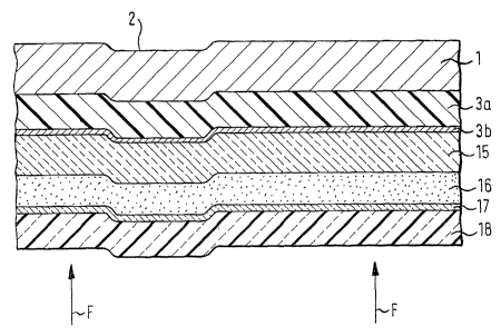
In Figure 1 in which the arrows F show the main direction of view of
the person viewing the arrangement, the individual layers are shown on a
greatly enlarged scale. For the sake of clarity of the drawing individual ones
io of the layers which in actual fact are particularly thin are shown on a
greatly enlarged scale.
Disposed 'at the back' in the viewing direction F, that is to say at the
location most remote from the person viewing the arrangement, is the
deformable carrier 1 which can comprise a metal or plastic plate member
i5 which is deformable by a mechanical embossing or stamping operation. In
the illustrated embodiment the carrier 1 has a depression 2 which is
embossed from the rear and which provides that a corresponding raised
portion is to be found on its front side which is towards the person viewing
the arrangement. It should be particularly pointed out that the deformation
2o of the carrier 1, which leads to that depression 2 and further depressions
and/or raised portions, does not have to be effected prior to application of
the layer structure described in detail hereinafter. Rather, it is possible
for
the carrier 1 with the complete layer structure to be produced in a finished
condition as a 'blank' which can then subsequently be mechanically
25 stamped or embossed in any manner and/or deformed in any other fashion.
That is of significance in particular in regard to the production of
motor vehicle licence plates in which firstly blanks of that kind are produced
in large numbers by specific manufacturers and sold to the 'plate makers'
who, upon customer order, after allocation of a specific motor vehicle
30 registration, stamp or emboss that registration into the blank from the
rear, in which case the raised regions on the front side are colored black.
The plate described in the present application is readily suitable for that
operating procedure.
4
CA 02478483 2004-09-08
Applied to the carrier 1 over the entire surface area thereof is an
insulating plastic film or sheet 3a which on its front side towards the person
viewing the arrangement is provided initially over its entire area with a
layer 3b of a material which is a good electrical conductor, for example
copper.
As can be seen in particular from Figure 2 that plastic film 3a has a
tongue 5 which is shown on a greatly enlarged scale in Figure 2 and which
projects beyond the outline contour of the carrier 1 and which is initially
also coated over its surface area with an electrically conducting material 3b.
Two mutually separate and electrically insulated surface regions are
produced from that electrically conducting coating, those surface regions
being shown by dashed and dashed-dotted lines respectively in Figure 2.
One of the two surface regions forms a base electrode 7 which
covers almost the entire front face of the carrier 1 and defines the size and
shape of the surface which lights up in operation of the finished structure.
As will be seen the base electrode 7 is directly electrically conductingly
connected to a connecting conductor 8 provided on the tongue 5.
Extending around the base electrode 7 is a feed-in line 10 which is
connected to the connecting conductor 9 and which, as will be described in
still greater detail hereinafter, serves for the power supply for the
transparent cover electrode of the flat capacitor forming the
electroluminescence structure.
Both the width of the feed-in line 10 and also the spacings thereof
relative to the edge of the carrier 1 on the one hand and the edge of the
base electrode 7 on the other hand are shown on a greatly enlarged scale
in Figure 2 for the sake of enhanced clarity of the drawing. In practice the
edge of the base electrode 7 can extend substantially further to the edge of
the carrier 1 so that virtually its entire front face which is towards the
person viewing the arrangement is illuminated.
An exception from this is only formed by the region 12 which is
shown entirely at the left . in Figure 2 and which involves the blue region
which is provided on European licence plates, with the ring of stars and the
nationality identification.
5
CA 02478483 2004-09-08
In accordance with the invention it is readily possible for that region
also to be designed to be illuminated.
In that case the base electrode 7 is then extended by a
corresponding distance towards the left. In that respect, a narrow space
always still remains there so that the feed-in line 10 can extend around the
base electrode 7.
As can also be seen from Figure 1 the electrically conducting coating
3b is covered completely by an insulating layer 15 which forms a main part
of the dielectric of the flat capacitor to be formed and which is preferably
io colored with a white pigment which admittedly itself does not light up but
which reflects towards the viewer the light produced in operation by the
pigment layer 16 covering it, and thus provides for a marked improvement
in brightness.
The insulating layer 15 can be used in the production of the blank to
produce the etching mask which covers the surface regions 7, 8, 9, 10 of
the electrically conducting coating 3b of the plastic film 3a so that, in an
etching step, only the intermediate spaces which remain free therebetween
are etched away and thus the surface regions 7 and 8 on the one hand and
the surtace regions 9 and 10 on the other hand are electrically insulated
from each other.
In comparison the pigment layer 16 preferably only covers the
surface region of the base electrode 7 as in fact all other regions are not to
be adapted to light up.
Prior to application of the extremely thin transparent cover electrode
17 (see Figure 1), the part of the insulating layer 15 which covers the feed-
in line 10 is removed so that the cover electrode 17 can involve intimate
contact, providing good electrical conduction, with the feed-in line 10.
The purpose of that feed-in line is to feed in the alternating current
which flows to the cover electrode 17, over as large a surface area as
3o possible, in order to minimise local current densities. Otherwise, by
virtue
of the extremely small thickness of the cover electrode 17, there would be
the risk of at least local damage due to burning or vaporisation because of
an excessively high current density.
6
' CA 02478483 2004-09-08
As already indicated the base electrode 7, the insulating layer 15, the
pigment layer 16 and the transparent cover electrode 17 form a flat
capacitor to which in operation an ac voltage for example of the order of
magnitude of between 80 V and 100 V and of a frequency of the order of
magnitude of 400 Hz can be applied in order to cause the pigment layer 16
to light up.
The overall arrangement is covered over its entire area by a
transparent plastic film or sheet 18 which is connected to the carrier in
moisture-tight relationship at the outside edges of the carrier in order to
protect the flat capacitor from moisture and which can contain
retroreflecting components.
The tongue 5 which projects upwardly in Figure 2 can be provided at
any other location on the carrier. In the mounted condition it is folded over
rearwardly on to the rear side of the carrier 1 and can there be connected
by soldering or crimping or another known contacting process to connecting
lines which lead on further elsewhere or directly to the actuating device
which produces the ac voltage required for operation of the self-illuminating
licence plate, from the motor vehicle on-board do voltage system.
In principle it is also possible to provide in the left-hand side region
12 a separate flat capacitor, the base electrode of which is separate from
the base electrode 7 but which can have a common cover electrode with
the other flat capacitor. The base electrode of that further flat capacitor
then has to be passed out by way of its own connecting line (not shown) on
the tongue 5 so that separate actuation is possible and each of the two
regions can be switched on and off separately.
As an alternative to the above-discussed embodiment by~ way of
example of the invention the plastic t=Ilm 3a can also carry a plurality of
electrically conducting coatings which are electrically insulated from each
other by interposed insulating layers and from which mutually different
3o electrically conducting regions, in particular connecting conductor tracks,
are produced, in order to make it possible for more than two flat capacitors
provided on the surface of the licence plate, which can be arranged in side-
7
CA 02478483 2004-09-08
by-side relationship or one behind the other in the direction of view F also
to be actuated separately from each other.
8