Language selection

Search

Patent 2478581 Summary

Third-party information liability

Some of the information on this Web page has been provided by external sources. The Government of Canada is not responsible for the accuracy, reliability or currency of the information supplied by external sources. Users wishing to rely upon this information should consult directly with the source of the information. Content provided by external sources is not subject to official languages, privacy and accessibility requirements.

Claims and Abstract availability

Any discrepancies in the text and image of the Claims and Abstract are due to differing posting times. Text of the Claims and Abstract are posted:

  • At the time the application is open to public inspection;
  • At the time of issue of the patent (grant).
(12) Patent: (11) CA 2478581
(54) English Title: INTERVERTEBRAL IMPLANT
(54) French Title: IMPLANT INTERVERTEBRAL
Status: Deemed expired
Bibliographic Data
(51) International Patent Classification (IPC):
  • A61F 2/44 (2006.01)
  • A61B 17/80 (2006.01)
(72) Inventors :
  • MATHIEU, CLAUDE (Switzerland)
  • CAIN, CHRIS M. J. (Australia)
(73) Owners :
  • SYNTHES USA, LLC (United States of America)
(71) Applicants :
  • SYNTHES (U.S.A.) (United States of America)
(74) Agent: OSLER, HOSKIN & HARCOURT LLP
(74) Associate agent:
(45) Issued: 2010-01-19
(86) PCT Filing Date: 2002-02-19
(87) Open to Public Inspection: 2003-08-28
Examination requested: 2007-02-16
Availability of licence: N/A
(25) Language of filing: English

Patent Cooperation Treaty (PCT): Yes
(86) PCT Filing Number: PCT/CH2002/000099
(87) International Publication Number: WO2003/070128
(85) National Entry: 2004-09-02

(30) Application Priority Data: None

Abstracts

English Abstract


The intervertebral implant is in the form of a three-dimensional structure
(10) comprising (a) a top side (1) and an underside (2) which are designed to
rest
against the end plates of two adjacent vertebras, (b) a left side face (3) and
a right side
face (4), (c) a front face (5) and a rear face (6), (d) a horizontal center
plane situated
between the top side (1) and the underside (2), (e) a vertical center plane
(8) situated
between the left side face (3) and the right side face (8) and (f) a plurality
of boreholes
(9) passing through the implant structure (10) that are designed to receive
longitudinal
affixation elements (20), the axes (19) of said elements intersecting the
horizontal
center plane (7). At least one of the boreholes (9) is designed in a manner
that the
affixation element (10) received in it can be rigidly connected to the
intervertebral
implant. Said connection is implemented using a thread or by matching conical
surfaces.


French Abstract

L'invention concerne un implant intervertébral sous forme de corps tridimensionnel (10) comprenant: a) une face supérieure (1) et une face inférieure (2), lesquelles sont conçues pour être mises contre les faces terminales de deux vertèbres contiguës; B) une face latérale gauche (3) et une face latérale droite (4); C) une face avant (5) et une face arrière (6); D) un plan médian (7) horizontal situé entre la face supérieure (1) et la face inférieure (2); E) un plan médian (8) vertical situé entre la face latérale gauche (3) et la face latérale droite (4); et F) une pluralité de forages (9) traversant le corps (10), lesquels servent à réceptionner des éléments de fixation (20) longitudinaux dont les axes (19) coupent le plan médian (7) horizontal. Au moins un des forages (9) est conçu de façon telle qu'un élément de fixation (20) longitudinal logé dans celui-ci peut être mis en liaison rigide avec l'implant intervertébral, cette liaison étant fonctionnellement réalisée par un filet ou par des surfaces coniques correspondantes.

Claims

Note: Claims are shown in the official language in which they were submitted.


6

The embodiments of the invention in which an exclusive property or privilege
is
claimed are defined as follows:


1. An intervertebral implant comprising:

an upper surface at least partially configured to lie adjacent to the
endplate of a first vertebrae, and defining an upper plane;

a lower surface at least partially configured to lie adjacent to the endplate
of a
second vertebrae, and defining a lower plane;

at least a first opening and a second opening, wherein the first and second
openings extend from the lower surface through to the upper surface;

a front surface having a recess; and

a plate at least partially disposed in the recess, and having a first fastener

hole for receiving a first fastener insertable into the first vertebrae, and a
second
fastener hole for receiving a second fastener insertable into the second
vertebrae;

wherein first and second fasteners each have a head, the heads of the
fasteners are retained between the upper and lower planes.

2. An intervertebral implant comprising:

a body having an upper surface at least partially configured to lie adjacent
to
the endplate of a first vertebrae and defining an upper plane, and a lower
surface at
least partially configured to lie adjacent to the endplate of a second
vertebrae and
defining a lower plane;

a plate displaceably associated with the body, and having a first fastener
hole
for receiving a first fastener insertable into the first vertebrae, and a
second fastener
hole for receiving a second fastener insertable into the second vertebrae;

wherein at least a portion of the plate is inset in the body;

wherein first and second fasteners each have a head, the heads of the
fasteners are retained between the upper and lower planes.


7

3. The implant of claim 1, wherein the first fastener is configured to be
divergent the second fastener.

4. The implant of claim 1, wherein the first fastener hole is threaded.
5. The implant of claim 1, wherein the plate has a plurality of fastener
holes located along its periphery.

6. The implant of claim 1, wherein at least one of the upper surface and
the lower surface includes teeth.

7. The implant of claim 1, wherein the plate is displaceably associated
with the front surface.

8. The implant of claim 1, further comprising a horizontal center plane,
and wherein the plate is disposed substantially perpendicular to the
horizontal center
plane.

9. The implant of claim 1, further comprising a horizontal center plane,
and wherein the plate is displaceable in a direction substantially
perpendicular to the
horizontal center plane.

10. The implant of claim 1, wherein the plate is comprised of a first
material, and wherein the remainder of the implant is comprised of a second
material
different than the first material.

11. The implant of claim 1, wherein the plate is comprised of metal.
12. The implant of claim 1, wherein at least a portion of the implant is
comprised of plastic.

13. The implant of claim 1, further comprising a convex side surface.

14. The implant of claim 1, wherein at least one of the upper surface and
lower surface is convex.

15. The implant of claim 1, further comprising a horizontal center plane,
and wherein the plate has a fastener hole having an axis angled from about 25
degrees to about 70 degrees with respect to the horizontal center plane.


8

16. The implant of claim 15, wherein the axis is angled from about 35
degrees to about 50 degrees with respect to the horizontal center plane.

17. The implant of claim 2, wherein the first fastener is configured to be
divergent the second fastener.

18. The implant of claim 2, wherein the first fastener hole is threaded.
19. The implant of claim 2, wherein the plate has a plurality of fastener
holes located along its periphery.

20. The implant of claim 2, wherein at least one of the upper surface and
the lower surface includes teeth.

21. The implant of claim 2, wherein a surface of the plate is substantially
flush with a surface of the body.

22. The implant of claim 2, wherein the body comprises a horizontal center
plane, and wherein the plate is disposed substantially perpendicular to the
horizontal
center plane.

23. The implant of claim 2, wherein the body comprises a horizontal center
plane, and wherein the plate is displaceable in a direction substantially
perpendicular
to the horizontal center plane.

24. The implant of claim 2, wherein the plate is comprised of a first
material, and wherein the body is comprised of a second material different
than the
first material.

25. The implant of claim 2, wherein the plate is comprised of metal.
26. The implant of claim 2, wherein the body is comprised of plastic.

27. The implant of claim 2, wherein the body further comprises a convex
side surface.

28. The implant of claim 2, wherein at least one of the upper surface and
lower surface is convex.


9

29. The implant of claim 2, wherein the body comprises a horizontal center
plane, and wherein the plate has a fastener hole having an axis angled from
about
25 degrees to about 70 degrees with respect to the horizontal center plane.

30. The implant of claim 29, wherein the axis is angled from about 35
degrees to about 50 degrees with respect to the horizontal center plane.

31. The implant of claim 2, wherein the plate is allowed to translate to
promote healing.

32. The implant of claim 2, wherein the plate is allowed to translate to
neutralize mechanical stresses.

Description

Note: Descriptions are shown in the official language in which they were submitted.


CA 02478581 2004-09-02
1900/PCT
6.7.2004 ,
English translation of the publication of the International Patent Application
No
PCT/CH02/00099 "Intervertebral Implant" in the name of Synthes AG Chur
INTERVERTEBRAL IMPLANT
The present invention relates to an intervertebral implant defined in the
preamble
of claim 1.
Such an intervertebral implant is known from the British patent document
2,207,607 A which discloses a horseshoe implant structure having a plurality
of
cylindrical holes. These holes are fitted with inner, smooth surfaces and
comprise only
one stop for the heads of the bone screws to be inserted into them. This
design incurs
the drawback that the inserted affixation screws may be anchored into the bone
only by
their shanks, a rigid connection with the horseshoe shaped intervertebral
implant being
lacking. As soon as the anchoring of the bone screw in the bone is weakened,
the
intervertebral implant becomes displaceable relative to the screw and the bone
screws
may then migrate while endangering the blood vessels. Moreover the loosening
of the
intervertebral implant may entail pseudoarthrosis.
The above cited state of the art is intended merely to elucidate the
background of
the present invention but it does into imply that the cited stated of the art
had actually
been made public or was publicly known at the time of this application or at
the time of
its priority.
The objective of the present invention is palliation. This invention creates
an
intervertebral implant which is able to rigidly connect to bone affixation
means in a
manner that even in the event of bone structure weakening, loosening between
the
intervertebral implant and the bone affixation means shall be precluded.
The above problem is solved in the present invention by an intervertebral
implant
exhibiting the features of claim 1.
The advantages offered by the present invention substantially are attained by
the rigid, that is by the firm connection between the intervertebral implant
and the
longitudinal affixing elements. Basically two different embodiment modes are
available
to attain said rigid connection.
In a first embodiment mode, at least one of the boreholes shall be internally
threaded. In this case a matching bone screw fitted with a thread head may be
rigidly
screwed into the implant.


CA 02478581 2004-09-02
2
As regards a second embodiment mode, a front plate is mounted at the fore
surface of the three dimensional (3D) implant structure so as to be configured
vertically
to the horizontal center plane of the intervertebral implant, said boreholes
passing
through said front plate and receiving the anchored longitudinal affixation
elements.
Compared to the state of the art of a two-part implant, wherein a front plate
is implanted
in a separate operational step, the above design of the present invention
offers the
advantage that the intervertebral implant shall be implanted in a single step
and hence
in simple and quicker manner. The invention offers a further advantage in that
the
intervertebral implant shall be affixed as frontally to the vertebra as
possible, namely at
a place where good bone material may be expected to be. As a result anterior
displacement is restricted without thereby incurring greater danger to the
surrounding
structures than when using a state of the art intervertebral implant. The load
still is
being borne by the compressed vertebral implant, not by the front plate orthe
affixation
screws.
In yet another embodiment mode of the present invention, the front plate is
displaceably configured in the 3D implant structure in order that it may move
vertically
relative to this 3D implant structure. "Stress shielding" is attained in this
manner
(namely protection from or neutralization of mechanical stresses), and as a
result the
end plates may gradually match the intervertebral implant during the healing
process.
As regards a further embodiment, the front plate is made of a material
different
from that of the 3D implant structure.
As regards a further embodiment of the present invention, at least one
borehole
tapers conically towards its underside and as a result a bone screw fitted
with a
matching conical head may be rigidly anchored in said borehole. Preferably the
conical
borehole exhibits a cone angle smaller than the resultant angle of friction.
Appropriately
the borehole's conicity shall be 1:3,75 to 1:20,00 , preferably 1:5 to 1:15.
As regards a further embodiment mode of the present invention, the
intervertebral implant side faces shall all be substantially convex.
Appropriately the intervertebral implant's top and/or undersides are not
planar but
convex. In this manner better matching to the end plates of the adjacent
vertebras may
be attained.
The boreholes preferably shall not pass through the left and right
intervertebral
implant side faces. Preferably again no borehole shall run through the front
surface.


CA 02478581 2004-09-02
3
As regards a further preferred embodiment mode of the present invention, at
least two boreholes shall be mutually parallel. This features facilitates
inserting the
vertebral implant during implantation.
As regards another preferred embodiment mode of the present invention, at
least
two boreholes shall run in mutually divergent manner as seen from the front
side. As a
result the bone screws shall move into a vertebral region offering better bone
quality
than found at the vertebra's center. Appropriately the borehole axes subtend
an angle
of 25° to 70°, preferably 35° to 55° with the
horizontal center plane. This feature offers
improved access for screw insertion.
As regards a further embodiment mode of the present invention, the boreholes
shall not cross the horizontal center plane.
Depending on circumstance, two, three, four or even more longitudinal
affixation
elements may rigidly connected to the intervertebral implant; appropriately at
least one
affixation element shall pass through the top side and at least one affixation
element
shall pass through the intervertebral implant side.
Preferably the longitudinal affixation elements shall be bone screws
comprising
a head and a shank, said head preferably being fitted with an external thread
that
matches the inner thread of the intervertebral implant's borehole. As regards
a second
appropriate connection, preferably a bone screw shall be used of which the
head tapers
conically in the direction of the shank, the head's conicity corresponding to
that of the
intervertebral implant's borehole.
Regarding a further embodiment mode, at least two longitudinal affixation
elements pass through the top side and at least two longitudinal affixation
elements
pass through the underside. In this manner the intervertebral implant is
optimally
anchored into the adjacent vertebras.
Preferably the screw-shaped longitudinal affixation elements exhibit a self
boring
and self-tapping external thread. The longitudinal affixation elements also
may be
designed as unthreaded cylindrical pins fitted with a boring tip, preferably
in the form of
a trocar.
In another embodiment variation, the longitudinal affixation elements are
spiral
springs; lastly said longitudinal affixation elements also may be designed as
single or
multi-wing spiral blades.
In a further embodiment mode of the present invention, the longitudinal
affixation
element tip may be anchored in the structure of the intervertebral implant, as
a result of


CA 02478581 2004-09-02
4
which the head of the longitudinal affixation element may be anchored in the
adjacent
vertebra.
In a further embodiment mode of the present invention, the longitudinal
affixation
element head exhibits a widened diameter; also a support disk is provided for
said head
to rest against the vertebra.
The intervertebral implant may be made of any physiologically compatible
material, though appropriately the implant structure shall consist of a
physiologically
compatible plastic, preferably an unreinforced plastic. The advantage offered
by the
invention over the already known, fiber-reinforced plastics used in
implantology is that
no reinforcing fibers will be bared -- an eventuality that would be clinically
disadvantageous. Appropriately bone screws consisting of non-reinforced
plastic of
which the external threads exhibit load bevels of 11 ° to 14°,
preferably 12° to 13°, may
be used in such an implant structure. The relatively small slope of the load
bevel
implements high clamping forces, as a result of which radial elongation and
danger of
cracking of the plastic are reduced. Appropriately the bone screws' external
thread
exhibits the bones an angular pitch of 6° to 10°, preferably
7° to 9°. This particular
angular pitch produces thread self-locking and prevents the bone screw from
loosening
on its own.
The borehole may be in the form of a metal bush fitted with an inner thread
for
the purpose of improving anchoring the bone screw in the plastic implant
structure. The
intervertebral implant also may be consist partly of plastic and, in the
borehole zones, of
metal. This design offers improved guidance and anchoring of the bone screw in
the
intervertebral implant.
As regards a further preferred embodiment mode, the inside borehole walls are
smooth, the thread head of a metallic, longitudinal affixation element cutting
or tapping
into said smooth wall.
The present invention and further embodiment modes of it are elucidated below
in relation to the partly schematic representation of two illustrative
embodiments.
Fig. 1 is a perspective view including a partial section of the intervertebral
implant with inserted bone screws,
Fig. 2 is a front view of the intervertebral implant of Fig. 1,
Fig. 3 is a sideview of the intervertebral implant of Fig. 1,
Fig. 4 is a topview of the intervertebral implant of Fig. 1,


CA 02478581 2004-09-02
Fig. 5 is a front view of the intervertebral implant with a front insert, in
partial
section,
Fig. 6 is a vertical, longitudinal section of the intervertebral implant of
Fig. 5, and
Fig. 7 is a horizontal cross-section of the intervertebral implant of Fig. 5.
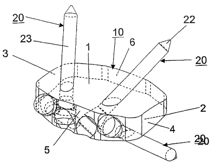
The intervertebral implant of Figs. 1 through 4 consists of a 3D structure 10
exhibiting both a convex top side 1 and a convex underside 2, the two sides
each being
designed to rest against the end plates of two adjacent vertebras. To attain
improved
anchoring, the top side 1 and the underside 2 may be topographically shaped
and be
fitted with grooves, ribs or teeth, or their surfaces may be merely roughened.
The 3D implant structure 10 moreover comprises s left side face 3 and a right
side face 4, also a front face 5 and a rear face 6. The implant structure 10
also may be
hollow and its outer surface may comprise perforations.
The implant structure 10 comprises a plurality of boreholes 9 passing through
it
and receiving longitudinal affixation elements 20. Preferably four such
boreholes 9 shall
be provided.
At least one of the boreholes 9 is designed in a way that the longitudinal
affixation
element 20 received therein may be rigidly connected to the intervertebral
implant. The
boreholes 9 are conical for that purpose.
Preferably the affixation elements 20 are bone screws having a head 21 and a
tip 22. The head 21 conically tapers toward the shank 23, the conicity of the
head 21
corresponding to the conicity of the borehole 9. Moreover the four boreholes 9
may be
fitted with inner threads 11.
As regards the embodiment variation shown in Figs. 5 through 7, the 3D
structure
is fitted at its front face 5 with a preferably metallic insert 8 into which
the affixation
elements 20 may be anchored. The insert 8 is mounted in vertically
displaceable
manner in the 3D structure 10.

Representative Drawing
A single figure which represents the drawing illustrating the invention.
Administrative Status

For a clearer understanding of the status of the application/patent presented on this page, the site Disclaimer , as well as the definitions for Patent , Administrative Status , Maintenance Fee  and Payment History  should be consulted.

Administrative Status

Title Date
Forecasted Issue Date 2010-01-19
(86) PCT Filing Date 2002-02-19
(87) PCT Publication Date 2003-08-28
(85) National Entry 2004-09-02
Examination Requested 2007-02-16
(45) Issued 2010-01-19
Deemed Expired 2018-02-19

Abandonment History

There is no abandonment history.

Payment History

Fee Type Anniversary Year Due Date Amount Paid Paid Date
Reinstatement of rights $200.00 2004-09-02
Application Fee $400.00 2004-09-02
Maintenance Fee - Application - New Act 2 2004-02-19 $100.00 2004-09-02
Maintenance Fee - Application - New Act 3 2005-02-21 $100.00 2005-01-20
Extension of Time $200.00 2005-12-05
Maintenance Fee - Application - New Act 4 2006-02-20 $100.00 2006-01-27
Registration of a document - section 124 $100.00 2006-04-05
Maintenance Fee - Application - New Act 5 2007-02-19 $200.00 2007-02-05
Request for Examination $800.00 2007-02-16
Maintenance Fee - Application - New Act 6 2008-02-19 $200.00 2008-01-14
Maintenance Fee - Application - New Act 7 2009-02-19 $200.00 2009-02-19
Registration of a document - section 124 $100.00 2009-07-15
Final Fee $300.00 2009-11-04
Maintenance Fee - Patent - New Act 8 2010-02-19 $200.00 2010-01-29
Maintenance Fee - Patent - New Act 9 2011-02-21 $200.00 2011-01-24
Maintenance Fee - Patent - New Act 10 2012-02-20 $250.00 2012-01-25
Maintenance Fee - Patent - New Act 11 2013-02-19 $250.00 2013-01-09
Maintenance Fee - Patent - New Act 12 2014-02-19 $250.00 2014-01-08
Maintenance Fee - Patent - New Act 13 2015-02-19 $250.00 2015-01-29
Maintenance Fee - Patent - New Act 14 2016-02-19 $250.00 2016-01-27
Owners on Record

Note: Records showing the ownership history in alphabetical order.

Current Owners on Record
SYNTHES USA, LLC
Past Owners on Record
CAIN, CHRIS M. J.
MATHIEU, CLAUDE
SYNTHES (U.S.A.)
SYNTHES GMBH
Past Owners that do not appear in the "Owners on Record" listing will appear in other documentation within the application.
Documents

To view selected files, please enter reCAPTCHA code :


To view images, click a link in the Document Description column. To download the documents, select one or more checkboxes in the first column and then click the "Download Selected in PDF format (Zip Archive)" or the "Download Selected as Single PDF" button.

List of published and non-published patent-specific documents on the CPD .

If you have any difficulty accessing content, you can call the Client Service Centre at 1-866-997-1936 or send them an e-mail at CIPO Client Service Centre.


Document
Description 
Date
(yyyy-mm-dd) 
Number of pages   Size of Image (KB) 
Abstract 2009-05-20 1 22
Drawings 2004-09-02 3 62
Claims 2004-09-02 6 217
Abstract 2004-09-02 1 22
Representative Drawing 2004-09-02 1 14
Description 2004-09-02 5 253
Cover Page 2004-11-16 1 48
Claims 2007-05-01 4 133
Representative Drawing 2009-12-21 1 12
Cover Page 2009-12-21 2 50
Fees 2009-02-19 1 43
PCT 2004-09-02 13 538
Assignment 2004-09-02 3 89
Correspondence 2004-11-04 1 25
PCT 2004-09-03 5 217
PCT 2004-09-02 1 49
Correspondence 2005-12-05 1 42
Correspondence 2006-01-12 1 15
Assignment 2006-04-05 7 315
Prosecution-Amendment 2007-02-16 1 38
Prosecution-Amendment 2007-05-01 6 169
Assignment 2009-03-13 11 620
Assignment 2009-07-15 3 156
Correspondence 2009-11-04 1 41