Note: Descriptions are shown in the official language in which they were submitted.
CA 02478992 2004-09-13
WO 03/078969 PCT/US03/06630
ABOVEGROUND LEAK DETECTION SYSTEM FOR DETECTING
SUB-SURFACE FLUID LEAKS FROM FLUID CONTAINING VESSELS
Background Of The Invention
The present invention relates generally to leak
detection systems for detecting fluid leaks from fluid
storage tanks using distinctive tracer compounds to provide
detectable components in a fluid leak from the tank. The
present invention also relates to a system for soil gas
sampling, analysis and reporting to determine the presence
and magnitude of a fluid leak from a fluid storage tank.
More particularly, the present invention relates to an
aboveground system that collects sub-surface soil gases for
analysis without the need to penetrate the soil. The present
invention exhibits utility whether used to detect leaks in
underground fluid storage tanks, aboveground fluid storage
tanks or in fluid transfer pipelines. For purposes of
clarity all such vessels shall be referred to as fluid
storage tanks. The fluid stored in the fluid storage tank
may be either a liquid, such as gasoline, or may be a gas,
such as methane, natural gas, butane, propane or the like.
The present invention further provides a tracer leak
detection method that relies upon the addition of a highly
volatile liquid chemical to the fluid contained within the
fluid storage tanks. These tracer chemicals provide a unique
and identifiable analytical signature. This signature is
then used to detect and localize very small leaks from fluid
storage tanks. When a leak occurs in the fluid storage
tank, the leaking fluid will contain a quantity of the
tracer chemical. The tracer escapes from the fluid by
vaporization and disperses into the surrounding soil by
molecular diffusion. Soil gas samples are collected from the
-1-
CA 02478992 2008-02-06
subsurface soil area by withdrawing a volume of soil gas
through the surface of the soil, including any man-made
surfaces thereupon, e. g. , concrete, asphalt, etc. Gas
chromatography is employed on the collected soil gas
samples to reveal the presence of the gas phase tracer,
if any is present in the collected sample. The selection
of tracer is important to insure that it provides a
unique signature for gas chromatography.
The types of tracer chemicals useful in the present
invention are more fully described in U. S. Pat. Nos.
4,725,551 and 4,709,557 issued to Glenn Thompson
(hereinafter the "'551 Patent" and the "'557 Patent",
respectively). Ideally, the selected tracer is normally a
highly volatile organic tracer having a boiling point in
the range of about -72 C. to about 150 C., with the
preferred compounds being of the group known as
fluorocarbons.
A wide variety of different soil gas sampling leak
detection methodologies are known. Common to each of
these methods is the provision of some means for
collecting soil gas samples. For example in each of the
`551 and `557 patents a sampling probe is vertically
disposed in the backfill material surrounding an
underground tank. The sampling probe has a plurality of
apertures to permit soil gases to enter the probe for
subsequent evacuation. It is also well known to employ
carbon adsorbents in the sampling probe to collect
hydrocarbons or tracer chemicals for subsequent
collection by desorbing from the carbon and analysis of
the desorbed gas. Similarly, U.S. Pat. No. 4,754,136
discloses that a neutron backscatter gauge may be lowered
into the sampling probe to determine whether the
2
CA 02478992 2004-09-13
WO 03/078969 PCT/US03/06630
probe contains volatile organic material indicative of a
leak from a fluid storage tank. A positive neutron back
scatter reading is verified by running a gas chromatogram on
a soil gas sample collected from the sampling probe and
comparing the chromatographic signature with the known
material in the fluid storage tank.
Each of these leak detection systems require that a
soil gas sample be taken from the sub-surface sampling probe
then analyzed on a gas chromatograph. Each of these systems
require that some type of probe be inserted into the sub-
surface soil region proximate to the fluid containing tank
in order to sample soil gases for leak detection. None of
these systems, however, provide a method or apparatus for
sampling soil gases for leak detection that does not require
insertion of probes, housings or other devices for
collection of the soil gas samples. Moreover, none of these
conventional systems offer an apparatus and method for
collecting sub-surface soil gas samples from above the
surface of the soil. It has been found desirable, therefore,
to provide an apparatus and method for collecting sub-
surface soil gas samples above ground by evacuating soil
gases from the soil surface, passing the gas sample through
a filter and onto an adsorbing bed specific for adsorbing
distinctive tracer chemicals present in the sub-surface
fluid storage tank.
Summary Of The Invention
Underground and above-ground fluid storage tanks and
fluid pipelines interconnecting such storage tanks with
-3-
CA 02478992 2004-09-13
WO 03/078969 PCT/US03/06630
dispensing pumps typically contain environmentally hazardous
chemicals, such as hydrocarbon fuels or solvents. Some
portion or all of the tank and pipelines often reside in the
sub-surface soil that is covered by a man-made material,
such as concrete or asphalt. Conventional leak detection
systems require sub-soil insertion of a field of probes or
wells that penetrate into the underground area proximate the
pipelines or fluid storage tanks. Soil gas samples are
obtained either by evacuating samples from the probes or
wells or by adsorbing soil gases onto an adsorbent bed
placed within the probe or well and removing the adsorbent
bed from the probe or well for analysis. Where the fluid
storage tanks and/or the pipelines are located in regions
covered by man-made materials, insertion of probes and/or
wells into the sub-surface soil area is difficult, expensive
and labor-intensive.
It is, therefore, a principal object of the present
invention to provide a system for determining whether a
fluid storage tank is leaking without the need to penetrate
into the sub-surface soil area. This objective is achieved
by providing an apparatus which is usable above-ground for
sampling sub-surface soil gas samples for analysis of the
presence of a distinctive chemical tracer present introduced
only into the fluid storage tank. The present invention
comprises an apparatus that includes a sled base consisting
of a planar quadrilinear, or ski shaped plate (hereafter
called the "plate") having an upturned leading edge and
having an annular opening passing through the plate and
centrally positioned on the plate, a tubular manifold in
fluid flow communication with the annular opening and
passing upwardly therefrom, to a sample collection means.
The sample collection means is comprised of a vacuum pump, a
-4-
CA 02478992 2004-09-13
WO 03/078969 PCT/US03/06630
filter, and a sample tube containing an adsorbent material
specific for the distinctive tracer introduced into the
fluid contained within the fluid storage tank. A flow meter,
to enable monitoring the amount of sample that passes
through the adsorbent tube, may be used at the out let of
the sample collection means. A pressure gauge or vacuum
gauge placed between the pump and the adsorbent tube may
also be used to monitor the rate of airflow through the
adsorbent tube.
The sample collection means may be mounted on the
plate, in which case it is connected directly to the opening
in the central portion of the plate. Or, the sample
collection means may be mounted remotely from the plate,
either carried in a backpack or mounted in a vehicle, in
which case the sample collection means is connected to the
opening in the central portion of the plate by means of an
appropriate length of small diameter tubing sufficient to
span the distance from the plate to the sample collection
means. Also, if the sample collection means is mounted
remotely from the plate, it may be connected directly to a
gas chromatographic means for analysis of the chemical
tracer. If the sample collection means is not connected
directly to the gas chromatograph, then the sample tubes are
removed manually from the collection apparatus and manually
connected to the gas chromatograph for analysis.
These and other objects, features and advantages of the
present invention will become more apparent to those skilled
in the art from the following more detailed description of
the preferred embodiments of the invention taken with
reference to the accompanying drawings.
Brief Description Of The Drawings
-5-
CA 02478992 2004-09-13
WO 03/078969 PCT/US03/06630
Fig. 1 is a diagrammatic view of a tank farm including
aboveground and underground fluid storage tanks and fluid
pipelines.
Fig. 2 is a diagrammatic view of the present invention
being drawn by a motor vehicle proximate to an underground
fluid storage tank.
Fig. 3 is a side elevational view of the soil gas
sampling apparatus with the sample collection means mounted
directly on the plate in accordance with the pres.ent
invention.
Fig. 4 is a side elevational view of the soil gas
sampling system of the present invention with the sample gas
collector mounted in a motor vehicle and couple to a gas
chromatograph to provide continuous analytical cycling of
soil gas samples.
Fig. 5 is a flow diagram illustrating the soil gas
sampling method of the present invention.
Fig. 6 is a graph illustrating the results of tracer
measurement from Example 1, below.
Detailed Description Of The Preferred Embodiments
The inventive system for aboveground sampling of sub-
surface soil gases for detection of distinctive chemical
tracer signatures therein is illustrated with reference to
the accompanying drawings. With specific reference to FIG. 1
there is shown an exemplary fluid storage tank farm. An
underground fluid storage tank 12 placed within the sub-
-6-
CA 02478992 2008-02-06
surface region and is supported by an earthen material 4,
such as a backfill of soil, pea gravel or sand. An
aboveground fluid storage tank 13 is constructed onto the
soil and typically placed onto a sand bed. A plurality of
fluid pipelines 17 is disposed either in the subsurface
region or penetrates the surface and resides above the
earthen surface. A fluid 14, such as a gas or liquid, is
contained within the fluid storage tanks and pipelines
12, 13,17 and is dispensed therefrom by pumps 19.
A tracer chemical 16 is introduced into the fluid 14
within fluid storage tanks 12,13 or pipelines l.
Preferred tracer chemicals are described in greater
detail in the aforementioned Thompson `551 and `557
Patents. Ideally, the selected tracer is normally a
highly volatile organic tracer having a boiling point in
the range of about -72 C. to about 150 C., with the
preferred compounds being of the group known as
fluorocarbons.
A fluid leak 18 from the fluid storage tanks 12, 13
or the pipelines 17 into the earthen material 4, causes
the tracer chemical 16 to also leak into the earthen
material 4, volatilize in the subsurface soil and
disperse in a tracer plume 20 within the earthen material
4, thereby providing a unique detectable component in the
earthen material 4.
The inventive soil gas collection apparatus 20 is
depicted generally in Fig. 2, in use, and more
specifically in Fig. 3. Soil gas collection apparatus 20
consists generally of a planar base member 22 having an
upper surface and a lower surface and at least one
aperture 24 passing through the planar base member 22 and
communicating between the upper and lower surfaces
thereof. The planar base
7
CA 02478992 2004-09-13
WO 03/078969 PCT/US03/06630
member 22 is preferably fabricated of a highly durable
material, such as steel, carbon fiber materials or plastics.
It is preferable that the planar base member be configured
to have a sled-like geometry with an upturned leading edge
that permits the base member 22 to more readily traverse
uneven surfaces. A protective cover may also be added to
prevent brush or other material from catching or settling on
the pump, tubing or other mechanisms on the planar base
member when the apparatus 20 is being drawn through
vegetated areas. A tether (not shown) is preferably attached
to a leading section of the planar base member 22 so that
the apparatus 20 may be moved by attachment to a motor
vehicle 21 or by a human being.
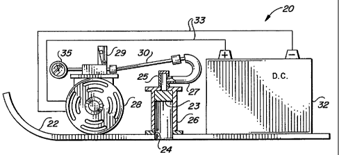
At least one intake manifold 26 is connected in fluid
flow communication with the at least one aperture 24 and is
upstanding from the upper surface of the planar base member
22. The at least one intake manifold 26 may be connected to
the planar base member by suitable means, such as threaded
couplings, interference couplings or welding, or it may be
formed as an integral monolithic component with the planar
base member such as by casting or stamping. A pump 28 is
mounted on the upper surface of the planar base member 22
and is connected in fluid flow communication with the at
least one intake manifold 26 by tubing 27. A filter medium
23 is preferably disposed within the at least one intake
manifold 26 or in-line with the fluid flow through the at
least one intake manifold 26 to filter particulates from the
fluid flow. Interposed in-line between the at least one
intake manifold 26 and the pump 28 is at least one sample
tube 30 containing an adsorbent material specific for at
least one of the distinctive chemical tracer compounds
introduced into the fluid storage tanks 12, 13 or the
-8-
CA 02478992 2004-09-13
WO 03/078969 PCT/US03/06630
pipelines 17. Sample tube 30 is removable and connectable
to a gas chromatograph (not shown) for purposes of desorbing
any adsorbed tracer compounds for quantification and
analysis. Tubing 27 is connected at one end thereof, to a
connector 25 mounted on the at least one intake manifold 26,
and at a second end to the sample tube 30. Sample tube 30
is connected at a second end thereof to the pump 28. Pump
28 is driven by a power source 32 that supplies electrical
power to the pump via electrical connectors 33. A flowmeter
29 is also preferably provided on the exhaust side of the
sample tube 30 to monitor the fluid flow through the sample
tube 30 and ensure that sufficient volumes of fluid flow are
being sampled.
In accordance with the present invention, the pump 28,
at least one intake manifold 26, connector 25, tubing 27,
sample tube 30 and power supply 32 are all mounted onto the
planar base member 22. Those skilled in the art will
understand and appreciate, however, that the power supply
32, the pump 28 and even the at least one sample tube 30 may
be carried on a structure separate from the planar base
member 22, while still being in fluid flow communication and
electrical communication therewith.
In use, the soil collection apparatus 20 may be
attached to a motor vehicle 21 or drawn by a human being
(not shown) and drawn across the surface of the subsurface
region field to be tested. The surface 5 of the subsurface
region field may be a earthen surface or may be covered by a
porous man-made material 7, such as concrete or asphalt.
Porous man-made materials permit permeation and diffusion of
the chemical tracer compounds into and through the man-made
materials and permit detection of the chemical tracer
compounds therethrough.
-9-
CA 02478992 2004-09-13
WO 03/078969 PCT/US03/06630
Soil gas samples are typically analyzed by gas
chromatography. Using gas chromatography it is possible to
analyze whether the distinctive chemical tracer compound is
present in the soil gas sample, and, if so, its
concentration level in the sample.
Fig. 4 illustrates an alternative embodiment of the
invention 70 in which the planar base member 22 is mounted
with at least one intake manifold 26 in fluid flow
communication though an opening in the planar base member
(not shown) substantially as described above. In accordance
with this alternative embodiment of the invention 70,
however, the pump 28 and power supply 32, and the electrical
connectors 33 are remotely situated from the planar base
member 22, such as being mounted on a vehicle 21. The
planar base member 22 is tethered via a line 71 secured to
the vehicle 21. A fluid conduit 72 communicates between the
pump 28 and the at least one intake manifold 26 extends
between the vehicle and is preferably also coupled to the
line 71. In this configuration, the pump will evacuate a
subsurface soil gas sample from the at least one intake
manifold 26, withdraw the sample thorough the pump, and feed
the sample either directly to a gas chromatograph 76 or may
be adsorbed on a sampling tube (not shown) and desorbed for
feeding into the gas chromatograph 76. This alternative
embodiment 70 permits a continuous cycling of subsurface
soil gas samples through the analytical instrument to
provide a more "real-time" reading on the tracer levels in
the subsurface soil samples.
Fig. 5 illustrates the method 40 for detecting the
presence of a distinctive chemical tracer compound, and
thus, of a leak in one or more fluid storage tanks or
pipelines in accordance with the present invention. First,
-10-
CA 02478992 2004-09-13
WO 03/078969 PCT/US03/06630
a soil gas collector, such as described above, is passed
over the sampling region in proximity to the storage tanks
and pipelines to be tested 42. The soil gas collector is
supported by and rests upon the surface of the sampling
region, which may consist of earthen material, gravel,
concrete, asphalt, sand, or other similar porous material.
While the soil gas collector is being passed over the
sampling region, soil gas samples are evacuated 44 from the
sampling region by drawing the soil gas samples through the
surface of the sampling region and into the soil gas
collector. The soil gas samples pass through an intake
manifold on the soil gas collector 46 and are captured 48 in
a sampling tube. Any tracer compound is adsorbed 50 onto an
adsorbent material within the sampling tube, and non-
adsorbed soil gas is exhausted 56 from the soil gas
collector. After completing a sampling run in the sampling
region, the sampling tube is disengaged from the soil gas
collector and connected to a gas chromatograph where any
captured chemical tracer compound is desorbed 52 from the
adsorbent material. The desorbed sample is then fed into a
gas chromatograph for analysis 54 of the presence and
concentration of any distinctive chemical tracer in the
sample. If the distinctive chemical tracer is found in the
sample, the sample may be correlated to the geographical
coordinates of the sample origin and the concentration of
the chemical tracer mathematically correlated to quantify a
leak rate, based upon concentration in sample volume and
known concentration of tracer in known volume of fluid in
the storage tank or pipeline.
Example 1
A leak test was performed on a 4-mile section of
underground pipeline that was believed to be leaking because
-11-
CA 02478992 2004-09-13
WO 03/078969 PCT/US03/06630
it had failed a hydrostatic pressure test. The leak was
very small and other leak testing methods had failed to
locate the leak. The fluid in the pipeline was inoculated
with 10 ppb of a first fluorocarbon tracer, Tracer R. A
second fluorocarbon tracer, Tracer E, that was distinct
from the tracer contained within the pipeline was used as a
leak simulation. The Tracer E was released into the soil
outside of the pipeline as a means of verifying the
performance of the leak detection procedure and as a means
of calibration to determine the size of any leaks that were
detected. The amount of Tracer E released into the soil was
equivalent to the amount of Tracer R that was contained in
10 gallons of fluid from inside the pipeline.
The inventive soil gas collection sled was dragged
behind a truck for 4 miles of pipeline over the course of
about 5 hours while continuously evacuating soil gas samples
from underneath the sled. The sample collection tubes were
changed every 260 feet (approximately every 79 meters). A
total of 82 samples were collected. The samples were
analyzed using gas chromatography and the presence of the
tracer from both the pipeline leak and from the simulated
leak were verified. The results of the tracer measurements
are shown in Figure 6. By comparing the amount of Tracer R
detected from the actual leak with the amount of Tracer E
detected from the 10 gallon simulated leak, it can be seen
that the real leak was only slightly larger. The real leak
appears to have been only 12 or 15 gallons by comparison.
From the foregoing, those skilled in the art will
understand that the invention has been fully and fairly
described in such a manner as to enable one skilled in the
art to practice the invention. While the best mode for
practicing the invention has been disclosed, those in the
-12-
CA 02478992 2004-09-13
WO 03/078969 PCT/US03/06630
art will understand and appreciate that a wide variety of
variations and substitutions may be made in, for example,
individual valve and switch selections, connection line
materials, tracer selection, tank or pipeline type and
operational parameters without departing from the spirit and
scope of the present invention.
-13-