Note: Descriptions are shown in the official language in which they were submitted.
CA 02479303 2004-09-15
WO 03/081311 PCT/US03/03337
DEVICE FOR ALIGNING FIBER OPTIC CONNECTORS
Technical Field
The present invention pertains to a device useful in an optical connector
containing
mufti-fiber ferrule containing optic fibers. In particular, the inventive
device is an
alignment element that fits into a housing such that when a connector is
slidably attached
to the housing, the alignment element forces the connector against a reference
surface
thereby ensuring proper alignment of the connectors.
Background
The use of optical fibers for high-volume, high-speed communication is well
established. As the volume of transmitted information grows, the use of
optical fiber
cables that have multiple optical fibers and of systems using multiple optical
fiber cables
has increased.
1 S Fiber optic terminations are evolving from single terminations to mass
terminations. Within the past few years, ribbonized mufti-fiber cables have
been
developed. In conjunction with these cable development efforts, mufti-fiber
mounting
ferrules also have been developed.
The design of traditional electronic cabinets is now being altered to
accommodate
optical and opto-electronic devices. In traditional cabinet designs, the
cabinet contains a
box having a backplane and plurality of internal slots or racks, generally
parallel to each
other. Components are mounted on planar substrates, commonly referred to as
"circuit
boards" or "daughter cards," which are designed to slide into the slots or
racks within the
cabinet.
An example of a backplane application is the interconnection of telephone
switching equipment where the cards, having optical and electronic
telecommunication
components, typically disposed on daughter cards, are slid into cabinets. As
with
electrical cables, the need exists to provide for a means to allow the fiber
signals to pass
through the backplane of the cabinets. Another need is to have a removable
fiber
termination from the front side and the backside of the backplane.
Furthermore, when the
cards are inserted and removed from a rack coupled to the backplane, coupling
and
1
CA 02479303 2004-09-15
WO 03/081311 PCT/US03/03337
uncoupling of the optical connections in the card occurs in a blind mating
manner causing
added alignment challenges.
In order to maintain appropriate transmission of light signals, optical fiber
ends are
to be carefully aligned along three movement (x, y, and z in Cartesian
coordinate system)
axes, as well as angularly. As the number of optical fibers to be aligned
increases,
alignment challenges also increase. Blind mating of a card-mounted component
to a
backplane connector has been found to create special alignment challenges
along the axis
of interconnection.
For the purposes of the present description, the axis of interconnection is
called the
longitudinal or x-axis and is defined by the longitudinal alignment of the
optical fibers at
the point of connection. Generally, in backplane applications, the
longitudinal axis is
collinear with the axis of movement of the cards and the axis of connection of
the optical
fibers in and out of the cabinets. The lateral or y-axis is defined by the
perpendicular to
the x-axis and the planar surface of the card. Finally, the transverse or z-
axis is defined by
the orthogonal to the x-axis and the backplane surface. The angular alignment
is defined
as the angular orientation of the card with respect to the x-axis.
Some skilled in the art have tried to address the ferrule alignment issue. For
example, US Patent No. 5,619,604 (Shiflett et al.) discloses a mufti-fiber
optical connector
using a mufti-fiber ferrule such as a mechanical transfer (MT) connector that
can be mated
with and received by an optical receptacle. Multiple alignment features help
align and
mate the connector to another mufti-fiber object. The connector has a guide
prong beneath
which is mounted the ferrule. The prong provides a reference surface that
functions as a
pre-alignment mechanism for the ferrule. The connector also has a U-shaped
enclosure
containing a spring tab. In use, the reference surface engages the upper
surface of the
ferrule while the spring tab engages the lower surface of the ferrule and
forces it against
the reference surface.
The need remains for other connector systems that provide a repeatable and
cost
effective way to mate ferrules.
Summary
One of the challenges in a mechanical system, such as the present mufti-fiber
connector system, stems from the fact that most of the components are
precision molded
and machined. As such, the dimensions of the components consistently need to
be as near
2
CA 02479303 2004-09-15
WO 03/081311 PCT/US03/03337
to the design specification as possible for repeated alignment of the
components. Holding
the components to precise target dimensions (i.e., dimensions that can deviate
from one
another only in the 0.001 inch range (0.254 mm)) can be difficult and very
expensive for
molded and machined parts. Even if the components are consistently held to the
target
dimensions when fabricated, in use the components may be exposed to
environmental
conditions that may slightly change their dimensions. Most of the components
can be
used in applications lasting up to twenty years, further increasing the
possibility of
dimensional changes. The present invention provides for a cost effective
approach to
align the components that may have slight dimensional deviations, caused in
the
manufacturing process, caused by environmental changes, caused by extended
use, or
caused by a combination of these and other factors.
The present invention relates to an optical fiber interconnect system that
provides
alignment of the ferrules in the x, y, and z directions by use of a unique
alignment
element. In some embodiments, the inventive interconnect system provides for
interconnecting arrays of optical fiber cables in an individual or in a
collective fashion. As
used herein, the term "backplane" refers to an interconnection plane where a
multiplicity
of interconnections may be made, such as with a common bus or other external
devices.
In very brief summary, the present invention provides for an alignment element
exhibiting spring-like behavior where the alignment element provides a
deflection force
against ferrule housings to align the ferrules residing therein. In one
preferred
embodiment, the present invention provides for a multi-fiber optic connector
system
comprising: (a) a first housing assembly comprising a first portion having at
least one first
cavity, a second portion having at least one second cavity, each second cavity
having a
reference surface and a first groove and wherein the first and second portions
are aligned
such that the first cavity and the second cavity form a passageway, at least
one alignment
element disposed on the first groove of the second portion; and (b) at least
one first optical
connector comprising a first ferrule having a plurality of ports, the first
ferrule disposed
inside a ferrule housing. When the first optical connector is inserted into
the first portion
and resides in the passageway, the alignment element contacts the first
ferrule housing and
forces it against the reference surface.
In the present invention, ferrule alignment can be achieved in various ways.
For
example, the first and second cavities, the ferrule housing, and the
protrusions, by virtue of
3
CA 02479303 2004-09-15
WO 03/081311 PCT/US03/03337
their size and shape, form the coarse alignment. Because, as discussed above,
the
dimensions of these components can vary, the fine alignment is achieved by use
of the
alignment element.
Unlike US Patent No. 5,619,604, the present invention does not use a tab to
push
the ferrule directly against a reference surface. Instead, the present
invention uses a
unique alignment element to guide a ferrule housing and/or a protrusion
against a
reference surface. One of the advantages of the present invention is that, by
virtue of the
design, the ferrules are protected inside a housing and are allowed to float
inside the
housing. The term "float" as used in the previous sentence means generally
that the
ferrules have some freedom of movement in the y and z directions so that as
the ferrules
are being mated during interconnection or as the ferrules are exposed to
various
environmental conditions, the probability of having the ferrules mate or stay
mated,
respectively, is increased.
Brief Descr~tion of the Drawings
The invention will be further described with reference to the drawing wherein:
Figure 1 is an exploded isometric view of one embodiment of a connector system
in accordance with the present invention;
Figure 2 is an exploded side view of an illustrative alignment element 300 and
of a
second portion 120 of a backplane housing;
Figure 3 is an assembled view of an illustrative connector;
Figure 4 is an alternative embodiment of an alignment element 300 that can be
used accordance with the present invention; and
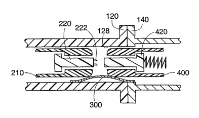
Figure 5 is a cross-sectional schematic view of one aspect of the invention.
These figures are idealized, not drawn to scale, and are intended merely to be
illustrative and non-limiting.
Detailed Description
Figure 1 illustrates one embodiment of an optical interconnect system 10 in
accordance with the present invention.
The optical interconnect system 10 includes a first housing 100 (also referred
to as
a "backplane housing"). In use, the backplane housing is mounted on a
backplane (not
4
CA 02479303 2004-09-15
WO 03/081311 PCT/US03/03337
shown). In the present embodiment, backplane housing 100 comprises molded
plastic
pieces of a dielectric material that have the structural strength and
dimensional stability
required to maintain control of the optical fiber's position. Such materials
include, but are
not limited to, thermoplastic injection moldable polymers that are filled or
unfilled with
reinforcement agents, and transfer moldable polymers such as epoxy. The
backplane
housing 100 includes a first portion 140, a second portion 120, at least one
alignment
element 300, and optionally first doors 180 and second doors 160.
First portion 100 has at least one first cavity 142 for receiving a first
optical
connector 400, a first surface 146 where first doors 180 can be mounted, and
bores 152 as
a means for attaching the second portion to the first portion and, if desired,
for attaching to
a backplane (not shown). In a preferred embodiment, first portion 100 contains
an array of
four first cavities. In use, as first connector 400 is slidably engaged into
first cavity 142,
first doors 180 fold down and remain in the folded position. In a preferred
embodiment,
the doors are hingedly coupled to first surface 146 and close a pair of first
cavities.
Second portion 120 has at least one second cavity 122, each cavity having:
reference surface 128, first groove 130 for capturing and holding alignment
element 300 in
place and second groove 132 for polarization of optical connector 400. The
second
portion also has first surface 126 and second surface 124. As better shown in
Figure 2,
groove 130 starts from first surface 126 and extends into the second cavity.
In a preferred
embodiment, second portion 120 contains an array of four-second cavities.
Optionally, the
second portion can include male locating features 125 that engage with
corresponding
female features (not shown) on second surface 144 of first portion 140. The
locating
features help ensure accurate alignment between the first and second portions
during
assembly.
It should be understood that, in alternative embodiments, portions 120 and 140
do
not need to be separate and could be molded as one piece. Splitting off
portions 120 and
140, however, may allow for more freedom in mold core design.
In the present embodiment, fasteners 150 secure the backplane housing 100 to a
backplane (not shown). Fasteners 150 include threaded metal inserts inserted
through
matching bores 152 in the first and second portion 140 and 120 of the
backplane housing
100. Those skilled in the art will readily appreciate that mounting screws are
used in
conjunction with fasteners 150 and that a variety of fastening mechanisms,
adhesives,
5
CA 02479303 2004-09-15
WO 03/081311 PCT/US03/03337
interference fitting, and other devices known in the art may be used to align
and secure
backplane housing 100.
Doors (also referred to as "shutters") 160 and 180 are preferably retractable.
The
doors in the present embodiment include flat spring metal members hingedly
coupled to
first surface 146 and second surface 124. As stated above, the doors are
designed to fold
down when an object, such as, e.g, a connector, is inserted into the cavities.
The doors can
be made of a conductive metal material, such as tempered stainless steel,
beryllium/copper
alloys or other materials, and are coupled to provide a grounding electrical
path. The
doors can serve several functions, such as (1) providing a physical barner to
limit ambient
contamination from entering the assembled connector housing, (2) absorbing and
route to
ground electric magnetic interference that may otherwise leak through the
cavities through
the backplane; and (3) providing eye safety from emitted light signals from
either end of
the backplane.
The double door design allows for the sealing of the optical connection
without the
need to include special gated terminations at each connector. The double door
arrangement also allows for at least one door to be closed any time a
receiving cavity is
not filled by both a rear and a front plug. In embodiments where the user is
not concerned
with any of the above issues, the use of doors may be optional without
effecting the
performance and function of the backplane housing.
As better shown in Figure 2, alignment element 300 has two major surfaces 301a
and 301b that are substantially parallel to one another, at least one tab 302
extending from
at least one of the two major surfaces, a curved portion 308, a first foot
portion 304, and a
second foot portion 306. For ease of understanding, only one alignment element
is shown.
Each foot portion has a flat surface extending from the foot thereby allowing
for
movement of each foot when the alignment element is in use. In a preferred
embodiment,
alignment element 300 fits into first groove 130 such that tab 302 having a
width w reside
in the groove. Groove 130 is preferably designed so as to incorporate the
curved shape of
the alignment element. Even though the alignment element of Figure 2 has
curvature, its
dimensions, in an unused state can be described as having a length in the
range of about
0.5 to 0.75 inches (12.7 to 19.1 mm), a width of in the range of about 0.4 to
0.6 inches
(10.2 to 15.2 mm), and a thickness that is dependent on the material selected
and the
amount of force desired. In a preferred embodiment, the alignment element has
a
6
CA 02479303 2004-09-15
WO 03/081311 PCT/US03/03337
thickness of about 0.003 to 0.015 inch (0.18 to 0.38 mm), more preferably
about 0.004 to
0.006 inch (0.10 to 0.15 mm).
The alignment element has spring-like properties and can be made from metals,
plastics, and combinations thereof. Preferably, the alignment element is a
metal selected
from the group consisting of beryllium copper alloy, stainless steel, and
phosphor bronze.
In use, when an object (such as a connector) is disposed on the alignment
element, it
deflects from about 0.005 to 0.015 inch (0.13 to 0.38 millimeters) and the two
feet 304 and
306 are displaced from their original position. The foot portions provide an
advantage in
that, because they have a flat portion, the alignment element does not lodge
itself into the
housing.
Figure 4 shows an alternative embodiment of alignment element 300. In this
embodiment, the alignment element is self attaching to floor 138 of second
portion 120.
Also, when the self attaching aligrunent element is used, the second portion
may need to
be modified, e.g, grooves 130 may not be needed.
The alignment elements of Figures 2 and 4 can be made by various methods,
depending on the materials used. If a metal-based material is used, the
alignment element
can be fabricated by metal stamping. If a polymer-based material is used, the
alignment
element can be fabricated by injection molding. One skilled in the art will
readily
appreciate that a variety of fabrication methods can be used to fabricate the
alignment
element.
As shown in Figure 1, a second housing 200 (also referred to as "daughter card
housing") includes at least one hollow protrusion 210 shaped in size to
correspond and fit
into rear cavities 122 of the backplane housing 100. In use, the daughter card
housing is
mounted on a substantially planar card, such as a circuit card or a daughter
card. The card
may include optical, optoelectronic, and electronic components. Those skilled
in the art
will be readily aware of the various methods for attaching the daughter card
housing 200
to the card. Alternative embodiments may include attachment means such as
mechanical
fasteners, spring clips or the like.
The protrusions 210 in the present embodiment are hollow and rectangular
shaped
and are terminated in a truncated pyramid shaped lead 212. The pyramid shaped
lead
functions as a pre-alignment and allows for compensation of certain mating
misalignments
by directing protrusions 210 into second cavities 122 of the backplane
housing.
7
CA 02479303 2004-09-15
WO 03/081311 PCT/US03/03337
Protrusions 210 are shaped to provide alignment with respect to the inside
walls of second
cavities 122. Protrusions 210 also provide an automatic pressure for opening
front doors
160 during mating. The inner walls of protrusion 210 define a stepped cavity
214 that
provides guidance to a fiber optic ferrule 220 to be seated inside of the
stepped cavity. In
the present embodiment, the stepped cavity 212, is shaped to receive an
industry standard
ferrule, such as the mechanical (MT) style optical ferrules.
Figure 3 shows an optical connector 400 having a ferrule 420 seated inside a
ferrule housing 410, holes 422, and a polarization feature 421. Current
connector
assemblies include forward biased spring mounted ferrules. The bias springs
absorb a
limited amount of over travel of the ferrules during mating and provide a
predetermined
spring biasing force thus urging the ferrules intimately together when the
ferrules are in
their mated position.
Figure 5 schematically illustrates a connector system in use and is a
simplified
version of Figure 1. Refernng to Figures 1 and 5, first portion 140 has been
mated with
second portion 120 to form a passageway. Alignment element 300 is disposed
primarily
in the second portion 120 but a portion of it resides in first portion 140.
First optical
connector 400 is slidably engaged into the first cavity and travels into the
second cavity
whereupon it contacts alignment element 300 at which point the element 300
forces the
connector up against reference surface 128. Through openings 124, daughter
card housing
200 is then slidably engaged into the second portion 120 of backplane housing
100.
During this engagement process, second doors 160 are folded down and the
housing 200
stops when second ferrule 220 is mated with first ferrule 420 such that pins
222 reside in
holes 422. By the design of protrusion 210 and second cavity 122, the
protrusion is forced
against the same reference surface 128. By this action, the ferrules 220 and
420 are
aligned. In one embodiment, protrusion 210 does not contact the alignment
element. In
an alternative embodiment, the protrusion 210 does contact the alignment
element.
Another fiber optic connector that can be used in the present invention is
described
in publication WO 01/40839. Figure 2 of the above cited application shows a
cross
section of a backplane with a backplane housing and a daughter card with a
daughter card
housing. The backplane and daughter card housings of the present invention can
be
similarly mounted onto the backplane and the daughter card shown in Figure 2
of the
application.
8