Language selection

Search

Patent 2479785 Summary

Third-party information liability

Some of the information on this Web page has been provided by external sources. The Government of Canada is not responsible for the accuracy, reliability or currency of the information supplied by external sources. Users wishing to rely upon this information should consult directly with the source of the information. Content provided by external sources is not subject to official languages, privacy and accessibility requirements.

Claims and Abstract availability

Any discrepancies in the text and image of the Claims and Abstract are due to differing posting times. Text of the Claims and Abstract are posted:

  • At the time the application is open to public inspection;
  • At the time of issue of the patent (grant).
(12) Patent Application: (11) CA 2479785
(54) English Title: MULTI-PICTURE FRAME APPARATUS AND KIT
(54) French Title: NECESSAIRE PERMETTANT LE MONTAGE DE PLUSIEURS CADRES
Status: Deemed Abandoned and Beyond the Period of Reinstatement - Pending Response to Notice of Disregarded Communication
Bibliographic Data
Abstracts

English Abstract


A modular picture frame apparatus and kit incorporates a plurality of picture
frames of differing
sizes mounted on linear support members. Each picture frame has channels
corresponding to the
horizontal cross-section of the linear support members. Magnets or other
attachment means are
disposed in the channels or on the linear support members to hold the picture
frames in a desired
position on the linear support members. Linear support members may be mounted
on a wall or
other mounting surface. Other elements of the apparatus may include corkboard,
whiteboard,
chalkboard or mirror attached to the mounting surface.


Claims

Note: Claims are shown in the official language in which they were submitted.

-6-
Claims
What is claimed is:
1. A multi-picture frame apparatus comprising:
one or more frame support tracks,
mounting means for mounting the frame support tracks on a support surface,
a plurality of picture frames each having a front and back surface, wherein
each frame
has one medial channel extending the length and one medial channel extending
the width of its
back surface for cooperation with the frame support tracks; and
magnetic bonding means for supporting the picture frames channels on the frame
support
track.
2. The multi-picture frame apparatus of claim 1 further comprising a plurality
of spacer
blocks each having a front and back surface, each spacer block having one
medial channel
extending the length and one medial channel extending the width of its back
surface for
cooperation with the frame support track, and magnetic bonding means for
supporting the spacer
block channels on the frame support tracks.
3. The multi-picture frame apparatus of claim 1 or 2 wherein the magnetic
bonding means
comprises one or more magnets attached to the frame support tracks.
4. The multi-picture frame apparatus of claim 1 or 2 wherein the magnetic
bonding means
comprises one or more magnets attached to each of the channels.
5. The multi-picture frame apparatus of claim 1 further comprising a backing
support for
mounting thereon of the frame support track.
6. The multi-picture frame apparatus of claim 1 further comprising one or more
of a mirror,
a corkboard, a chalkboard and a whiteboard mounted on the visible surface of
the backing
support.

-7-
7. The multi-picture frame apparatus of claim 1 wherein the frame support
tracks and the
channels have a rectangular cross section.
8. A multi-picture frame kit comprising modular frame support track elements,
a plurality of
picture frames having one medial channel extending the length and one medial
channel
extending the width of its back surface for cooperation with the frame support
track, a collapsible
backing support, and mounting means for mounting the kit on a support surface.
9. The multi-picture framing kit of claim 8, further comprising one or more of
a mirror, a
corkboard, a chalkboard and a whiteboard for mounting on the visible surface
of the backing
support.

Description

Note: Descriptions are shown in the official language in which they were submitted.


CA 02479785 2004-08-26
Title of The Invention
MULTI-PICTURE FRAME APPARATUS AlelD I~IT
Technical Field of the Inventiion
The present invention relates generally to picture frames, and more
particularly to an apparatus
and a kit for mounting multiple pictures for display.
Background of the Invention
With the access to low cost photography by consumers, a market has developed
for photography
accessories. tin important segment of this market is picture mounting and
framing.
A wide variety of frames are available in a variety of materials, sizes and
configurations. It is
desirable for a picture frame to be easy to assemble and disassemble, and to
offer a variety of
configurations to permit individual expression in displaying photographs.
It is known to provide a device for mounting and framing a photograph using
magnets to hold a
photograph between front and back surfaces of a frame. Such a device is
described in U.S.
Patent No. 3,885,336 to Olsen.
It is also known to provide an apparatus which comprises a plurality of
separately framed
compartments, each of which may display a photograph mounted thereon by
magnetic means.
Such a device is taught in U.S. Patent No. 5,269,083 to Vampatella.
There are a number of desirable objectives in relation to a mu.lti-picture
frame apparatus. Such
an apparatus should ideally be easy to assemble and disassemble, permit
assembly into a variety
of structures, and allow for easy mounting and dismounting of ~~ictures on the
display surface.
Existing picture framing devices achieve some of these objectives, but with
varying degrees of
success. Many of the prior art devices, such as the Vampatella apparatus, are
bulky and do not
permit of ease of packing and shipping. Prior art devices which are not
modular are not ideal as
they require higher packing, storing and shipping costs.
srb15rb02092

CA 02479785 2004-08-26
-2-
Summary of the Invention
In one of its aspects, the mufti-picture frame apparatus according to the
invention comprises one
or more frame support tracks, mounting means for mounting the frame support
tracks on a
support surface, a plurality of picture frames each having a front and back
surface, wherein each
frame has one medial channel extending the length and one medial channel
extending the width
of its back surface for cooperation with the frame support tracks, and
magnetic bonding means
for supporting the picture frames channels on the frame support track.
The mufti-picture frame apparatus may further comprise a plurality of spacer
blocks each having
a front and back surface, each spacer block having one media:t channel
extending the length and
one medial channel extending the width of its back surface for cooperation
with the frame
support track, and magnetic bonding means for supporting the spacer block
channels on the
frame support tracks. The magnetic bonding means may comprise one or more
magnets attached
to the frame support tracks or to each of the channels.
The mufti-picture frame apparatus may further comprise a backing support for
mounting thereon
of the frame support track.
The mufti-picture frame apparatus may further comprise one or more of a
mirror, a corkboard, a
chalkboard and a whiteboard mounted on the visible surface c~f the backing
support. The frame
support tracks and the channels may have a rectangular cross section.
In another of its aspects, the invention comprises a mufti-picture frame kit
having modular frame
support track elements, a plurality of picture frames having one medial
channel extending the
length and one medial channel extending the width of its back surface for
cooperation with the
frame support track, a collapsible backing support, and mounting means for
mounting the kit on
a support surface.
The mufti-picture framing kit may further comprise one or amore of a mirror, a
corkboard, a
chalkboard and a whiteboard for mounting on the visible surface of the backing
support.
Other aspects of the invention will be appreciated by reference to the
description of the preferred
embodiment which follows and to the claims.
srb\srb02092

' CA 02479785 2004-08-26
-3-
Brief Description of the Drawings
The invention will be described by reference to the preferred embodiment and
the
drawings thereof in which:
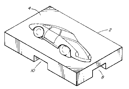
Figure 1 is a perspective view of the front side of a picture frame element,
according to
the invention;
Figure 2 is a perspective view of the rear side of a picture frame element,
according to the
invention;
Figure 3 is a front view of one embodiment of the assembly, according to the
invention;
Figure 4 is a cross-section through line 4-4 of Figure 3 showing a picture
frame element
mounted on a linear support member; and
Figure 5 is a front view of another embodiment of the assembly according to
the
invention.
Detailed Description of Best Mode and
Preferred Embodiment of the Invention
The picture frame assembly and kit of the invention comprises modular
elements. One of the
elements, as shown in Figs. 1 and 2, is a picture frame 2. The; picture frame
is generally planar,
and preferably rectangular in shape, although a variety of shapes is possible.
As best seen in Fig.
l, each picture frame element 2 has a picture mounting surface 4 on its front
surface. As best
seen in Fig. 2, on the opposed rear surface 6, a first linear channel 8
extends the length of the
frame at a medial position and a second linear channel 10 extends the width of
the frame at a
medial position intersecting the first linear channel. One or more magnetic
attraction means 12
are disposed in the linear channels.
Each frame may display on its front surface a photograph or other image, text,
or other items.
The frame elements may be a wide variety of sizes to accommodate photographs
of differing
size.
srb\srb02092

CA 02479785 2004-08-26
-4-
As shown in Fig. 3, the apparatus and kit also comprises at least one linear
support member 14.
The linear support member 14 is of a width and thickness which corresponds to
the width and
depth of the linear channels 8, 10 to permit a close fit behveen the support
member and the
channel. Magnetic attraction means (not shown) are positioned at the interface
between the
S linear support and the channel. Magnetic attraction means may comprise a
magnet on the
surface of the linear support member in cooperation with a magnetic substance,
such as a
magnetic metal in the linear channel. Alternatively, the magnet may be located
in the channel
and the magnetic substance on the linear support member, or magnets of
opposite poles may be
located in the channel and on the linear support member.
The linear support member may be rigid or flexible. A flexible linear support
member may be
bent to a desired shape prior to mounting on a support surface to permit a
wide variety of display
options. Individual picture frames may be easily added to, repositioned on, or
removed from the
mounted linear support member.
As demonstrated in Fig. 4, the corresponding geometry of the linear support
member 14 and the
linear channel 8 provides support to hold the picture frame in a desired
position. The magnetic
attraction means, for example a magnet 18 on the linear support member and a
magnetic
substance 20 in the linear channel, provides additional force to hold the
picture frame in position,
while permitting easy manual removal or repositioning.
Figure S shows another embodiment of the apparatus and kit of the invention.
Linear support
members 14 are mounted on a backing support 22. Individual frame elements 2
may be mounted
on the linear support members in desired positions. Corkboard 24 or other
planar accessories
such as chalkboard, whiteboard or mirror, may be mounted on the backing
support 22. Such
accessories may be provided with an adhesive backing layer i:or mounting the
accessory on the
backing support. The backing support may be mounted on a mounting surface such
as a wall.
Alternatively, with the addition of a stand, the apparatus may be displayed on
a desk or other
horizontal surface.
By completely covering the linear support member in an apparatus such as the
embodiment
shown in Fig. 5, the frames will be better retained in position on the linear
support member. As a
variety of sizes of frames may be used in a desired assembly, the apparatus
and kit may also
include filler pieces (not shown) which are of dimensions selected to
complement the frame sizes
srb\srb02092

CA 02479785 2004-08-26
-$-
for a particular kit, such that the entire linear support member may be
covered by a combination
of frames and filler pieces.
Although in the preferred embodiment magnets are used to hold the frames in
position on the
linear support member, other attachment means are possible.
The modular elements of the picture frame apparatus may be easily disassembled
into a kit for
packing, storing and shipping. The picture frame elements are individually
removable. The
linear support members may be segmented for ease of packing. The backing
support and
accessory materials such as whiteboard, corkboard, blackboaa-d or mirror may
be collapsible by
folding or rolling to permit easier packing, storage and shipping of the kit.
It will be appreciated by those skilled in the art that other variations of
the preferred embodiment
may also be practised without departing from the scope of the invention.
srb\srb02092

Representative Drawing
A single figure which represents the drawing illustrating the invention.
Administrative Status

2024-08-01:As part of the Next Generation Patents (NGP) transition, the Canadian Patents Database (CPD) now contains a more detailed Event History, which replicates the Event Log of our new back-office solution.

Please note that "Inactive:" events refers to events no longer in use in our new back-office solution.

For a clearer understanding of the status of the application/patent presented on this page, the site Disclaimer , as well as the definitions for Patent , Event History , Maintenance Fee  and Payment History  should be consulted.

Event History

Description Date
Application Not Reinstated by Deadline 2010-03-30
Inactive: Dead - No reply to s.30(2) Rules requisition 2010-03-30
Deemed Abandoned - Failure to Respond to Maintenance Fee Notice 2009-08-26
Inactive: Abandoned - No reply to s.30(2) Rules requisition 2009-03-30
Inactive: S.30(2) Rules - Examiner requisition 2008-09-30
Letter Sent 2007-07-09
Inactive: Office letter 2007-07-06
Revocation of Agent Requirements Determined Compliant 2007-07-06
Appointment of Agent Requirements Determined Compliant 2007-07-06
Inactive: Office letter 2007-07-06
Appointment of Agent Request 2007-06-29
Revocation of Agent Request 2007-06-29
Request for Examination Received 2007-06-29
All Requirements for Examination Determined Compliant 2007-06-29
Request for Examination Requirements Determined Compliant 2007-06-29
Inactive: Office letter 2006-09-11
Revocation of Agent Requirements Determined Compliant 2006-09-11
Appointment of Agent Requirements Determined Compliant 2006-09-11
Appointment of Agent Request 2006-08-24
Revocation of Agent Request 2006-08-24
Application Published (Open to Public Inspection) 2006-02-26
Inactive: Cover page published 2006-02-26
Inactive: First IPC assigned 2004-12-01
Inactive: IPC assigned 2004-11-25
Application Received - Regular National 2004-10-20
Inactive: Filing certificate - No RFE (English) 2004-10-20
Filing Requirements Determined Compliant 2004-10-20
Small Entity Declaration Determined Compliant 2004-08-26

Abandonment History

Abandonment Date Reason Reinstatement Date
2009-08-26

Maintenance Fee

The last payment was received on 2008-08-19

Note : If the full payment has not been received on or before the date indicated, a further fee may be required which may be one of the following

  • the reinstatement fee;
  • the late payment fee; or
  • additional fee to reverse deemed expiry.

Please refer to the CIPO Patent Fees web page to see all current fee amounts.

Fee History

Fee Type Anniversary Year Due Date Paid Date
Application fee - small 2004-08-26
MF (application, 2nd anniv.) - small 02 2006-08-28 2006-08-24
MF (application, 3rd anniv.) - small 03 2007-08-27 2007-06-29
Request for examination - small 2007-06-29
MF (application, 4th anniv.) - small 04 2008-08-26 2008-08-19
Owners on Record

Note: Records showing the ownership history in alphabetical order.

Current Owners on Record
ROGER FREW
Past Owners on Record
None
Past Owners that do not appear in the "Owners on Record" listing will appear in other documentation within the application.
Documents

To view selected files, please enter reCAPTCHA code :


To view images, click a link in the Document Description column. To download the documents, select one or more checkboxes in the first column and then click the "Download Selected in PDF format (Zip Archive)" or the "Download Selected as Single PDF" button.

List of published and non-published patent-specific documents on the CPD .

If you have any difficulty accessing content, you can call the Client Service Centre at 1-866-997-1936 or send them an e-mail at CIPO Client Service Centre.


Document
Description 
Date
(yyyy-mm-dd) 
Number of pages   Size of Image (KB) 
Description 2004-08-26 5 256
Abstract 2004-08-26 1 19
Claims 2004-08-26 2 64
Drawings 2004-08-26 3 64
Representative drawing 2006-01-27 1 11
Cover Page 2006-02-03 1 38
Filing Certificate (English) 2004-10-20 1 168
Reminder of maintenance fee due 2006-04-27 1 112
Acknowledgement of Request for Examination 2007-07-09 1 177
Courtesy - Abandonment Letter (R30(2)) 2009-06-29 1 165
Courtesy - Abandonment Letter (Maintenance Fee) 2009-10-21 1 172
Correspondence 2006-08-24 3 64
Fees 2006-08-24 1 30
Correspondence 2006-09-11 1 17
Correspondence 2006-09-11 1 18
Correspondence 2007-06-29 3 66
Correspondence 2007-07-06 1 15
Correspondence 2007-07-06 1 17
Fees 2007-06-29 2 40
Fees 2008-08-19 1 28