Note: Descriptions are shown in the official language in which they were submitted.
CA 02479816 2004-09-17
PRODUCTION OF DVD CARDS AND OTHER DISCS OF NONCIRCULAR
SHAPE
The present invention relates to a device and to a method of joining at least
two non-ciicular
substrates which have the same peripheral shape and comprise inner holes, in
particular, for
forming an optical data carrier such as for example DVD cards.
Optical storage media have developed into being the preferred storage media
and are to be
found in a broad range of applications not only in computers but also in music
and image
reproducing devices. Such storage media are usually marketed in the form of
circular disks
having centred inner holes which are inserted into appropriate reading or
writing devices in
0 order to transfer data to the disks or to read-out data that is stored
thereon.
Apart from CDs which are essentially composed of just a single substrate, DVDs
have
become a commonly marketed item and these consist of superimposed layexs of
substrates
having respective storage areas and a greater storage density. To this end in
the case of
conventional circular DVD disks, at least two substrates in the form of round
disks are joined
together by means of adhesive. For this purpose, one known method of
manufacturing a
DVD uses a liquid adhesive which is applied to one of the substrates. The two
substrates are
then brought together and this composite assembly is thereafter centrifuged in
common as is
described in EP-A-0 833 315 for example. The liquid adhesive is thereby
evenly. distributed
between the substrates due to the centrifugal farces produced by the
centrifuging process.
Surplus liquid adhesive emerges from the edges of the adhering substrates and
can be
removed. Furthermore, the requisite layer thickness of the adhesive is set by
the centrifuging
20 Process. Subsequently, this DVD disk is irradiated with light for the
purposes of hardening or
curing the adhesive. .
A further method of joining disk-shaped substrates is known from EP-A-0 855
703 wherein
an adhesive film is used for joining the substrates.
In the case of CDs which are composed of just a single substrate, non-circular
shapes have
already been considered such as CDs having a card-like format for example and
also CDs
having fantasy shapes such as e.g. Christmas tree shapes and heart shapes
which are not
rotationally symmetric. For the production of a corresponding DVD card, two
substrates of
,non-circular shape must be joined congruently. Hereby, the jointing
techniques which are
used for rotationally symmetrical substrate disks can cause problems in the
case of
rectangular formats (DVD cards) or fantasy formats (Christmas trees). For
example, the
30 substrates do not rest securely on top of one another during the
centrifuging of the adhesive
when using the previously described known method of joining disk-shaped
substrates with the
aid of a liquid adhesive. In consequence, there is a misalignment of the
substrates after the
liquid adhesive is centrifuged. Consequently, the DVD substrates have to be
realigned to
CA 02479816 2004-09-17
2 Literal translation of original PCT
restore congruency, an action which may destroy the adhesive layer of the
liquid adhesive and
introduce defects (e.g. bubbles) into the adhesive layer.
In the case of the previously mentioned EP-A-0 833 315, the circular
substrates having an
adhesive applied therebetween are placed on a projecting member with the aid
of their
centrally located inner holes, this member then being expanded for centring
the two substrates
whereby any misalignment is corrected.
Furthermore, reference should also be made to WO 86/05620 and EP 0 479 340 A2
both of
which depict card-shaped or rectangular data Garners having circular data
storage regions. In
EP 0 479 340 A2, the information storage card is built-up from two substrates.
Consequently, the object of the present invention is to provide a device and a
method of
joining two non-circular substrates whereby the gluing process can be
accomplished in error
free manner and the substrates are joined together in congruent manner.
This object is achieved by a device and a method of joining at least two non-
circular
substrates having the same peripheral shape, in particular for forming an
optical data carrier,
in accordance with Claim 1 and in accordance with Claim 16 respectively.
The device in accordance with the invention comprises a receiving unit matched
to the inner
holes of the substrates for accommodating the substrates in mutually spaced
and rotatable
manner about a common axis, an aligning unit for aligning the substrates with
at least one
abutment member, and a displacement unit for moving the substrate outer edges
of the
substrates into engagement with the abutment member. The spaced substrates
located on the
receiving unit are brought into engagement with the abutment member by a
relative
movement, whereby they are rotated about the common axis and aligned
congruently.
Subsequently, they can then be joined to form a DVD card for example. The
device is thus
simple and flexible and can be adapted to the most diverse non-circular
peripheral shapes of
the substrates.
In one advantageous embodiment, the aligning unit comprises at least one
counter abutment
member. The abutment member and the counter abutment member align the
substrates
located between them on the receiving unit in a particularly precise manner.
The displacement unit can move the receiving unit, the abutment member and/or
the counter
abutment member in an advantageous manner and thus be adaptable to differing
requirements
in a flexible manner.
CA 02479816 2004-09-17
3 Literal translation of original PCT
It is particularly advantageous if the receiving unit is moveable by the
abutment member
towards the counter abutment member. The substrates are thereby initially
aligned in the
direction of rotation by a first contact with the abutment member.
Subsequently, the receiving
unit is additionally moved together with the substrates accommodated thereon
by the
abutment member against the counter abutment member so as to ensure
particularly precise
alignment of the substrates.
In accordance with one advantageous aspect of the invention, the abutment
member and/or
the counter abutment member are matched to at least a part of a substrate edge
of the
substrates. Thus substrates having complicated peripheral shapes, such as the
shape of a
Christmas tree or a heart for example, can also be reliably aligned.
Furthermore it is of advantage if the abutment member and/or the counter
abutment member
comprise protrusions having abutment surfaces which point towards the
substrates and are
matched to at least a part of a substrate edge of the substrates, whereby the
protrusions are
spaced from one another by a distance which corresponds to the spacing between
the
substrates located on the receiving unit. The aligning unit can thereby be of
lesser weight and
thus the force required is reduced.
In accordance with a further advantageous aspect, the abutment member and/or
the counter
abutment member may comprise at least one cylinder whose longitudinal axis
runs essentially
parallel to the common axis of rotation. The cylinder or cylinders then only
come into contact
with the substrate edges at essentially point-like positions. Thus, firstly,
tilting of the
substrates can be prevented. Secondly, the use of cylinders is particularly
advantageous since
they can be matched to different shapes of substrates by virtue of a change of
position.
In accordance with one advantageous embodiment, the receiving unit comprises a
receiving
pin incorporating an assembly for holding the substrates such that they are
mutually spaced.
The inner holes of the substrates can easily be centred relative to one
another by means of
such an arrangement and the rotational alignment pxocess is effected on the
receiving pin.
After aligning the substrates, the substrates can then be pressed together on
the receiving pin.
In accordance with one advantageous aspect, the assembly for holding the
substrates in
mutually spaced manner comprises moveable noses, moveable balls and/or spring
rings
which, for example, enter into the interior of the receiving pin when a
suitable force is applied
so that the substrates can be pressed together.
Furthermore, the receiving unit could comprise at least two separate receiving
pins which
accommodate the substrates separately. The substrates can then be fed in
advantageous
CA 02479816 2004-09-17
4 Literal translation of original PCT
manner to the processes occurring on the individual receiving pins, such as an
adhesive
coating process for example.
In advantageous manner, the device additionally comprises yet another unit for
applying an
adhesive to at least one of the substrates. The adhesive does not then have to
be applied in a
separate process step.
If the adhesive is an adhesive film, this is particularly advantageous because
the device will
not be sullied by centrifuged liquid adhesive when the substrates are being
joined together.
Provision may be made in advantageous manner for a joining unit for pressing
the substrates
together. Finally, it is also of advantage, if a vacuum chamber is provided
wherein the
substrates on the receiving unit are accommodated. Defects in the adhesive or
interconnecting layer between the two substrates can be prevented by joining
them in a
vacuum.
The method in accordance with the invention comprises the following steps: 1 )
arranging the
substrates on a receiving unit matched to the inner holes in such a manner
that they are spaced
and rotatable about a common axis; 2) aligning the substrates by engaging the
substrate outer
edges with at least one abutment member and rotating the substrates about the
common axis;
and 3) joining the substrates. In accordance with one advantageous aspect of
the method, the
rotation of the substrates is effected by engaging the substrates with at
least one abutment
member and/or a counter abutment member. The advantages of the method in
accordance
with the invention correspond to the previously mentioned advantages in regard
to the device
in accordance with the invention.
Further features, advantages and details of the invention are discussed
hereinafter on the basis
of preferred exemplary embodiments taken with reference to the Figures.
Therein:
Fig. 1 a shows a plan view of two substrates for a DVD card accommodated on a
preferred embodiment of a receiving unit;
Fig. lb a schematic sectional view along the line lb-lb in Fig. la;
Fig. 2a a schematic plan view of a device in accordance with a first
embodiment of the
invention;
Fig. 2b a schematic sectional view of the device in Fig. 2a along the line 2b-
2b in Fig.
2a;
CA 02479816 2004-09-17
Literal translation of original PCT
Fig. 3a a schematic plan view of a device in accordance with a second
embodiment of
the invention;
Fig. 3b a schematic sectional view of the device in Fig. 3a along the line 3b-
3b in Fig.
3 a;
Fig. 4a a schematic plan view of a device in accordance with a third
embodiment of
the invention;
Fig. 4b a schematic sectional view of the device in Fig. 4a along the line 4b-
4b in Fig.
4a;
Fig. Sa a schematic plan view of a device in accordance with a fourth
embodiment;
Fig. Sb a schematic sectional view of the device in Fig. Sa along the line Sb-
Sb in Fig.
Sa;
Fig. 6a a schematic plan view of a device in accordance with a fifth
embodiment of the
invention; and
Fig. 6b a schematic sectional view of the device in Fig. 6a along the line 6b-
6b in Fig.
6a.
Fig. 1 a shows schematically two substrates 1 and 2 of rectangular shape which
are arranged
one above the other and have round data storage parts formed in the central
region thereof.
The two substrates 1 and 2 are also referred to as DVD Halfsides which are to
be joined
together for the purposes of forming a DVD card. As is indicated by the arrows
in Fig. 1 a, the
two substrates 1 and 2 are arranged such as to be rotatable about a common
axis of rotation D
which runs through the middle of the data storage parts.
A preferred embodiment of a receiving or seating unit 3 for use in the device
or the method in
accordance with the invention is shown schematically in Fig. I b. The two
substrates 1 and 2
shown in Fig. 1 a are arranged on the receiving unit 3 so that they are spaced
and rotatable
about the common axis of rotation D. To this end, the receiving unit 3
comprises a cylindrical
pin 4 which is formed in such a manner that the two substrates 1 and 2 are
held in mutually
spaced and rotatable manner thereon. The outer diameter of the pin 4 is
matched to the inner
holes 5 and 6 of the substrates l and 2 in order to accommodate them in
centred manner. For
the purposes of maintaining a pre-determined spacing between the substrates 1
and 2, a
moveable protrusion 7 is provided on the receiving unit 3 in the preferred
embodiment. The
CA 02479816 2004-09-17
6 Literal translation of original PCT
common axis of rotation D of the two substrates 1 and 2 is defined by the
central axis 8 of the
pin 4.
In the method in accordance with invention, the aligned substrates are
preferably pressed
together on the receiving unit 3 by a not shown joining unit. The protrusion 7
has a first
position in which, for example, the substrate 1 is placed thereon, and a
second position in
which movement of the substrate 1 towards the substrate 2 is made possible.
Thus, for the
purposes of joining the substrates 1 and 2 for example, the protrusion 7 can
be retracted into
the interior of the pin in a controllable manner so that the upper substrate 1
can be applied to
the lower substrate 2 and be connected thereto by means of a suitable
pressure.
Although the protrusion 7 is only shown schematically in the Figures, it is
clear that it could
be implemented in the form of a moveable nose, in the form of moveable balls
or by means of
spring rings. Furthermore, a pin or distancing pin especially suitable for
accommodating the
substrates in a precisely centred manner such as is described in the published
German
specification DE 199 27 514 A1, and to which reference is hereby made so as to
avoid
repetition, can be used to advantage in the invention,.
Alternatively however, rather than the one-piece pin 4, the receiving unit
could comprise at
least two receiving pins upon which, for example, the substrates are initially
separately
accommodated in order to be subjected to different processes. The receiving
pins are centred
relative to one another in a suitable manner for the joining process. For
example, they could
have complementary shapes and be brought into engagement with one another for
the
purposes of aligning the substrates. The subsequent process of joining the
substrates can then
be effected on the mutually centred receiving pins.
The preferred embodiments of the device in accordance with the invention shown
in Figures
2a to 6b each comprise the receiving unit 3 depicted in Figure 1 b.
Furthermore, they each
comprise an aligning unit and a not shown displacement unit for moving the
elements of the
aligning unit and/or the receiving unit. The directions of movement of the
corresponding
elements are indicated in the Figures by arrows. In order to avoid
repetitions, the same
reference symbols are used in the Figures for the same or equivalent elements.
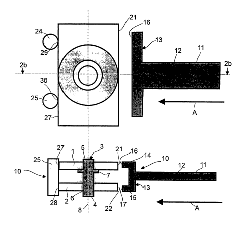
An aligning unit in a first exemplary embodiment of the device in accordance
with invention,
which is schematically shown in Figures 2a and 2b, comprises an abutment
member 11 which
is moved by a not shown displacement unit in the direction of the arrow A in
Figures 2a and
2b. The receiving unit 3 of this exemplary embodiment is moveable.
The abutment member 11 has a shaft 12 which extends in the direction of
movement of the
arrow A and is formed at the end thereof pointing towards the substrate with
an edge seating
CA 02479816 2004-09-17
7 Literal translation of original PCT
or abutment member 13 that extends transversely of the shaft. The edge
abutment member 13
has two protrusions 14 and 15 whose end faces pointing towards the substrates
form abutment
edges 16 and 17 which are adapted to be moved into engagement with the
respective substrate
edges 21 and 22 of the substrates 1 and 2 as can best be perceived in Fig. 2b.
The protrusions
14 and 15 are spaced from one another by a distance which corresponds to the
spacing
maintained by the protrusion 7 between the substrates 1 and 2 on the receiving
unit 3. Thus,
the abutment edges 16 and 17 essentially only come into engagement with the
substrate edges
21 and 22, whereby the abutment edges 16 and 17 have a shape that is
complementary to that
of at least a part of the substrate edges 21 and 22 of the substrates 1 and 2.
In the embodiment
shown with the rectangular substrates 1 and 2 this means that the abutment
edges 16 and 17
are planar and run vertically.
Furthermore, the aligning unit 10 comprises a counter abutment member which
incorporates
two cylindrical pins 24 and 25 in the embodiment of Figures 2a and 2b, said
pins coming into
contact with the substrate edges 27 and 28 of the two substrates at the points
29 and 30 for the
purposes of aligning the two substrates 1 and 2.
In order to join the two rectangular substrates 1 and 2 so as to form a DVD
card, they are
initially accommodated by means of the inner holes 5 and 6 on the pin 4,
whereby the
distance between the two substrates 1 and 2 that is maintained by the pin 4
corresponds to the
spacing between the two protrusions 14 and 15 of the abutment member 11. In
general, the
two substrates 1 and 2 are not usually aligned congruently above one another
at this time
point. Furthermore, the receiving unit 3 is at a distance from the pins 24, 25
at the point in
time at which the substrates 1 and 2 are being seated, that the substrates 1
and 2 will
preferably not come into contact therewith. The abutment member 11 is
subsequently moved
by the displacement unit toward the substrates 1 and 2 until the abutment
edges 16 and I7
come into engagement with the substrate edges 21 and 22.
The displacement unit continues the movement of the abutment member 11 so that
it presses
against the substrate edges 21 and 22. This produces a rotational movement of
the substrates
1 and 2 on the pin 4 until the abutment edges 16 and 17 rest completely
against the substrate
edges 21 and 22 and the latter are arranged congruently in a plan view. At
this time point, the
two substrates 1 and 2 are essentially aligned on the receiving unit 3. In the
course of further
movement of the abutment member 11 against the substrates 1 and 2, the latter
are moved
together with the receiving unit 3 towards the fixed pins 24 and 25. Perfect
alignment is
obtained when the substrate edges 27 and 28 of the substrates 1 and 2 finally
rest against the
points 29 and 30 of the pins 24 and 25.
Alternatively however, the receiving unit 3 could be fixed whereby the process
of aligning the
substrates 1 and 2 is effected entirely by the movement of the abutment member
11.
CA 02479816 2004-09-17
g Literal translation of original PCT
Figures 3a and 3b show a further embodiment of the device in accordance with
the invention.
The device shown in Figures 3a and 3b is designed especially for joining
rectangular
substrates 1 and 2. In like manner to the preceding embodiment, the substrates
1 and 2 are
accommodated in spaced and rotatable manner on a pin 4. An aligning unit in
the
embodiment of Figures 3a and 3b comprises a abutment member 11 which is
moveable in the
direction of the arrow A by a not shown displacement unit and which
incorporates abutment
edges 16 and 17 that are brought into engagement with the substrate edges 21
and 22 of the
rectangular substrates 1 and 2. In this embodiment too, a receiving unit 3 is
moveable
together with the substrates 1 and 2 and they are moved by the abutment member
11 in the
direction of a counter abutment member which comprises two fixed counter
abutment
members 32 and 33. The two fixed counter abutment members 32 and 33 possess
walls 35,
36, 37 and 38. When the abutment member 11 presses the receiving unit 3
together with the
substrates 1 and 2 towards the counter abutment member, the walls 36 and 37
come into
engagement with the long substrate edges 27 and 28 of the substrates 1 and 2.
The walls 35
and 38 however come to rest on the short substrate edges 40 and 41, this being
particularly
helpful in regard to precise alignment of the rectangular substrates 1 and 2.
In the exemplary embodiment of Figures 4a and 4b, a counter abutment member
comprises
further fixed cylindrical pins 43 and 44 in addition to the cylindrical pins
24 and 25 which
were also provided in the embodiment of Figures 2a and 2b, said further
cylindrical pins
coming to rest on the short substrate edges 40 and 41 of the substrates 1 and
2 at the points 45
and 46 so that they are particularly advantageous for aligning the substrates
1 and 2,
especially those having a rectangular shape. In comparison with the exemplary
embodiment
of Figures 3a and 3b however, there is a greater freedom of choice in regard
to the selection of
the peripheral shape of the finally joined DVD cards in the device in
accordance with Figures
4a and 4b.
In Figures Sa and Sb, there is shown an embodiment of the device in accordance
with the
invention wherein a receiving unit 3 is fixed and a abutment member 11 of an
aligning unit is
moved by a not shown displacement unit in the direction of the arrow A. The
abutment edges
16 and 17 of the abutment member 11 are thereby brought into engagement with
the substrate
edges 21 and 22 of the substrates 1 and 2 for producing a rotary aligning
movement of the
substrates.
Furthermore, the aligning unit of the embodiment of Figures Sa and Sb
comprises a moveable
counter abutment member 47 which comprises a shaft 48 and an edge abutment
member 49
that is arranged on the end of the shaft 48 pointing towards the receiving
unit 3. The edge
receiving member 49 has abutment edges 53 and 54 which are formed on the
protrusions 51
and 52.
CA 02479816 2004-09-17
9 Literal translation of original PCT
The counter abutment member 47 is, as it were, the mirror image of the
abutment member 11
and is arranged on the opposite side of the substrates l and 2 from the
abutment member 11.
Like the abutment member 11, the counter abutment member 47 is moved by the
not shown
displacement unit toward the substrate edges 27 and 28 of the rectangular
substrates 1 and 2
in the direction of the arrow B until the abutment edges 53 and 54 eventually
come into
engagement with the substrate edges 27 and 28 of the substrates 1 and 2. Due
to this
movement of the two abutment members 1 l and 47 towards one another and
against the
substrates l and 2 arranged in rotatable manner on the fixed receiving unit 3,
the rectangular
substrates are aligned congruently and can then be joined together to form a
DVD card.
Figures 6a and 6b show a further exemplary embodiment of the device in
accordance with the
invention which comprises an aligning unit matched to a fantasy shape. Two
heart-shaped
substrates 60 and 61 are to be joined to form a DVD which is intended as a
Valentine Card or
some other form of gift article for example. The two heart-shaped substrates
60 and 61 are
accommodated by means of their inner holes 62 and 63 in spaced and rotatable
manner on a
pin 4 of a moveable receiving unit 3. An abutment member 66 comprises a shaft
67 and an
edge abutment member 68 which is arranged at the end of the shaft pointing
towards the
substrates. The abutment member 66 is moved toward the substrates 60 and 61 in
the
direction of the arrow C by a not shown displacement unit. The edge abutment
member 68 is
matched to the substrate edges 70 and 71 of the heart-shaped substrates 60 and
61. In
particular, the edge abutment member 68 comprises two protrusions 73 and 74
having
abutment edges 75 and 76 formed at the ends thereof.
The edge abutment member 68 is formed in such a manner that it can encompass
the substrate
edges 70 and 71 of the heart-shaped substrates 60 and 61. To this end, the
edge abutment
member 68 is preferably somewhat resilient so that it grasps the substrate
edges 70 and 71, as
it were, and thus comes into engagement therewith by virtue of the movement of
the abutment
member 66 in the direction of the arrow C. Due to the further movement of the
abutment
member 66 against the substrates 60 and 61 accommodated on the receiving unit
3, the
receiving unit 3 is moved towards a fixed counter abutment member which
comprises
cylindrical abutment pins 78, 79, 80 and 81 that come to rest at the points
83, 84, 85 and 86
on those substrate edges of the substrates which are opposite the substrate
edges 70 and 71.
As has already been indicated, the counter abutment members can be omitted in
a
modification of the exemplary embodiments described hereinbefore. The
receiving unit 3 is
then fixed and the abutment member 11 or 66 is moved against the substrate
edges of the
substrates. Furthermore, the moveable abutment member could comprise, in like
manner to
the counter abutment members in the embodiments of Figures 2a, 2b, 4a, 4b, 6a,
6b, one or
more moveable cylindrical pins which are arranged such that their cylindrical
axes are parallel
CA 02479816 2004-09-17
Literal translation of original PCT
to the common axis of rotation D, namely, transverse to the substrate edges,
and only come
into contact with the substrates in point-like manner. This enables there to
be a large degree
of flexibility when processing different shapes of substrates since a abutment
member
consisting of cylindrical pins can easily and quickly be matched to any
arbitrary shape of the
substrates by suitable movement or positioning of the pins. The moveable pins
can be
arranged at one side of the substrates or around the substrates.
The two substrates are joined congruently after they have been aligned. To
this end and even
before the substrates are aligned for example, there is applied to a joining
side of at least one
of the substrates an adhesive which may, for example, be a liquid adhesive
film produced by
centrifuging, an adhesive film which consists of just one adhesive layer
without a backing
material, or an adhesive film on a backing material. The device may comprise a
unit that is
suitable for applying the adhesive.
The process of joining the substrates is preferably effected in a vacuum
chamber since defects
in the jointing layer between the substrates, such as trapped bubbles in the
adhesive for
example, can thereby be prevented.
The jointing unit provided for the process of pressing the substrates together
can be a cylinder
station or a membrane station. An example of such a membrane station is
described in the
applicant's unpublished patent application DE 101 00 427 which is incorporated
herein by
reference so as to avoid repetition. Such a membrane station is particularly
suitable for use in
a vacuum chamber.
The device and the method in accordance with invention thus enable non-
circular optical data
carriers consisting of at least two substrates to be produced, whereby precise
alignment and
secure joining of the substrates is attained by simple measures even in the
case of complicated
peripheral shapes.