Note: Descriptions are shown in the official language in which they were submitted.
CA 02480115 2004-09-21
WO 03/084885
PCT/US03/08313
OXYGEN-FIRED FRONT END
FOR GLASS FORMING OPERATION
BACKGROUND OF THE INVENTION
This invention relates in general to forming operations and more particularly
to a
front end for use in forming operations. Most particularly, this invention
relates to an
oxygen-fired front end for use in glass forming operations.
In a forming operation, batch material is reduced to molten substance (for
example,
molten glass) by passing the batch material through a melting furnace, which
is commonly
referred to as a melter. The molten glass is delivered downstream from the
melter through
a system of channels and forehearths. This system of channels and forehearths
is referred
to as a front end. The front end serves as a conduit to deliver the molten
glass to one or
more production points. The front end also serves to cool and condition the
molten glass
prior to reaching the production points. These production points are referred
to as forming
positions. Each forming position includes a bushing for fiber forming
operation or a gob
cutter for a container forming operation. Bushings or gob cutters are secured
to the
forehearths via a forehearth steel.
A conventional forehearth is provided with a firing system, which includes a
plurality of burners. The burner functions to condition the molten glass G and
maintain
the molten glass G at a desired operational temperature. An example of a
conventional
forehearth 10 is shown in Fig. 1. The forehearth 10 includes a top or crown
(not shown), a
bottom (also not shown), and laterally spaced sidewalls 16. Portions of the
forehearth 10
above the level of the molten glass G are constructed from super structure
refractory.
Portions of the forehearth 10 below the level of the molten glass G are
constructed from
contact refractory (that is, glass contact refractory).
A plurality of holes 18 is drilled through the sidewalls 16. The holes 18 are
drilled
through the super structure of the forehearth 10. The holes 18 are drilled at
a right angle
relative to the sidewalls 16. The holes 18 are adapted to receive burners 20.
The holes 18
are spaced about 4-5 inches (10.16-12.7 centimeters) from one another.
Consequently, a
large number of burners, manifolds, pipes, fittings and valves (not shown) are
associated
with air-gas mixture burners.
1
CA 02480115 2004-09-21
WO 03/084885
PCT/US03/08313
In a conventional firing system, a source of air and a source of gas pass
through
regulators. The air and gas are mixed and then passed through a system of
pipes to a
plurality of burners, typically 20 to 100 burners. The burners are typically
air-gas mixture
burners. That is to say, the burners use the air as an oxidant for the
combustion of the gas
to provide heat to a zone, commonly referred to as a control zone. The front
end has
between six and sixty control zones, each complete with a gas control safety
and pressure
reduction system, combustion air blowers, and valves and regulators capable of
controlling
the temperature of the molten glass G between the melter and the forming
position.
An air-gas mixture firing system is not only costly to construct, it is
inefficient to
operate. An air-gas mixture firing system uses 30 to 75 cubic feet per hour
(0.850 to 2.124
cubic meter per hour) of gas to heat a 12-inch (30.48-centimeter) section of
channel with
an air-gas mixture. It requires about 10 cubic feet (0.283 cubic meter) of air
for
combustion of 1 cubic foot (0.0283 cubic meter) of natural gas. The air must
be heated
from an ambient temperature to the same temperature as the exhaust gas stream.
About 70
to 85 percent of the energy used heats the air to the exhaust gas temperature,
leaving less
than 15 to 30 percent of the energy to be transferred as available heat (that
is, heat
available for the glass forming operation). Thus, an air-gas mixture firing
system has
minimum efficiency of combustion.
In addition to having a minimum efficiency of combustion, an air-gas mixture
firing system is an inefficient means to heat the molten glass G. The flame
temperature of
an air-gas mixture burner in the air-gas mixture firing system reaches about
3500 F
(1926.67 C). However, the optical properties of the molten glass G and
products of
combustion limit the amount of radiant energy that penetrates the molten glasS
G. This
causes the temperature gradient to be high vertically through the molten glass
G. The only
way to control the temperature distribution is to control the profile of the
burners.
To overcome the deficiencies of an air-gas mixture firing system, the air-gas
mixture burners have been replaced with concentric-type oxygen-gas mixture
burners. A
typical oxygen-gas firing system is supplied by BH-F)(ENGINEERING) LTD. of
England.
The system uses burners commonly referred to as oxygen-gas burners. Oxygen-gas
burners use oxygen (for example, typically 90 to 99 percent purity with an
impurity being a
combination of nitrogen and argon) in a high purity as an oxidant and fossil
fuel for a
= combustible hydrocarbon supply. The oxygen-gas burner ignites the mixture
of oxygen
2
CA 02480115 2013-04-18
and gas at the point of ignition or combustion. The oxygen-gas burners are
placed 4-5 inches
(10.16-12.7 centimeters) apart, similar to the spacing to the air-gas mixture
burners described
above.
The oxygen-gas burners reduce CO2 and NO, emissions, making these burners more
environmentally friendly and possibly reducing greenhouse gas taxes. Oxygen-
gas burners fire
more efficiently by reducing the waste gas stream and providing more available
heat for use in
the glass forming operation. This holds true because an oxygen-gas burner
requires less volume
(that is, 2 cubic feet (0.0566 cubic meter)) for combustion of 1 cubic foot
(0.0283 cubic meter)
of natural gas. Consequently, exhaust gases (that is, the stream of gas used
to heat the oxygen-
gas mixture) are reduced by about 73 percent. As a result, about 65 percent of
the energy in an
oxygen-gas mixture firing system is used to transfer available heat.
In addition to having a greater efficiency of combustion, an oxygen-gas
mixture firing
system is a more efficient means to heat the molten glass. The flame
temperature of an oxygen-
gas burner is about 4500 F-4800 F (2482.22 C-2648.89 C). At this temperature,
the flame and
products of combustion radiate energy at wavelengths that the molten glass can
absorb. This
provides uniform glass temperature horizontally on the surface of the molten
glass and
vertically through the molten glass.
Although an oxygen-gas mixture firing system provides uniform glass
temperature, it
requires an extensive number of complex and costly components. For example,
the current cost
of an oxygen-gas burner is about $1,000 (903.97 Euro). A conventional oxygen-
gas mixture
system uses about six oxygen-gas burners per foot (30.48 centimeters),
resulting in a cost of
about $6,000 (5,423.80 Euro) per foot (30.48 centimeters).
What is needed is a front end that reduces fuel consumption by using a low-
cost system
for firing forehearths with a combination of gas and oxygen.
SUMMARY OF THE INVENTION
In accordance with one aspect of the present invention, there is provided an
oxygen-
fired front end for use in glass forming operations, the front end comprising:
a top wall, a
bottom wall, and laterally spaced sidewalls, the top, bottom and side walls
defining an
elongated channel configured for the flow of molten glass in the direction of
the length of the
channel, the channel having an upstream end and a downstream end, wherein the
front end
delivers molten glass from a melter to one or more production points; and a
plurality of
3
CA 02480115 2013-04-18
oxygen-fired burners that are arranged to supply substantially all the heat to
the elongated
channel to maintain the molten glass at a desired operational temperature, the
oxygen-fired
burners being structured to substantially function without a source of air,
the oxygen-fired
burners being mounted to extend through the top wall and being oriented to
direct flame and
products of combustion at a downward acute angle relative to the top wall, and
to direct the
flame and products of combustion along the length of the channel, the angle
being such that the
burner flame does not directly contact the sidewalls.
In accordance with another aspect of the present invention, there is provided
an oxygen-
fired front end for use in glass forming operations, the front end comprising:
a top wall, a
bottom wall, and laterally spaced sidewalls, the top, bottom and side walls
defining an
elongated channel configured for the flow of molten glass in the direction of
the length of the
channel, the channel having an upstream end and a downstream end, wherein the
front end
delivers molten glass from a melter to one or more production points; a
plurality of oxygen-
fired burners that are arranged to supply substantially all the heat to the
elongated channel to
maintain the molten glass at a desired operational temperature, the oxygen-
fired burners being
structured to substantially function without a source of air, the oxygen-fired
burners being
mounted to extend through the top wall and configured to direct a flame having
a temperature
of about 4200 degrees to about 5200 degrees F., with the oxygen-fired burners
being oriented
to direct the flame and products of combustion along the length of the
channel, the oxygen-
fired burners being oriented such that the burner flame does not directly
contact the sidewalls;
and additional oxygen-fired burners mounted so that they extend through one of
the sidewalls,
the additional oxygen-fired burners oriented to direct flame and products of
combustion at an
acute angle relative to the sidewalls, the angle being such that the burner
flame from the
additional burners does not directly contact the sidewalls.
In accordance with another aspect of the present invention, there is provided
an oxygen-
fired front end for use in glass forming operations, the front end comprising:
a top wall, a
bottom wall, and laterally spaced sidewalls, the top, bottom and side walls
defining an
elongated channel configured for the flow of molten glass in the direction of
the length of the
channel, the channel having an upstream end and a downstream end; a plurality
of oxygen-fired
burners that are arranged to supply substantially all the heat to the
elongated channel to
maintain the molten glass at a desired operational temperature, the oxygen-
fired burners being
structured to substantially function without a source of air, the oxygen-fired
burners being
4
CA 02480115 2013-07-17
=
mounted so that they extend through the top wall, the oxygen-fired burners
oriented to
direct flame and products of combustion at an acute angle relative to the top
wall, with the
oxygen-fired burners being oriented to direct the flame and products of
combustion along
the length of the channel; and additional oxygen-fired burners that extend
through the side
walls and that are mounted at an acute angle relative to the sidewalls;
wherein the oxygen-
fired burners are oriented so that flame from the oxygen-fired burners does
not contact the
sidewalls, thereby precluding direct flame contact with the sidewalls; and
wherein the
additional oxygen-fired burners that extend through the side walls are
directed toward the
upstream end.
In accordance with another aspect of the present invention, there is provided
an
oxygen-fired front end for use in glass forming operations, the front end
comprising: a top
wall, a bottom wall, and laterally spaced sidewalls, the top, bottom and
sidewalls defining
an elongated channel configured for the flow of molten glass in the direction
of the length
of the channel, the channel having an upstream end and a downstream end,
wherein the
front end delivers molten glass from a melter to one or more production
points; and a
plurality of oxygen-fired burners that are arranged to supply substantially
all the heat to the
elongated channel to maintain the molten glass at a desired operational
temperature, the
oxygen-fired burners being structured to substantially function without a
source of air, the
oxygen-fired burners being mounted to extend through the top wall and being
oriented to
direct flame and products of combustion at a downward acute angle relative to
the surface
of the expected molten glass in the channel, with the oxygen-fired burners
being oriented to
direct the flame and products of combustion along the length of the channel,
the oxygen-
fired burners are disposed to direct the burner flame whereby the burner flame
does not
directly contact the sidewalls.
In accordance with another aspect of the present invention, there is provided
a front
end for a glass forming operation, the front end comprising: a channel having
a top and side
walls, each side wall having upper portions constructed from a super structure
refractory
material and lower portions of the front end constructed from a contact
refractory material,
4a
CA 02480115 2013-07-17
a
the super structure refractory material having a lower resistance to corrosion
than the
contact refractory material; the channel having an upstream end, a downstream
end, and at
least one surface having one or more oxygen-fired burner ports therein; and
one or more
oxygen-fired burners: angled so that the burner flame does not directly
contact the sidewalls,
each oxygen-fired burner arranged to supply heat to molten glass in the
channel to maintain
molten glass at a desired operational temperature, the oxygen-fired burners
being structured
to substantially function without a source of air, the oxygen-fired burners
extending through
a burner port so that the oxygen-fired burners extend toward the upstream end
or the
downstream end at an acute angle relative to the at least one surface and in a
plane
extending between the upstream end and the downstream end and perpendicular to
the at
least one surface, the oxygen-fired burners being disposed to direct the flame
and products
of combustion along the length of the channel, the angle being such that the
flame does not
directly contact the sidewalls.
Some exemplary embodiments of the present invention are directed toward a
front
end for a glass forming operation. The front end may comprise an open ended
channel and
at least one burner. The channel may have at least one surface. The surface
may have at
least one hole therein. The burner may be oriented in the hole at an acute
angle relative to
the surface.
Some exemplary embodiments of the present invention are directed toward a
front
end comprising a channel having a top and a pair of sidewalls each having a
surface. At
least one hole may be in at least one of the surfaces. The hole may be at an
acute angle
relative to at least one surface. The burner may be an oxygen-fired burner.
Some exemplary embodiments of the present invention are directed toward a
front
end comprising a channel having a top and sidewalls each having a super
structure surface
constructed of refractory material. The channel may have an upstream end and a
downstream end. At least one of the surfaces may have a plurality of holes
therein. The
holes may extend at an acute angle relative to at least one surface and in a
plane extending
4b
CA 02480115 2013-07-17
between the upstream end and the downstream end and perpendicular to at least
one surface.
Oxygen-fired burners may extend axially through corresponding holes.
Various features and advantages of this invention will become apparent to
those
skilled in the art from the following detailed description of the preferred
embodiment, when
read in light of the accompanying drawings.
BRIEF DESCRIPTION OF THE DRAWINGS
Fig. 1 is an environmental cross-sectional top plan view of a channel of a
prior art
front end.
Fig. 2 is an environmental cross-sectional top plan view in cross-section of a
channel
according to one embodiment of the invention, wherein burners are
alternatively spaced in
the sidewalls of the channel.
Fig. 3 is an environmental cross-sectional top plan view in cross-section of a
channel
according to another embodiment of the invention, wherein burners are spaced
in pairs in
the sidewalls of the channel.
Fig. 4 is an environmental side elevational view in cross-section of a channel
according to another embodiment of the invention, wherein burners sweep the
top of the
channel.
Fig. 5 is an environmental front elevational view in cross-section of a multi-
zone
channel according to yet another embodiment of the invention.
DETAILED DESCRIPTION OF THE PREFERRED EMBODIMENT
4c
CA 02480115 2013-04-18
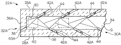
Referring now to the drawings, there is illustrated in Fig. 2 a front end of a
glass
forming operation. The front end comprises an open channel and a forehearth
downstream
of the open channel. To simplify the description, the channel and forehearth
will be
cooperatively described as a channel 22A. The channel 22A is adapted to
deliver molten
substance (for example, molten glass G) from a melter to a point of production
(that is, a
forming position). Neither the melter nor the forming position is shown.
Molten glass G does not contact an upper portion of the channel 22A. That is
to say,
an upper portion of the channel 22A is above the molten glass level (that is,
the molten glass
level L shown in Figs. 4 and 5). Consequently, this portion can be constructed
from
relatively inexpensive refractory material (that is, a super structure
refractory material, such
as silica, mullite, or other materials that are not required to withstand
corrosive effects of
molten glass G).
A lower portion of the channel 22A is below the glass level L and thus comes
into
contact with the molten glass G. Consequently, this portion of the channel 22A
is
constructed of a more costly glass contact refractory material. A ceramic
refractory material
(that is, zircon, chromic oxide, or other suitable material) is a suitable
glass contact
refractory material because it can sustain the corrosive effects of molten
glass G.
The channel 22A may comprise a top or crown (not shown), a bottom (also not
shown), and sidewalls 28A. The channel 22A has an upstream end, generally
indicated at
30A, and a downstream end, generally indicated at 32A. An open end 34 may be
provided
at the upstream end 30A of the channel 22A. An end wall 36A may be provided at
the
downstream end 32A of the channel 22A. One or more glass orifices 38 may be
provided in
the bottom of the chamiel 22A proximate, adjacent or close to the end wall
36A. The
forehearth of the front end, as introduced above, is that portion of the
channel 22A having
the end wall 36A and the glass orifices 38 in the bottom.
The sidewalls 28A each define a surface 40. The surfaces 40 have at least one
hole
42A therein. The hole 42A may be drilled in the super structure refractory
material of
existing front ends with a refractory core drill. New front ends can be
constructed with
built-in burner blocks having holes 42C formed therein (see Fig. 4). A burner
44 is provided
in the hole 42A. In a preferred embodiment of the invention, a plurality of
holes 42A is
provided and a burner 44 is provided in each of the holes 42 A. The burners 44
are
preferably oxygen-fired burners, wherein oxygen (in high purity) and gas are
mixed at a
point of ignition or combustion. That is to say, the burners use oxygen as an
oxidant and
5
CA 02480115 2013-04-18
fossil fuel for a combustible hydrocarbon supply. Such burners are well known
to those of
ordinary skill in the art of the invention.
The burners 44 are positioned above the glass level L (shown in FIGS. 4 and
5). The
burners 44 are oriented in a plane (e.g., a substantially horizontal plane)
perpendicular to the
surfaces 40 and at an acute angle relative to the surfaces 40. In FIG. 2, the
burners 44 are
pointed toward the downstream end 32A of the channel 22A at an acute angle
between
about 5 degrees to about 85 degrees relative to the surfaces 40, as shown in
FIG. 2 with the
angle being measured between a plane coinciding with the longitudinal axis of
the burner 44
which extends outwardly from the burner 44 in the direction of the burner
flame and the
portion of the surface 40 that is the shortest angular distance away from this
plane. It
should be noted that when angle measurements are set forth herein, such angles
are
measured in a similar fashion with the angle being measured between a plane
coinciding
with the longitudinal axis of the burner 44 which extends outwardly from the
burner 44 in
the direction of the burner flame and the portion of the surface of the
channel 22 to which
the burner is referenced as being relative to that is the shortest angular
distance away from
this plane. Alternatively, as shown in FIG. 3, the burners 44 can be pointed
toward the
upstream end 30A of the channel 22A at an acute angle between about 5 degrees
to about
85 degrees relative to the surfaces 40. This embodiment will be described in
greater detail in
the description hereinbelow.
Continuing with reference to Fig. 2, the burners 44 may be staggered or
alternatively
spaced so that opposing burners 44 in the opposing sidewalls 28A are laterally
offset or do
not laterally align (do not vertically align when viewing Fig. 2) with one
another. The flame
temperature of an oxygen-fired burner is about 4200 F-5200 F (2315.56 C-
2871.11 C).
However, the flame is preferably very small. Consequently, the flame does not
directly
contact the sidewalls 28A. However, heat radiating from the flame is quite
substantial.
Although the flame does not directly contact the sidewalls 28A, the sidewalls
28A are
heated sufficiently by convection or heat otherwise radiating from the flame.
This radiant
heat is sufficient to properly condition the molten glass G and maintain the
molten glass G
at a desired temperature without compromising the integrity of the channel 22A
by
exposing the channel 22A to excessively high temperatures. This holds true
even if the
burners 44 are spaced about 1 foot (0.3048 meter) to about 5 feet (1.524
meter) apart from
one another.
6
CA 02480115 2013-04-18
Although not shown, it may be desirable to provide a hole 43A in the end wall
36A
of the channel 22A. This hole 43A may be used as an exhaust hole or to support
another
burner 44 if more heat is needed in this region for conditioning the molten
glass G or to
maintain the molten glass G at a desired temperature.
Another embodiment of the invention is shown in Fig. 3. This embodiment is
similar
to the embodiment described above except the burners 44 are provided in pairs.
In this
embodiment of the invention, opposing burners 44 are not staggered or
alternatively spaced.
Instead, the opposing burners 44 are laterally aligned (vertically aligned
when viewing Fig.
3) with one another, in this embodiment of the invention, more uniform
distribution of heat
may be provided.
In either of the foregoing embodiments of the invention, the burners 44 can be
oriented so that the flames of opposing burners 44 cause one another to
reflect toward the
sidewalls 28A, 28B of the channel 22A, 22B. This is illustrated
diagrammatically by the
conical shaped pattern shown in FIG. 3. It should also be appreciated by one
of ordinary
skill in the art that the burners 44 in the foregoing embodiments could be
angled downward.
For example, the burners 44 could be angled downward at an angle relative to
top 24 in a
range of about 0 degrees to about 20 degrees. As shown in FIG. 4, the angle
can be about 30
degrees.
Another embodiment of the invention is illustrated in FIG. 4. The channel 22C
according to this embodiment of the invention has a surface 46 defined by the
top 24C of
the channel 22C. This surface 46 has at least one hole 42C therein. A burner
44 is provided
in the hole 42C. In a preferred embodiment of the invention, a plurality of
holes 42C is
provided and a burner 44 is provided in each of the holes 42C. The burners 44
are
preferably oxygen-fired burners. As shown in FIG. 4, the oxygen-fired burners
are arranged
to supply substantially all the heat to the elongated channel to maintain the
molten glass at a
desired operational temperature.
The burners 44 may be oriented in a plane (e.g., a substantially vertical
plane)
perpendicular to the surface 46 and at an acute angle relative to the surface
46. In one
embodiment of the invention, the burners 44 are pointed toward the upstream
end 30C of
the channel 22C at an acute angle between about 5 degrees to about 85 degrees
relative to
the surface 46, as shown in FIG. 4. Alternatively, the burners 44 can be
pointed toward the
downstream end 32C of the channel 22C at an acute angle between about 5
degrees to about
85 degrees relative to the surface 46.
7
CA 02480115 2013-04-18
As shown in Figure 4, a hole 43C may be provided in the end wall 36C of the
channel 22C. The hole 43C may be used as an exhaust vent for the channel 22C.
In a
preferred embodiment of the invention, this hole 43C is used to support
another burner 44 if
more heat is needed in this region for conditioning the molten glass G or to
maintain the
molten glass G at a desired temperature. Although, the burner 44 in the hole
43C in the end
wall 36C is preferably oriented at an angle of about 15 degrees relative the
top surface 46,
as shown in Fig. 4, other angles may be suitable for carrying out the
invention. For example,
if the hole 43C is in the end wall 36C, the burner 44 may be at any angle
ranging from
about 5 degrees to about 90 degrees
7a
CA 02480115 2011-06-03
(or horizontal) relative to the end wall 36C. If the hole 43C is in the
junction of the end wall
36C and the top surface 46, the burner 44 can be at any angle ranging from
about 5 degrees to
about 85 degrees relative to the end wall 36C.
Yet another embodiment of the invention is shown in Fig. 5. The channel 22D
according to this embodiment of the invention is a hybrid channel having an
intermediate
cooling channel 48 and diametrically disposed burners 44. Although the burners
44 shown are
provided in the top 24D of the channel 22D, the burners 44 may be provided in
the sidewalls
28D. This embodiment of the invention is useful in wider firing zones where
some cooling is
desired, such as in glass container forming operations. Such operations
typically require
channels that measure about 5 feet (1.524 meter) wide.
In each of the foregoing embodiments of the invention, the burners 44 should
be
oriented so that the burner flame is not pushed into the top 24C, 24D or the
sidewalls 28A, 28B,
28D. Moreover, the burners 44 should also be separated and the flame tempered
so that
excessive levels of heat are not reached within the channel 22A, 22B, 22C,
22D. This avoids
the risk of overheating the top 24C, 24D, the sidewalls 28A, 28B, 28D, and/or
the burner
nozzle, resulting in damage to the refractory material or burners 44. As can
be clearly seen in
FIGS. 2, 3 and 4, the oxygen-fired burners 44 are oriented to direct flame and
products of
combustion in the direction of the length of channels 22A, 22B and 22C,
respectively.
In each of the foregoing embodiments of the invention, the flow of oxygen is
preferably
about 20 to 200 cubic feet per hour (0.566 to 5.663 cubic meter per hour) for
each burner 44.
Any gas that requires this amount of flow for complete combustion may be
suitable for
carrying out the invention. The oxygen demand should be the same independent
of the gas used.
The front end of the invention is advantageous because it uses fewer burners,
fewer
valves, fewer fittings, and a smaller number of associated manifolds and
pipes. Firing is more
efficient, therefore less fuel is consumed. Consequently, fuel pipe sizes are
reduced. There is
also a large reduction of pipe sizes for piping oxygen as opposed to air (for
example, from 8, 6,
or 4 inches (20.32, 15.24, or 10.16 centimeters) to 1 or 2 inches (5.08 or
2.54 centimeters) or
smaller pipe). Installation costs are also reduced.
In accordance with the provisions of the patent statutes, the principle and
mode of
operation of this invention have been explained and illustrated in its
preferred embodiment.
8
CA 02480115 2011-06-03
However, it must be understood that this invention may be practiced otherwise
than as
specifically explained and illustrated without departing from its spirit or
scope.
8a