Note: Descriptions are shown in the official language in which they were submitted.
CA 02480260 2004-09-22
TRANSLATION (HKH-07PC'f):
Ta0 p3/079, $99 A1
PCT/DE03/00,37~
DEVICE AND METHOD FaR MEASURING BLdOD CONSTITUENTS
The invent~.on concerns a method for controlling a device
for measuring quantitative proportions Qf blood co~zstituerzts, in
which elect,rama.gnetzc radiation of different radiation
freqv.encies is passed through a blood-containing vessel, and in
which at least a portion of the rad~.atxvn exiting the vessel is
detected by sensors and fed to an evaluating device_
The invent ion also Concerns a device far measurira,g
quantitative proportions of blood constituents, which has at
least one emission source fvr generating electromagnetic
radiation and at .east one sensor, which detects the transmitted
portion of the radiation and is connected to an evaluating
device.
Methods and devices of these' types are already known in
vaxious embodxmer~ts. For example, t)S Patent G,151,Sx8 describes
a device far determining the corieentrations of certain blood
constituents, in which a part of the living organism is
1
CA 02480260 2004-09-22
transilluminated by a light source, and the portion of the light
that is transmitted by the organism is detected by measurement
techniques arid fed to an evaluating device. A comparable method
is also described in~PCT-WO 00/42905. Another system as
described in PCT-WD 99/39631. J:n this system, a measurc~merlt
device is positioned next to an index finger, which is
transilluminau.ed with a plurality of light sources, and the
reflected components are determined_ SimiJ.ar systems for the
detection of blood constituents by measurement techniques
invol~ring the use of a finger as the site of measurement are
explained in US Patent 6,D64,898 and US Patent 6,149,5$$.
device for measuring the hemoglobin concentration of
blood is described iri DE Patent 7.96 1.2 425, and another device
involving the use of measurement in the area of the finger is
explained in PCT-WO 89/0175$.
A measuring device for the noninvasive determination of the
hemoglobin concentration of blood is already known from the
publication "Jahrestagung der Gesellschaft ftir Eiomedizinische
Mef~technik e.v. CAnr~ual Conference of the Society fbr Biomedical
Measuring Technique], September 28-3D, 2000 in Liibeck, Vol. 45,
Kraitl, Eehxens, Hornberger, Gehring~~.
2
CA 02480260 2004-09-22
A11 prior-art devices have the disadvantage that they are
subjected to a standard calibration based on a collection of
personN that was selected during the development of the given
devices. This can result in relatively high measurement
inac:c:u.r. acy when the de~rice is used for an individual patient,
since the individual histaanatomy with respect to the radiation
transmission of the given patient could nQt be taken into
ccansideration in the general calibration. So far, in many
cases, only a relative change in the spectroscapically measured
substance concentrations curl be determined.
Therefore, the objective of the present invention is to
specify a method of the aforementioned type that allo~rrs
increased measurement accuracy and automatic determination of
the individual characteristics of the patzent, so that an
absolute measurement can be made, i,e., a measurement that is
tied to units and is not merely a relative measurement.
Tnis objective i,s achieved by positioz~i.ng at least two
rad~.ation detection sensors a certain dlstarlCe apart and by
assign,xng to the evaluating device a calibration characteristic
cu~~vp, which is determined by an individual calibration
measurement, in which at least one constant is used as the
3
CA 02480260 2004-09-22
calibration criterion arid is determined from at least one
measured variable detected by the sensors.
A further objective of the invention is to design a device
of the aforementioned type in such a way that improved measuring
quality is achieved.
In accordance with the inventaon, this objective is
achieved by providing the evaluating devxCe with at least two
sensors and with an analyser for determin3.ng the angle-dcpendex~t
scattering of trie radiation by evaluating the signals received
from the individual sensors.
A significant increase in measurement accuracy carx be
achieved by the individual detection of the tissue~dependent
scattering. There is Qrxly a,n ixlsignificant iricxease in the
apparatus expense. xhe time required for the measurement i5 no
greatex.
With respect to measurement technology, the scatter~.ng can
be determined in an especially reliable way by the use of at
least three receiving elements.
An especially simple des~.grr witri respect to measurement
techzaology can be acli.ev~ed by using electromagnetic radzatiox~ in
the visible and infrared frequency range.
4
CA 02480260 2004-09-22
Z~he measurement can be perfoi~ned by the methods of
multiwave pulse spectroscopy.
Tndividualized patient calibrati~rn can be carried out
Without grolonging the measuring time for a blood parameter by
d~tRx'm1111ng the spatial. scattering of the radiation by
measurement technology.
To this end, it is necessary to determine the scattering by
determining a radiation intensity that deviates from the primary
irradiation direction.
To a7.low Compensation of changes ixx parameters (e. g.,
change in sensor position, patient movements) during the
performance of the measurement, it is proposed that a periodic
calibration be carried out dura,ng the perforrnanae o~ the
measurement.
An especially simple e'raluation criterion can be
implemented by determining the scattering by an analysis of the
pulse-cyclical Signals of the measured values of the individual
sensors.
~ preferrod applzcatic~n is the determination of the oxygen
concentration of the blood.
In addition, there is the possibility of determining oxygen
CA 02480260 2004-09-22
concentration relative to a reference quantity in the blood.
zt zs also possible loo det;ermine an absolute oxygen
cc~ncentratian of the blood .
A symmetrical measurement setup can be achieved by
arranging the sensors at essentially equal distarxces (rout one
another. This setup is a special case of a general arrangement
in which this condition is not satisfied.
specific embodiments of the ~.nvention are schematically
illustrated in the drawings.
-- Figt.~re z shows a schematic diagram of a measuring setup.
-- F~.gure 2 shows a schemat~,C block diagram for
illusr.rating arz individual calibration.
-- Ir'igure 3 shows a schematic b3.oclc diagram for
illustrating the determination by measurement technology of a
hemoglobin coxicentration or o~cygez~ saCuration of the blood.
-- rigure 4 shows a typical, absorption spectrum in optical
hemoglobin measurement.
-- Figure S shows t,hQ measurement. variable omega fox three
measuring channels as a function of time.
-- Fxgwre 6 shows a histogram of the measurement variable
atnega for three measuring chanzlels _
6
CA 02480260 2004-09-22
-- Figure 7 shows intensities Eor the three measuring
channels for two varialales each.
--- Figure 8 shows mean va7.ues of the measuring variable
omega far the three measuring channels.
-- Figure 9 shows determined standard deviations of the
measurement varyable omega for the thiee measuring channels.
-- k~igure 10 shows p~,ethysmograms for the three measuring
channels for two variables each.
,- Figure ll Shows a schematic representation fox
illustrating the determination of the values for omega, delta d.,
and the concentration values as a function of the detected
measurement walues_
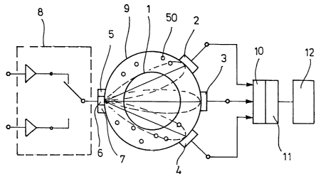
rn the embodiment in Figure Z, which shows a cross section
of a tissue (~) with vessels (1, 50), three sensors (2, 3, 4)
and three emissaon sources (5, 6, 7) are arranged around the
blood-coS.veying tissue (~) . The emission sources (5, 6, 7) ca.n
be. realised, far example, as light-emitting diodes or laser
diodes. Photodiades can be used as the sensors (2, 3,
The emission sources (5, 6, '7) are connected to a
multiplexer (8) for sequential control. The sensors (2, 3, 4)
znd the emission sources (5, G, 7) are preferably placed
7
CA 02480260 2004-09-22
directly on the external surface of tl~e tissue (9) that
surrounds the vessel (1, So). The sensors {2, 3, 4) are
connected to an evaluating device (lo), which is provided with
an analyser (11). Measurement results made available by the
evaluating device (10) can be visualized ox printed out in the
area of a display device (12), and electronic transmission to
deviGSS fdr further proeess.i.ng of the measured values is also
possible.
The block diagram in Figure 2 shows schematically the
sequence of an individual calibration. A standard calibration
function (13) is used to establish, initially a priori, a
patient-independent basic setting, which is then combined with a
scattering determination (14), which is connected to a nzeasur.ing
dc~Vice (15), du~eing the performance of the measuring procedure
for the individual patient. The measuring device {15) detects
the signals of chose sensors (2, 3, 4) that: are not assigned to
an actual primary irradiation direction of the assoc~.ated
emission source (5, 6, 7). The results c~f the standa~cd
calibration function (13) and the output value of the scattering
determination (1~) axe combined wieh each other by a combi.ner
t16) according to an algorithm preset as an zndividua3
8
CA 02480260 2004-09-22
calibration function. An output value of the combines (7.~) is
combined with a measuremesxt variable (17), which is determirzed
from the measured value of that sensor (2, 3, 4) which lies 1I1
the primary irxadia~.ion direction of the associated em~.ssion
source (5, 6, 7) , Comlaxazation of the output value of the
cumJainer (I6) and the measurement variable (17) yields the
re;,pective target q~,antity (18) .
Figure 3 shows a block diagram for explaining an optical.
hernoglabin measurement for determining the oxygen content of the
blood. This measm ring technique is based on the fact that
hemoglobin with hound oxygen shows differel7,t optical absorption
behavi~x from hemoglobin without bound oxygen.
Basically, the block diagram in Figure 3 cons~.sts of two
functional componerzts of the type shown in Figure 2. In this
case, the system cons~.sting of the standard cal~.bration function
(13), the scattering determination (19~), the combines (16), and
the measurerctent vaxiable (17) is connected in parallel w~.Lh
another system Consisting of a standard calibration function
(1~), a scattering determination (20), a combines (21) and a
tneasuremet~t variable (22), The target quantity (18) and the
target quantity (23), which is the output value of the second
9
CA 02480260 2004-09-22
system, are brought together at an interconnect~.on (~4), which
supplies a resulting target quan~.ity (25? as an output value.
Figure 4 shows the typical. absarpt~.vn behavior in a
measurement pf_ the oxygen saturation of the blood_ The
absorption intensity (36) is plotted as a function of the g~.vez1
wavelength (273. A first rninamum occurs at a wavelength of
about 50D am; there ~,s then another increase to a relative
maximum at about 900 nm; and then the curve asymptotically
apprpaches the zero line.
The device in accordance with the invention makes it
possible largely tv eliminate mption artifacts and sensor
relocations, since an automatic calibrat~.ori to the slew optical
path length occurs in each case. This makes it posszble to use
xtze device even on moving patients and quickly to provide the
attending phys~.cian a basis for decid~.rrg what measuzes need to
be taken. Tn this regard, it is taken into account that rapid
movemenLS lead to an .interruption in the flow of measurement
values, whez~eas sensor xelocations with phases of reZati~re rest
do not.
Depending on the specific application reguiremenCS,
different ~ravelengths can be preset. Furthermore, iC is also
io
CA 02480260 2004-09-22
possible to implement different emission characteristics of the
emission sources (5, G, 7). In this regard, the emission,
characteristics can be tightly bundled, for e~cample, or
implemented with a fanned-out radiation lobe,
The individual~.zr~d patient calibration can be carried out
either before the actual perform&nce of the measurement or
periodically during the performance of the measurement.
Especially a periodic determination ire the course of the pulse-
spectroscopic measurement is advantageous. This makes it
possible to compensate far intended or arterial positiar~ chazzges
of the optical sensors (2, 3, 4) or for changes in the
application site during the pez~formarlce of the measurement.
Zn genPxal, a pulse-spectroscopic measurement offers the
advantage that measurement results from tissue and blood can be
supplied with hi.yh measuring accuracy in a very short time and
without invasive methods on the patient, The l3,ght energy
detected by the sensors (2, 3, 4) has a pulsatile compAnent and
am aperiodic component, The pulsati7.e component is a
consequence of the change in the thickness of the blood vessels
i,n correspondence with the Cyclically pulsating flow of blood.
The aperiodic component is the radiation component that exits
~.3
CA 02480260 2004-09-22
after passage ~.hrough the tissue. The light energy varies as a
function of the illumination in.tensi~ty by Lhe partlCUlar
emission sources (S, G, '7) that are selected.
A conaxete a,nstrumental realization of the device described
in Figures x-3 can occur within diff~:rent design pa~:ameter
intervals, depending on the ~.zatended appl.icccta.on. A permissible
transmission wavelength lies w:ithizz a Y-a.rge of ~ mm tQ 3S mm,
preferably a range of S mrn to 30 mm, and especially a range of ~
trim t a ~ 5 mm .
The number of emission elements is ~, and preferably 4.
The emission elements can be used, e.g " in the form of 4x
LEV + 3x L17, preferably 2x LED + Zx hD, arid especially 4x LD.
The wavelengths in the area of the emission elements lie at
55p nm to 1,500 nm, prefexably 6~0 nm to 1,350 nm, and
especially 660 nm to 1,300 nm.
The solid-ar~gle positions of the emissiozi elemexlts lie iI1 a
range of ~~ to 1~9°, preferably 75° to 1~5°, and
especially 85~
to ~5°.
the emission. e7.ements axe preferably centered with a
primary diode in the center and preferably with secondary diodes
on the sides. Basically, however, centering is not necessary.
12
CA 02480260 2004-09-22
The LEDs andJor l,Ds are preferably focused with, a plane
optical flat and especially preferably with a lens. Basically,
however, focusing is not necessary.
The number of detector elements is 2-8, preferably 2-5, and
especiall~r 3.
The solid~angle position of the detector elemenlcs lies
within a, range of -89° to +89°, preferably -2S° to +
35°, and
especially -10° to +1D°.
The r~ormals to the center of the detector surface are
preferably centered with respect to the center emission, arid the
normals to the s~.des ~,re preferably centered on secondary
emissions,
The size of the detector elemexlts 7.ies within a range of 2
mm' to 1D mm~, preferably 2 mm~ to 5 mm~, and especia~.ly 3 mm~,
Basically, the measuring method of the above g~ex~eral
description arid the device that has beers explained carp. be used
for Various applications. Two especially preferred applications
are explained in detail below.
In a pulse-oximetric, patient-indiv~idual~.~ed calibration
(PIC), the most importarxt point is that, in contrast to the
present state of the art, several plethysmograms are recorded by
13
CA 02480260 2004-09-22
photoelectric transducers Ghat have a well-defined spatial
relationship to cane another. The process sequence is described
below and is graphically illu6trated in Figure 11.
These plethysmograms are recorded by each photoelectric
trax~sducer for different wavelengths of emitted radi.ation_ The
wavelengths are taken from the visible (VIS) region and i:he
NzR/IR region of the electromagnetic spectrum.
A measurement variable is formed for mach photodiode ~ by
linking ek~aracteristic propertiES 4f these plethysmograms.
Usirlc~ the pulse-oximetrie measur~.ng~ technique, it is possible
for a measux-ement variak~,le ~ to be determined and for this
vari~.Lle to be assigned to the value of an Qz saturat~,on by a
calibration that is defined a priori.
The process saquence in accordance with the invention takes
all measurement variab3.es and combines them into a 7c~eW
cQrx'ected measurement variable ~Co~ by means of a sensor-specific
crar~sfer function. In addition, this measurement variable is
combined with the tissue-speoific differential attenuation 9.
The tissue.-specific differential attenuation 8 is a measure
of the decrease in radiation intensity within the measureme.~t
site, This ,~ttanuation is obtained by analysis of the
14
CA 02480260 2004-09-22
differencES of all absolute intensities at all z photoelectric
tiransducers.
The photoelectric transducers are arranged in a
geometrically sufficiently well-defined way. Therefore, the
C11a11gC~ in the absolute intensities can be attributed to the
varied Sight paths for individual patients.
The differential attenuation 9 follows fxom the combined
absorption and deflection (scattering and refraction) of photons
at the measurement site. The components of these individual
processes do noC have to be separately determined for the
present method.
The differential atCenuation 8 e.nd the corrected
measurement variable determine the target. quantity of the
method, namely, the arterial oxygen saturatipri, by the
calibration function of the invention. The following i~ the PxC
correction function:
( ~ K _ p'~i. ~~a: )
~C'.orr - t 1~ ~ z
The ~cna~.fiable ~,,~n represents the resulting mea,~urement
variable, which is assigned to the arterial oxygen saturation by
the calibratiarl function
sa0= = g (~~or~ )
is
CA 02480260 2004-09-22
The factors Kla, K~x, and Kaa are validated and adapted by an
empixicaZ (cJ.inical) analysis.
The behavior of the calibration Function g (r.r) correspamds
to the well-known, empirically determined caZibratiQn at the
appl i.cation sits of pulse oxirnetxy.
Another preferred application of the invention is the
aoninvasi~re cont~~.nuous detex'mination of the hemoglobin.
concentration.
The determination of the hemoglobin concentration is based
ran the patient-individualized calibration (pTC). Without this
~:aiibration, art absolute determination, i.e., a quantity with a
pl~ysl~;a1 un:i.t; of measure (here [mg/dL] ) ,~ cannot be performed
with sufficient accuracy.
The attenuation of substance concentrations within a tissue
can be derived by the method of pulse spectroscopy only from the
product o~ the change in thickness and trie substance
concen~:.~wtion .
In( I ' I )
l~c~ ~ C:' _ (~~'Z .- ~~ ) . y~ _ z
~F(~,)-.xsY
N
In the above formula:
C- concentxatian of the desired substance
1~
CA 02480260 2004-09-22
Ad. change in thickness of the pulse-Spectroscopic
target tissue
Z, and I,: VIS / NIR / NR intensities after passage through
the tissue
t(~l: wavelength-dependent absarbances of the substance
derivatives x of S
s~: saturation of the substance 8 with the derivative
x
N: number of spectroscopically relevant substances at
the site Of measurement.
The thickness change in the pulsatit~,gr vessels is associated
w~.th a pulse-cyclical change in transm~,ssion. This is the basis
of each plethysmogram, The amplitude pf plethysmograms is
defined by three characteristics:
1. 1'he pulse-cyclical vascular diameter change D;
2 . The absorba.nces sn (1~) of the substance concentrations
contained in it at the time of measurement; and
3. The modifzcatian of the ab5orbance en(,~) of pulse-
cyclical attenuations in the accompanying rissue_
The absorbance e~(~~ is differentiated from the vascular
thickness change D by an additiana7. NIR / IR emission, i.a., by
17
CA 02480260 2004-09-22
the so-called reference measurement. In the region of the
measux'ement wavelength, this NIR / TR emission should not
experience any appreciable (concentration-dependent) absorption
in the blood constituents to be measured. Tts absorption should
oreur pr imax'i a.y in watex'.
Due to the modification of attenuations in the accompanying
tissue, the determinativiz is again made by the differential
attenuation 0 introduced under PTC. A determination is thus
made of what signal change is produced in the photoelectric
transducers bar a specific change in absorpt.ian.
with the use of the water reference measurement and the
differential attenuation 6, the hemoglobin concentration is then
calculated from the given conditional equation on the basis of
the 3cnawn relative concentrations (saturations).
N
~~~~~~~~~~~~fn~~)~.~~~~~s~~~
»=j
In the above formula:
0d: differential thickness Change of Gho pulsat~.ng
arterial tissue components
I~l: number of hemoglobin derivatives in the patient
~1: counting varic~b7.e
28
CA 02480260 2004-09-22
F~,(~): wavelength-dependent spectral extinction of the Hb
fraction r)
K. VIS / NIR LIR) atter~,uat~.on for photoelectric
trar~sducer No. Z
sax"_ saturation of the total hemoglobin by the fraction
s~ ; Example : X,~ = CO, i . a . , saCO.
The hemoglobin measurement is thus accessible to a
COmtinupus, npnll~vdSlve Irie~SLZrEment.
The de.ri.vatives saX,, are detexrnined in a novel way by the
use o~ the PTC methodology. This more exact method of
determination is a prerequisite for a sufficiently e~aet
determination of the desired substance concentration cHb.
The lileewise novel measurement of the attenuation (~ also
enters into the conditional equation.
19