Language selection

Search

Patent 2480885 Summary

Third-party information liability

Some of the information on this Web page has been provided by external sources. The Government of Canada is not responsible for the accuracy, reliability or currency of the information supplied by external sources. Users wishing to rely upon this information should consult directly with the source of the information. Content provided by external sources is not subject to official languages, privacy and accessibility requirements.

Claims and Abstract availability

Any discrepancies in the text and image of the Claims and Abstract are due to differing posting times. Text of the Claims and Abstract are posted:

  • At the time the application is open to public inspection;
  • At the time of issue of the patent (grant).
(12) Patent: (11) CA 2480885
(54) English Title: ARRANGEMENT AT A ROTATOR
(54) French Title: SYSTEME D'UN ROTATEUR
Status: Expired and beyond the Period of Reversal
Bibliographic Data
(51) International Patent Classification (IPC):
  • B66C 13/08 (2006.01)
  • E02F 03/36 (2006.01)
(72) Inventors :
  • HARR, JOAKIM (Sweden)
(73) Owners :
  • INDEXATOR ROTATOR SYSTEMS AB
(71) Applicants :
  • INDEXATOR ROTATOR SYSTEMS AB (Sweden)
(74) Agent: SMART & BIGGAR LP
(74) Associate agent:
(45) Issued: 2011-01-11
(86) PCT Filing Date: 2003-04-01
(87) Open to Public Inspection: 2003-10-09
Examination requested: 2008-03-28
Availability of licence: N/A
Dedicated to the Public: N/A
(25) Language of filing: English

Patent Cooperation Treaty (PCT): Yes
(86) PCT Filing Number: PCT/SE2003/000522
(87) International Publication Number: SE2003000522
(85) National Entry: 2004-09-29

(30) Application Priority Data:
Application No. Country/Territory Date
0200994-2 (Sweden) 2002-04-02

Abstracts

English Abstract


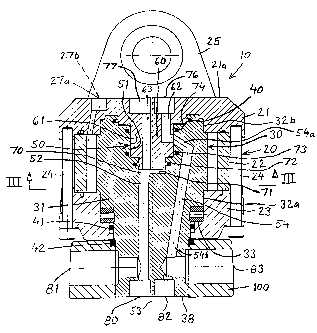
The present invention relates to a rotator arrangement, particularly for arm-
carried working appliances, wherein the rotator (10) includes a stator (20), a
rotor (30) and a swivel coupling/swivel device (50) for medium transfer
between stator (20) and rotor (30), wherein the swivel device (50) is arranged
within the rotor (30). The rotator (10) includes an upper stator wall (21),
which carries an outwardly projecting portion (60) that forms a part of the
swivel device (50), and the rotor shaft (31) has a recess (51) which also
forms a part of the swivel device (50). The rotor shaft (31) includes at least
one working medium transfer channel (54) that connects at least partially
radially with a recess (51) in the rotor shaft (31). The rotor shaft (31)
includes a channel (52) that connects generally axially with a recess (51) in
the rotor shaft (31). The outwardly projecting portion (60) of the upper
stator wall (21) and/or the rotor shaft (31) includes at least one ring groove
(61) for co-action with one (54) of the rotor shaft (31) channels.


French Abstract

La présente invention concerne un système rotateur destiné notamment à des outils de travail à bras-support. Le rotateur (10) comprend un stator (20), un rotor (30) et un couplage articulé/dispositif pivotant (50) destiné au transfert d'un agent entre le stator (20) et le rotor (30). Le dispositif pivotant (50) est placé dans le rotor (30). Le rotateur (10) comprend une paroi stator supérieure (21) qui porte une partie en saillie vers l'extérieur (60), laquelle constitue une partie du dispositif pivotant (50) et l'arbre rotor (31) a un évidement (51) qui constitue également une partie du dispositif pivotant (50). L'arbre rotor (31) comprend au moins un canal (54) qui est destiné au transfert de l'agent de travail (54) et est radialement et au moins partiellement relié à un évidement (51) de l'arbre rotor (31). Le partie en saillie vers l'extérieur (60) de la paroi stator supérieure (21) et/ou de l'arbre rotor (31) comprend au moins une gorge (61) destinée à la coopération avec un (54) des canaux de l'arbre rotor (31).

Claims

Note: Claims are shown in the official language in which they were submitted.


7
CLAIMS
1. A rotator, particularly intended for arm-carried working appliances,
wherein the
rotator (10) includes a stator (20), a rotor (30) and a swivel coupling/swivel
device (50) for
the transfer of working medium between stator (20) and rotor (30),
characterised in that
the swivel device (50) is arranged within the rotor (30).
2. A rotator according to Claim 1, characterised in that said rotator includes
an upper
stator wall (21) which carries an outwardly projecting portion (60) that forms
a part of the
swivel device (50).
3. A rotator according to Claim 1 or 2, characterised in that the rotor shaft
(31)
includes a recess (51) which forms part of the swivel device (50).
4. A rotator according to any one of Claims 1-3, characterised in that the
rotor shaft
(31) includes at least one medium transfer channel (54) that connects at least
partially
radially with a recess (51) in the rotor shaft (31).
5. A rotator according to any one of Claims 1-4, characterised in that the
rotor shaft
(31) includes a channel (52) that connects generally axially with a recess
(51) in the rotor
shaft (31).
6. A rotator according to any one of Claims 2-5, characterised in that the
outwardly
projecting portion (60) of the upper stator wall (21) and/or the rotor shaft
(31) includes at
least one ring groove (61) for co-action with one (54) of the rotor shaft
channels.
7. A rotator according to any one of Claims 1-6, characterised in that the
rotor shaft
(31) includes a channel (54) which has a generally radial part (54a) and a
generally axial
part (54b).
8. A rotator according to any one of Claims 1-7, characterised in that the
rotor shaft
(31) includes a generally axial channel (52) which extends from a bottom
surface (71) of a
recess (51) in the rotor shaft (31) to the lower end (38) of said rotor shaft.

8
9. A rotator according to any one of Claims 4-8, characterised in that the
rotor shaft
channels (52,54) extend to connection points (80,82) in the lower end surface
(38) of the
rotor shaft (31) and/or to radial connection points (81,83) in a clamping ring
(100) on the
rotor shaft.
10. A rotator according to any one of Claims 3-9, characterised by a gap or a
space (70)
between a bottom surface of the downwardly projecting portion (60) of the
upper stator
wall (21) and a bottom surface (71) of the rotor shaft recess (51).
11. A rotator according to any one of Claims 1-10, characterised in that the
upper stator
wall (21) includes connection points (76,77) and/or channels (62,63) that
communicate
with the channels (52,54) of the rotor shaft (31).

Description

Note: Descriptions are shown in the official language in which they were submitted.


CA 02480885 2004-09-29
WO 03/082725 PCT/SE03/00522
ARRANGEMENT AT A ROTATOR
The present invention relates to a rotator arrangement for jib-carried or
crane-arm carried
working appliances in accordance with the preamble of Claim 1.
Rotators intended for crane-carried working appliances normally include a
swivel coupling
which enables efficient orientation of hydraulic hoses. The rotator swivel
coupling is used
to transfer hydraulic medium to the working appliance concerned and/or to
rotate the
rotator. Unfortunately, the swivel coupling takes-up a relatively large amount
of space,
1o meaning that the rotator will be relatively large in height and relatively
heavy.
One object of the present invention is to provide a swivel-equipped rotator
which, among
other things, is compact, light in weight, and enables hoses to be orientated
efficiently in a
highly beneficial manner. This object is fulfilled by the invention, having
the characteristic
1s features set forth in the accompanying Claims.
The following advantages are among those afforded by the invention.
The rotator has a very simple construction, and is compact and light in
weight. This latter
2o feature is extremely meaningful, since the weight of the rotator is
included in the weight
carried by the arm or jib of the working machine. The rotator is very reliable
and is
subjected to low axial stresses or thrust forces as a result of the design of
the swivel
arrangement. Another advantage resides in the number of possible alternative
hose
connections.
The rotator also affords both technical and economical advantages.
The invention will now be described in more detail by way of example and with
reference
to the accompanying drawings, in which Fig. 1 is a side view of an inventive
rotator fitted
3o to the tip of a crane arm and carrying a harvesting unit; Fig. 2 is a
vertical sectioned view
of the rotator; Fig. 3 is a sectioned view of the rotator taken along the line
III-III in Fig. 2;
and Figs. 4 and 5 show two further embodiments of the invention.

CA 02480885 2004-09-29
WO 03/082725 PCT/SE03/00522
2
Shown in Fig. 1 is a working appliance in the form of a so-called single grip
harvesting
unit 1 which is suspended from the tip 2 of a machine-carried working
arm/crane arm 3
through the medium of a rotator 10. The rotator 10 is suspended from a pivot
means 4,
which allows the appliance 1 to swing via the tip of the working arm. The
rotator 10
enables the appliance 1 to rotate relative to the tip 2 of the working arm. A
pair of
hydraulic hoses 5 function to supply the rotor 10 with the requisite hydraulic
oil, and a
number of hydraulic hoses 6 function to supply the appliance 1 with requisite
hydraulic oil.
Although not shown, the hoses 5,6 are connected to a vehicle-carried source of
hydraulic
oil.
As will be seen from Figs. 2 and 3, the rotator 10 comprises a stator 20,
which includes an
upper stator wall 21, a stator ring 22, and a lower stator wall 23. The stator
walls 21,23 and
the stator ring 22 are held together by a number of screws 24.
The upper stator wall 21 includes two attachment lugs 25 for coupling the
rotator to the
working arm 3.
A rotor 30 is mounted within the stator 20. The rotor 30 includes a shaft 31
and is via two
radial bearings 32a,32b and via an axial bearing 33 rotatable relative to the
stator 20. The
2o illustrated rotator 10 is of the so-called wing type, meaning that spring-
biased wings 34 on
the rotor 30 together with the inner surface 26 of the stator and the outer
surface 35 of the
rotor define the working chambers 36,37 required for rotational operation of
the rotator.
The rotator is able to rotate through several revolutions and its direction of
rotation is
reversible.
Pressure medium is supplied to the rotator through hoses 5 connected to
connection points
27a,27b which communicate with the working chambers 36,37 of the rotator
through the
medium of a number of channels. Although only two channels 28,29 are shown in
Fig. 3, it
will be understood that further channels are provided for the working
chambers.
The rotator has an upper seal 40 and two lower seals 41,42.

CA 02480885 2004-09-29
WO 03/082725 PCT/SE03/00522
3
A clamping ring 100 is non-rotatably mounted on the lower end 38 of the rotor
shaft 31,
said clamping ring 100 supporting the working appliance 1, so that rotational
movement of
the rotator will be transferred to said appliance.
The inventive rotator includes a rotor 30, which has at its upper end a swivel
device 50 and
pressure medium channels connecting therewith. According to the invention, the
upper end
of the rotor shaft 31 has a circular recess 51, which forms part of the swivel
device. The
rotor shaft 31 has a first axial channel 52 located in the vicinity of the
rotor centre line 53,
and a second channel 54 which connects generally radially, or at least
partially radially,
1o with the upper recess 51 of the rotor and then detours to a generally axial
direction through
the rotor shaft 31, as illustrated in Fig. 2. The channel 54 thus has a radial
portion 54a and
an axial portion 54b.
In accordance with the invention, the upper stator wall 21 has a downwardly
and outwardly
protruding central portion 60 which is adapted to fit into the rotor recess 51
essentially
with a so-called shape fit. The portion 60 forms a part of the swivel device
50. The central
portion 60 is circular and has a circumferentially extending ring groove 61,
which
communicates with the channel 54 of the rotor shaft 31. A communication
channel 62 for
pressure medium is provided in the upper state wall 21 and communicates with
the ring
2o groove 61. There is thus obtained permanent communication between the
channel 62 and
the channel 54, regardless of the rotational position of the rotor 30 relative
to the stator 20.
A further pressure medium communication channel 63 is provided in the upper
stator wall
21, said channel 63 communicating with a cavity 70 between the downwardly and
outwardly projecting portion 60 of the upper stator wall 21 and a bottom
surface 71 of the
recess 51 in the rotor 30. There is thus obtained constant communication
between the
channel 63 and the channel 52, regardless of the rotational position of the
rotor 30 relative
to the stator 20. A number of seals 72-74 are disposed between the outwardly
protruding
portion 60 and the rotor recess 51, to prevent leakage of pressure medium.
The rotator 10 of the Fig. 2 embodiment is supplied with pressure medium via
the
connection points 27a,27b and associated communications channels in the upper
stator
wall 21, of which only one connection point and one channel have been shown in
the
figure. In the case of the illustrated embodiment, the connection points
27a,27b are situated
on the top surface 21a of the upper stator wall 21. The connection points 76
and 77 of

CA 02480885 2004-09-29
WO 03/082725 PCT/SE03/00522
4
respective channels 62 and 63 are also situated on the top surface 21a of said
wall 21. The
channel 52 in the rotor 30 has an axial connection point 80 in the lower end
38 of the rotor
shaft and also a radial connection point 81 via the clamping ring 100, wherein
alternative
connection points that are not used are plugged. Similarly, the channel 54 in
the rotor 30
has an axial connection point 82 in the lower end 38 of the rotor shaft and a
radial
connection point 83 via the clamping ring 100, wherein alternative connection
points that
are not used are plugged. Thus, this embodiment enables all pressure medium
supply hoses
to be connected to the top surface 21 a of the upper stator wall, wherewith
the rotator 10 is
supplied with pressure medium via the connection points 27a,27b, and the
working
1o appliance 1 is supplied with its pressure medium via the connection points
76,77, at the
same time as hose communication 7 is, of course, arranged between, e.g., the
connection
points 80,82 or the connection points 81,83 and the working appliance 1. This
embodiment
thus provides many beneficial hose orientation options.
In the case of the embodiment illustrated in Fig. 4, a radial hose connection
is provided on
the side surface 21b of the stator wall 21. As will be seen, connection points
90a,90b for
rotator drive medium and connection points 92,93 for working appliance drive
medium are
provided on the side surface 21b of the stator wall. The channel configuration
in the upper
stator wall 21 has, of course, been adapted to the placement of the connection
points.
In the case of the Fig. 5 embodiment, the channel configuration of the upper
stator wall 21
is such as to enable the rotator 10 to be supplied with pressure medium either
via the
connection points 80,82 in the rotor 30 or via the connection points 81,83 in
the rotor-
carried clamping ring 100. Those connection points that are not used at that
particular time
are, of course, plugged. Thus, in this embodiment the hose connections are on
the rotor 30
or on the clamping ring 100, which both accompany the twisting or rotating
movement of
the appliance 1. This simplifies orientation of the hoses in the case of
construction
variations in which the rotator 10 is supplied with pressure medium via the
working
appliance 1, which therewith is supplied with pressure medium via hoses 8, for
instance.
3o For reasons of a processing/technical nature, end plugs 95 are provided in
the channels
96,97 in the upper stator wall 21.
The presence of the partially radial channel portion 54a in the rotor 30 means
that no
additional axial force or thrust will occur on the rotator 10 as a result of
the supply of

CA 02480885 2004-09-29
WO 03/082725 PCT/SE03/00522
pressure medium via the channel 54, which is highly beneficial from the aspect
of stress.
The medium-conducting channel 54 will preferably be used so as to be pressure-
activated
when the working appliance 1 is load bearing.
5 On the other hand, an additional axial force or thrust will occur in the
rotator 10 when
pressure medium is supplied via the channel 52 in the rotor 30, due to
pressurisation of the
space 70. The medium conveying channel 52 will preferably be used so as to be
pressure
activated when the working appliance 1 is not load bearing. Consequently, the
last
mentioned additional axial force will have no deleterious effect on the
rotator, but will
1o instead enhance the working conditions of the thrust bearing 33. The swivel
device 50
includes a shoulder part 98 that has a seal 72,73 on both sides thereof.
When no additional thrust force is desired from the swivel device 50, the
channel system
63,52 can be replaced by a further channel system similar to the channel 62,54
and a
further ring groove similar to the ring groove 61.
When more than two pressure medium transmission points are desired through the
swivel
device 50, this can be achieved by further channel systems corresponding in
principle to
the channels 62,54 and a further ring groove corresponding in principle to the
ring groove
61.
It will be understood that the principle according to which the rotator is
driven and the
structural design of the rotator can be varied widely within the scope of the
invention, and
that the earlier mentioned wing drive may be replaced, e.g., with many
alternative types of
rotational drive means.
A significant advantage provided by the present invention is that the swivel
coupling/swivel device 50 is arranged within the rotorlthe rotor shaft such as
to make
possible many different pressure medium connection alternatives, whilst
eliminating
3o undesirable thrust additions.
As will be understood, the configuration of the pressure medium channels may
be varied
according to requirements and desires within the scope of the inventive
concept. The ring
groove or ring grooves may also be provided in the end-recess of the rotor
shaft.

CA 02480885 2004-09-29
WO 03/082725 PCT/SE03/00522
6
The channels 63 and 52 may also be positioned to coincide with the rotor
centre line 53.
The structural design of the channel 54 and its extension may, of course, be
varied,
provided that the transition between the channels 62 and 54 will allow the
continuous
s transfer of pressure medium.
As will be understood, variations can be applied to the inventive arrangement,
by replacing
the described components with functionally equivalent components.
1o Thus, the invention is not restricted to the illustrated and described
embodiments thereof,
since modifications and variations are possible within the scope of the
accompanying
Claims.

Representative Drawing
A single figure which represents the drawing illustrating the invention.
Administrative Status

2024-08-01:As part of the Next Generation Patents (NGP) transition, the Canadian Patents Database (CPD) now contains a more detailed Event History, which replicates the Event Log of our new back-office solution.

Please note that "Inactive:" events refers to events no longer in use in our new back-office solution.

For a clearer understanding of the status of the application/patent presented on this page, the site Disclaimer , as well as the definitions for Patent , Event History , Maintenance Fee  and Payment History  should be consulted.

Event History

Description Date
Time Limit for Reversal Expired 2020-08-31
Inactive: COVID 19 - Deadline extended 2020-08-19
Inactive: COVID 19 - Deadline extended 2020-08-06
Inactive: COVID 19 - Deadline extended 2020-07-16
Inactive: COVID 19 - Deadline extended 2020-07-02
Inactive: COVID 19 - Deadline extended 2020-06-10
Inactive: COVID 19 - Deadline extended 2020-05-28
Inactive: COVID 19 - Deadline extended 2020-05-14
Inactive: COVID 19 - Deadline extended 2020-04-28
Inactive: COVID 19 - Deadline extended 2020-03-29
Change of Address or Method of Correspondence Request Received 2019-11-20
Common Representative Appointed 2019-10-30
Letter Sent 2019-04-01
Letter Sent 2015-03-17
Inactive: Office letter 2014-03-13
Inactive: Correspondence - Transfer 2014-02-19
Letter Sent 2014-01-31
Inactive: Cover page published 2011-01-11
Grant by Issuance 2011-01-11
Inactive: Final fee received 2010-10-22
Pre-grant 2010-10-22
Notice of Allowance is Issued 2010-05-03
Letter Sent 2010-05-03
Notice of Allowance is Issued 2010-05-03
Inactive: Approved for allowance (AFA) 2010-04-27
Amendment Received - Voluntary Amendment 2010-03-26
Inactive: S.30(2) Rules - Examiner requisition 2010-03-09
Amendment Received - Voluntary Amendment 2009-12-23
Inactive: S.30(2) Rules - Examiner requisition 2009-08-21
Letter Sent 2008-06-10
All Requirements for Examination Determined Compliant 2008-03-28
Request for Examination Requirements Determined Compliant 2008-03-28
Request for Examination Received 2008-03-28
Letter Sent 2005-10-26
Inactive: Single transfer 2005-09-29
Inactive: Cover page published 2004-12-08
Inactive: Courtesy letter - Evidence 2004-12-07
Inactive: Notice - National entry - No RFE 2004-12-06
Application Received - PCT 2004-11-01
National Entry Requirements Determined Compliant 2004-09-29
Application Published (Open to Public Inspection) 2003-10-09

Abandonment History

There is no abandonment history.

Maintenance Fee

The last payment was received on 2010-03-25

Note : If the full payment has not been received on or before the date indicated, a further fee may be required which may be one of the following

  • the reinstatement fee;
  • the late payment fee; or
  • additional fee to reverse deemed expiry.

Patent fees are adjusted on the 1st of January every year. The amounts above are the current amounts if received by December 31 of the current year.
Please refer to the CIPO Patent Fees web page to see all current fee amounts.

Owners on Record

Note: Records showing the ownership history in alphabetical order.

Current Owners on Record
INDEXATOR ROTATOR SYSTEMS AB
Past Owners on Record
JOAKIM HARR
Past Owners that do not appear in the "Owners on Record" listing will appear in other documentation within the application.
Documents

To view selected files, please enter reCAPTCHA code :


To view images, click a link in the Document Description column. To download the documents, select one or more checkboxes in the first column and then click the "Download Selected in PDF format (Zip Archive)" or the "Download Selected as Single PDF" button.

List of published and non-published patent-specific documents on the CPD .

If you have any difficulty accessing content, you can call the Client Service Centre at 1-866-997-1936 or send them an e-mail at CIPO Client Service Centre.


Document
Description 
Date
(yyyy-mm-dd) 
Number of pages   Size of Image (KB) 
Representative drawing 2004-09-28 1 37
Description 2004-09-28 6 302
Abstract 2004-09-28 1 81
Drawings 2004-09-28 5 151
Claims 2004-09-28 2 64
Claims 2004-09-29 2 69
Description 2009-12-22 6 304
Claims 2009-12-22 2 90
Claims 2010-03-25 1 47
Representative drawing 2010-12-14 1 27
Reminder of maintenance fee due 2004-12-05 1 110
Notice of National Entry 2004-12-05 1 192
Request for evidence or missing transfer 2005-10-02 1 100
Courtesy - Certificate of registration (related document(s)) 2005-10-25 1 106
Reminder - Request for Examination 2007-12-03 1 118
Acknowledgement of Request for Examination 2008-06-09 1 177
Commissioner's Notice - Application Found Allowable 2010-05-02 1 164
Maintenance Fee Notice 2019-05-12 1 180
PCT 2004-09-28 10 409
Correspondence 2004-12-05 1 25
Fees 2005-03-28 1 27
Fees 2006-03-27 1 25
Fees 2007-03-20 1 28
Fees 2008-03-27 1 32
Fees 2009-03-29 1 34
Fees 2010-03-24 1 35
Correspondence 2010-10-21 1 35
Fees 2011-03-30 1 34
Correspondence 2014-03-12 1 12