Sélection de la langue

Search

Sommaire du brevet 2480885 

Énoncé de désistement de responsabilité concernant l'information provenant de tiers

Une partie des informations de ce site Web a été fournie par des sources externes. Le gouvernement du Canada n'assume aucune responsabilité concernant la précision, l'actualité ou la fiabilité des informations fournies par les sources externes. Les utilisateurs qui désirent employer cette information devraient consulter directement la source des informations. Le contenu fourni par les sources externes n'est pas assujetti aux exigences sur les langues officielles, la protection des renseignements personnels et l'accessibilité.

Disponibilité de l'Abrégé et des Revendications

L'apparition de différences dans le texte et l'image des Revendications et de l'Abrégé dépend du moment auquel le document est publié. Les textes des Revendications et de l'Abrégé sont affichés :

  • lorsque la demande peut être examinée par le public;
  • lorsque le brevet est émis (délivrance).
(12) Brevet: (11) CA 2480885
(54) Titre français: SYSTEME D'UN ROTATEUR
(54) Titre anglais: ARRANGEMENT AT A ROTATOR
Statut: Périmé et au-delà du délai pour l’annulation
Données bibliographiques
(51) Classification internationale des brevets (CIB):
  • B66C 13/08 (2006.01)
  • E02F 3/36 (2006.01)
(72) Inventeurs :
  • HARR, JOAKIM (Suède)
(73) Titulaires :
  • INDEXATOR ROTATOR SYSTEMS AB
(71) Demandeurs :
  • INDEXATOR ROTATOR SYSTEMS AB (Suède)
(74) Agent: SMART & BIGGAR LP
(74) Co-agent:
(45) Délivré: 2011-01-11
(86) Date de dépôt PCT: 2003-04-01
(87) Mise à la disponibilité du public: 2003-10-09
Requête d'examen: 2008-03-28
Licence disponible: S.O.
Cédé au domaine public: S.O.
(25) Langue des documents déposés: Anglais

Traité de coopération en matière de brevets (PCT): Oui
(86) Numéro de la demande PCT: PCT/SE2003/000522
(87) Numéro de publication internationale PCT: WO 2003082725
(85) Entrée nationale: 2004-09-29

(30) Données de priorité de la demande:
Numéro de la demande Pays / territoire Date
0200994-2 (Suède) 2002-04-02

Abrégés

Abrégé français

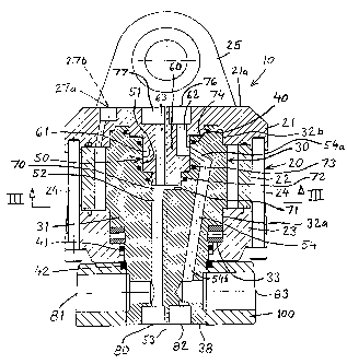
La présente invention concerne un système rotateur destiné notamment à des outils de travail à bras-support. Le rotateur (10) comprend un stator (20), un rotor (30) et un couplage articulé/dispositif pivotant (50) destiné au transfert d'un agent entre le stator (20) et le rotor (30). Le dispositif pivotant (50) est placé dans le rotor (30). Le rotateur (10) comprend une paroi stator supérieure (21) qui porte une partie en saillie vers l'extérieur (60), laquelle constitue une partie du dispositif pivotant (50) et l'arbre rotor (31) a un évidement (51) qui constitue également une partie du dispositif pivotant (50). L'arbre rotor (31) comprend au moins un canal (54) qui est destiné au transfert de l'agent de travail (54) et est radialement et au moins partiellement relié à un évidement (51) de l'arbre rotor (31). Le partie en saillie vers l'extérieur (60) de la paroi stator supérieure (21) et/ou de l'arbre rotor (31) comprend au moins une gorge (61) destinée à la coopération avec un (54) des canaux de l'arbre rotor (31).


Abrégé anglais


The present invention relates to a rotator arrangement, particularly for arm-
carried working appliances, wherein the rotator (10) includes a stator (20), a
rotor (30) and a swivel coupling/swivel device (50) for medium transfer
between stator (20) and rotor (30), wherein the swivel device (50) is arranged
within the rotor (30). The rotator (10) includes an upper stator wall (21),
which carries an outwardly projecting portion (60) that forms a part of the
swivel device (50), and the rotor shaft (31) has a recess (51) which also
forms a part of the swivel device (50). The rotor shaft (31) includes at least
one working medium transfer channel (54) that connects at least partially
radially with a recess (51) in the rotor shaft (31). The rotor shaft (31)
includes a channel (52) that connects generally axially with a recess (51) in
the rotor shaft (31). The outwardly projecting portion (60) of the upper
stator wall (21) and/or the rotor shaft (31) includes at least one ring groove
(61) for co-action with one (54) of the rotor shaft (31) channels.

Revendications

Note : Les revendications sont présentées dans la langue officielle dans laquelle elles ont été soumises.


7
CLAIMS
1. A rotator, particularly intended for arm-carried working appliances,
wherein the
rotator (10) includes a stator (20), a rotor (30) and a swivel coupling/swivel
device (50) for
the transfer of working medium between stator (20) and rotor (30),
characterised in that
the swivel device (50) is arranged within the rotor (30).
2. A rotator according to Claim 1, characterised in that said rotator includes
an upper
stator wall (21) which carries an outwardly projecting portion (60) that forms
a part of the
swivel device (50).
3. A rotator according to Claim 1 or 2, characterised in that the rotor shaft
(31)
includes a recess (51) which forms part of the swivel device (50).
4. A rotator according to any one of Claims 1-3, characterised in that the
rotor shaft
(31) includes at least one medium transfer channel (54) that connects at least
partially
radially with a recess (51) in the rotor shaft (31).
5. A rotator according to any one of Claims 1-4, characterised in that the
rotor shaft
(31) includes a channel (52) that connects generally axially with a recess
(51) in the rotor
shaft (31).
6. A rotator according to any one of Claims 2-5, characterised in that the
outwardly
projecting portion (60) of the upper stator wall (21) and/or the rotor shaft
(31) includes at
least one ring groove (61) for co-action with one (54) of the rotor shaft
channels.
7. A rotator according to any one of Claims 1-6, characterised in that the
rotor shaft
(31) includes a channel (54) which has a generally radial part (54a) and a
generally axial
part (54b).
8. A rotator according to any one of Claims 1-7, characterised in that the
rotor shaft
(31) includes a generally axial channel (52) which extends from a bottom
surface (71) of a
recess (51) in the rotor shaft (31) to the lower end (38) of said rotor shaft.

8
9. A rotator according to any one of Claims 4-8, characterised in that the
rotor shaft
channels (52,54) extend to connection points (80,82) in the lower end surface
(38) of the
rotor shaft (31) and/or to radial connection points (81,83) in a clamping ring
(100) on the
rotor shaft.
10. A rotator according to any one of Claims 3-9, characterised by a gap or a
space (70)
between a bottom surface of the downwardly projecting portion (60) of the
upper stator
wall (21) and a bottom surface (71) of the rotor shaft recess (51).
11. A rotator according to any one of Claims 1-10, characterised in that the
upper stator
wall (21) includes connection points (76,77) and/or channels (62,63) that
communicate
with the channels (52,54) of the rotor shaft (31).

Description

Note : Les descriptions sont présentées dans la langue officielle dans laquelle elles ont été soumises.


CA 02480885 2004-09-29
WO 03/082725 PCT/SE03/00522
ARRANGEMENT AT A ROTATOR
The present invention relates to a rotator arrangement for jib-carried or
crane-arm carried
working appliances in accordance with the preamble of Claim 1.
Rotators intended for crane-carried working appliances normally include a
swivel coupling
which enables efficient orientation of hydraulic hoses. The rotator swivel
coupling is used
to transfer hydraulic medium to the working appliance concerned and/or to
rotate the
rotator. Unfortunately, the swivel coupling takes-up a relatively large amount
of space,
1o meaning that the rotator will be relatively large in height and relatively
heavy.
One object of the present invention is to provide a swivel-equipped rotator
which, among
other things, is compact, light in weight, and enables hoses to be orientated
efficiently in a
highly beneficial manner. This object is fulfilled by the invention, having
the characteristic
1s features set forth in the accompanying Claims.
The following advantages are among those afforded by the invention.
The rotator has a very simple construction, and is compact and light in
weight. This latter
2o feature is extremely meaningful, since the weight of the rotator is
included in the weight
carried by the arm or jib of the working machine. The rotator is very reliable
and is
subjected to low axial stresses or thrust forces as a result of the design of
the swivel
arrangement. Another advantage resides in the number of possible alternative
hose
connections.
The rotator also affords both technical and economical advantages.
The invention will now be described in more detail by way of example and with
reference
to the accompanying drawings, in which Fig. 1 is a side view of an inventive
rotator fitted
3o to the tip of a crane arm and carrying a harvesting unit; Fig. 2 is a
vertical sectioned view
of the rotator; Fig. 3 is a sectioned view of the rotator taken along the line
III-III in Fig. 2;
and Figs. 4 and 5 show two further embodiments of the invention.

CA 02480885 2004-09-29
WO 03/082725 PCT/SE03/00522
2
Shown in Fig. 1 is a working appliance in the form of a so-called single grip
harvesting
unit 1 which is suspended from the tip 2 of a machine-carried working
arm/crane arm 3
through the medium of a rotator 10. The rotator 10 is suspended from a pivot
means 4,
which allows the appliance 1 to swing via the tip of the working arm. The
rotator 10
enables the appliance 1 to rotate relative to the tip 2 of the working arm. A
pair of
hydraulic hoses 5 function to supply the rotor 10 with the requisite hydraulic
oil, and a
number of hydraulic hoses 6 function to supply the appliance 1 with requisite
hydraulic oil.
Although not shown, the hoses 5,6 are connected to a vehicle-carried source of
hydraulic
oil.
As will be seen from Figs. 2 and 3, the rotator 10 comprises a stator 20,
which includes an
upper stator wall 21, a stator ring 22, and a lower stator wall 23. The stator
walls 21,23 and
the stator ring 22 are held together by a number of screws 24.
The upper stator wall 21 includes two attachment lugs 25 for coupling the
rotator to the
working arm 3.
A rotor 30 is mounted within the stator 20. The rotor 30 includes a shaft 31
and is via two
radial bearings 32a,32b and via an axial bearing 33 rotatable relative to the
stator 20. The
2o illustrated rotator 10 is of the so-called wing type, meaning that spring-
biased wings 34 on
the rotor 30 together with the inner surface 26 of the stator and the outer
surface 35 of the
rotor define the working chambers 36,37 required for rotational operation of
the rotator.
The rotator is able to rotate through several revolutions and its direction of
rotation is
reversible.
Pressure medium is supplied to the rotator through hoses 5 connected to
connection points
27a,27b which communicate with the working chambers 36,37 of the rotator
through the
medium of a number of channels. Although only two channels 28,29 are shown in
Fig. 3, it
will be understood that further channels are provided for the working
chambers.
The rotator has an upper seal 40 and two lower seals 41,42.

CA 02480885 2004-09-29
WO 03/082725 PCT/SE03/00522
3
A clamping ring 100 is non-rotatably mounted on the lower end 38 of the rotor
shaft 31,
said clamping ring 100 supporting the working appliance 1, so that rotational
movement of
the rotator will be transferred to said appliance.
The inventive rotator includes a rotor 30, which has at its upper end a swivel
device 50 and
pressure medium channels connecting therewith. According to the invention, the
upper end
of the rotor shaft 31 has a circular recess 51, which forms part of the swivel
device. The
rotor shaft 31 has a first axial channel 52 located in the vicinity of the
rotor centre line 53,
and a second channel 54 which connects generally radially, or at least
partially radially,
1o with the upper recess 51 of the rotor and then detours to a generally axial
direction through
the rotor shaft 31, as illustrated in Fig. 2. The channel 54 thus has a radial
portion 54a and
an axial portion 54b.
In accordance with the invention, the upper stator wall 21 has a downwardly
and outwardly
protruding central portion 60 which is adapted to fit into the rotor recess 51
essentially
with a so-called shape fit. The portion 60 forms a part of the swivel device
50. The central
portion 60 is circular and has a circumferentially extending ring groove 61,
which
communicates with the channel 54 of the rotor shaft 31. A communication
channel 62 for
pressure medium is provided in the upper state wall 21 and communicates with
the ring
2o groove 61. There is thus obtained permanent communication between the
channel 62 and
the channel 54, regardless of the rotational position of the rotor 30 relative
to the stator 20.
A further pressure medium communication channel 63 is provided in the upper
stator wall
21, said channel 63 communicating with a cavity 70 between the downwardly and
outwardly projecting portion 60 of the upper stator wall 21 and a bottom
surface 71 of the
recess 51 in the rotor 30. There is thus obtained constant communication
between the
channel 63 and the channel 52, regardless of the rotational position of the
rotor 30 relative
to the stator 20. A number of seals 72-74 are disposed between the outwardly
protruding
portion 60 and the rotor recess 51, to prevent leakage of pressure medium.
The rotator 10 of the Fig. 2 embodiment is supplied with pressure medium via
the
connection points 27a,27b and associated communications channels in the upper
stator
wall 21, of which only one connection point and one channel have been shown in
the
figure. In the case of the illustrated embodiment, the connection points
27a,27b are situated
on the top surface 21a of the upper stator wall 21. The connection points 76
and 77 of

CA 02480885 2004-09-29
WO 03/082725 PCT/SE03/00522
4
respective channels 62 and 63 are also situated on the top surface 21a of said
wall 21. The
channel 52 in the rotor 30 has an axial connection point 80 in the lower end
38 of the rotor
shaft and also a radial connection point 81 via the clamping ring 100, wherein
alternative
connection points that are not used are plugged. Similarly, the channel 54 in
the rotor 30
has an axial connection point 82 in the lower end 38 of the rotor shaft and a
radial
connection point 83 via the clamping ring 100, wherein alternative connection
points that
are not used are plugged. Thus, this embodiment enables all pressure medium
supply hoses
to be connected to the top surface 21 a of the upper stator wall, wherewith
the rotator 10 is
supplied with pressure medium via the connection points 27a,27b, and the
working
1o appliance 1 is supplied with its pressure medium via the connection points
76,77, at the
same time as hose communication 7 is, of course, arranged between, e.g., the
connection
points 80,82 or the connection points 81,83 and the working appliance 1. This
embodiment
thus provides many beneficial hose orientation options.
In the case of the embodiment illustrated in Fig. 4, a radial hose connection
is provided on
the side surface 21b of the stator wall 21. As will be seen, connection points
90a,90b for
rotator drive medium and connection points 92,93 for working appliance drive
medium are
provided on the side surface 21b of the stator wall. The channel configuration
in the upper
stator wall 21 has, of course, been adapted to the placement of the connection
points.
In the case of the Fig. 5 embodiment, the channel configuration of the upper
stator wall 21
is such as to enable the rotator 10 to be supplied with pressure medium either
via the
connection points 80,82 in the rotor 30 or via the connection points 81,83 in
the rotor-
carried clamping ring 100. Those connection points that are not used at that
particular time
are, of course, plugged. Thus, in this embodiment the hose connections are on
the rotor 30
or on the clamping ring 100, which both accompany the twisting or rotating
movement of
the appliance 1. This simplifies orientation of the hoses in the case of
construction
variations in which the rotator 10 is supplied with pressure medium via the
working
appliance 1, which therewith is supplied with pressure medium via hoses 8, for
instance.
3o For reasons of a processing/technical nature, end plugs 95 are provided in
the channels
96,97 in the upper stator wall 21.
The presence of the partially radial channel portion 54a in the rotor 30 means
that no
additional axial force or thrust will occur on the rotator 10 as a result of
the supply of

CA 02480885 2004-09-29
WO 03/082725 PCT/SE03/00522
pressure medium via the channel 54, which is highly beneficial from the aspect
of stress.
The medium-conducting channel 54 will preferably be used so as to be pressure-
activated
when the working appliance 1 is load bearing.
5 On the other hand, an additional axial force or thrust will occur in the
rotator 10 when
pressure medium is supplied via the channel 52 in the rotor 30, due to
pressurisation of the
space 70. The medium conveying channel 52 will preferably be used so as to be
pressure
activated when the working appliance 1 is not load bearing. Consequently, the
last
mentioned additional axial force will have no deleterious effect on the
rotator, but will
1o instead enhance the working conditions of the thrust bearing 33. The swivel
device 50
includes a shoulder part 98 that has a seal 72,73 on both sides thereof.
When no additional thrust force is desired from the swivel device 50, the
channel system
63,52 can be replaced by a further channel system similar to the channel 62,54
and a
further ring groove similar to the ring groove 61.
When more than two pressure medium transmission points are desired through the
swivel
device 50, this can be achieved by further channel systems corresponding in
principle to
the channels 62,54 and a further ring groove corresponding in principle to the
ring groove
61.
It will be understood that the principle according to which the rotator is
driven and the
structural design of the rotator can be varied widely within the scope of the
invention, and
that the earlier mentioned wing drive may be replaced, e.g., with many
alternative types of
rotational drive means.
A significant advantage provided by the present invention is that the swivel
coupling/swivel device 50 is arranged within the rotorlthe rotor shaft such as
to make
possible many different pressure medium connection alternatives, whilst
eliminating
3o undesirable thrust additions.
As will be understood, the configuration of the pressure medium channels may
be varied
according to requirements and desires within the scope of the inventive
concept. The ring
groove or ring grooves may also be provided in the end-recess of the rotor
shaft.

CA 02480885 2004-09-29
WO 03/082725 PCT/SE03/00522
6
The channels 63 and 52 may also be positioned to coincide with the rotor
centre line 53.
The structural design of the channel 54 and its extension may, of course, be
varied,
provided that the transition between the channels 62 and 54 will allow the
continuous
s transfer of pressure medium.
As will be understood, variations can be applied to the inventive arrangement,
by replacing
the described components with functionally equivalent components.
1o Thus, the invention is not restricted to the illustrated and described
embodiments thereof,
since modifications and variations are possible within the scope of the
accompanying
Claims.

Dessin représentatif
Une figure unique qui représente un dessin illustrant l'invention.
États administratifs

2024-08-01 : Dans le cadre de la transition vers les Brevets de nouvelle génération (BNG), la base de données sur les brevets canadiens (BDBC) contient désormais un Historique d'événement plus détaillé, qui reproduit le Journal des événements de notre nouvelle solution interne.

Veuillez noter que les événements débutant par « Inactive : » se réfèrent à des événements qui ne sont plus utilisés dans notre nouvelle solution interne.

Pour une meilleure compréhension de l'état de la demande ou brevet qui figure sur cette page, la rubrique Mise en garde , et les descriptions de Brevet , Historique d'événement , Taxes périodiques et Historique des paiements devraient être consultées.

Historique d'événement

Description Date
Le délai pour l'annulation est expiré 2020-08-31
Inactive : COVID 19 - Délai prolongé 2020-08-19
Inactive : COVID 19 - Délai prolongé 2020-08-06
Inactive : COVID 19 - Délai prolongé 2020-07-16
Inactive : COVID 19 - Délai prolongé 2020-07-02
Inactive : COVID 19 - Délai prolongé 2020-06-10
Inactive : COVID 19 - Délai prolongé 2020-05-28
Inactive : COVID 19 - Délai prolongé 2020-05-14
Inactive : COVID 19 - Délai prolongé 2020-04-28
Inactive : COVID 19 - Délai prolongé 2020-03-29
Requête pour le changement d'adresse ou de mode de correspondance reçue 2019-11-20
Représentant commun nommé 2019-10-30
Lettre envoyée 2019-04-01
Lettre envoyée 2015-03-17
Inactive : Lettre officielle 2014-03-13
Inactive : Correspondance - Transfert 2014-02-19
Lettre envoyée 2014-01-31
Inactive : Page couverture publiée 2011-01-11
Accordé par délivrance 2011-01-11
Inactive : Taxe finale reçue 2010-10-22
Préoctroi 2010-10-22
Un avis d'acceptation est envoyé 2010-05-03
Lettre envoyée 2010-05-03
Un avis d'acceptation est envoyé 2010-05-03
Inactive : Approuvée aux fins d'acceptation (AFA) 2010-04-27
Modification reçue - modification volontaire 2010-03-26
Inactive : Dem. de l'examinateur par.30(2) Règles 2010-03-09
Modification reçue - modification volontaire 2009-12-23
Inactive : Dem. de l'examinateur par.30(2) Règles 2009-08-21
Lettre envoyée 2008-06-10
Toutes les exigences pour l'examen - jugée conforme 2008-03-28
Exigences pour une requête d'examen - jugée conforme 2008-03-28
Requête d'examen reçue 2008-03-28
Lettre envoyée 2005-10-26
Inactive : Transfert individuel 2005-09-29
Inactive : Page couverture publiée 2004-12-08
Inactive : Lettre de courtoisie - Preuve 2004-12-07
Inactive : Notice - Entrée phase nat. - Pas de RE 2004-12-06
Demande reçue - PCT 2004-11-01
Exigences pour l'entrée dans la phase nationale - jugée conforme 2004-09-29
Demande publiée (accessible au public) 2003-10-09

Historique d'abandonnement

Il n'y a pas d'historique d'abandonnement

Taxes périodiques

Le dernier paiement a été reçu le 2010-03-25

Avis : Si le paiement en totalité n'a pas été reçu au plus tard à la date indiquée, une taxe supplémentaire peut être imposée, soit une des taxes suivantes :

  • taxe de rétablissement ;
  • taxe pour paiement en souffrance ; ou
  • taxe additionnelle pour le renversement d'une péremption réputée.

Veuillez vous référer à la page web des taxes sur les brevets de l'OPIC pour voir tous les montants actuels des taxes.

Titulaires au dossier

Les titulaires actuels et antérieures au dossier sont affichés en ordre alphabétique.

Titulaires actuels au dossier
INDEXATOR ROTATOR SYSTEMS AB
Titulaires antérieures au dossier
JOAKIM HARR
Les propriétaires antérieurs qui ne figurent pas dans la liste des « Propriétaires au dossier » apparaîtront dans d'autres documents au dossier.
Documents

Pour visionner les fichiers sélectionnés, entrer le code reCAPTCHA :


Pour visualiser une image, cliquer sur un lien dans la colonne description du document. Pour télécharger l'image (les images), cliquer l'une ou plusieurs cases à cocher dans la première colonne et ensuite cliquer sur le bouton "Télécharger sélection en format PDF (archive Zip)" ou le bouton "Télécharger sélection (en un fichier PDF fusionné)".

Liste des documents de brevet publiés et non publiés sur la BDBC .

Si vous avez des difficultés à accéder au contenu, veuillez communiquer avec le Centre de services à la clientèle au 1-866-997-1936, ou envoyer un courriel au Centre de service à la clientèle de l'OPIC.


Description du
Document 
Date
(aaaa-mm-jj) 
Nombre de pages   Taille de l'image (Ko) 
Dessin représentatif 2004-09-29 1 37
Description 2004-09-29 6 302
Abrégé 2004-09-29 1 81
Dessins 2004-09-29 5 151
Revendications 2004-09-29 2 64
Page couverture 2004-12-08 2 65
Revendications 2004-09-30 2 69
Description 2009-12-23 6 304
Revendications 2009-12-23 2 90
Revendications 2010-03-26 1 47
Dessin représentatif 2010-12-15 1 27
Page couverture 2010-12-15 1 60
Rappel de taxe de maintien due 2004-12-06 1 110
Avis d'entree dans la phase nationale 2004-12-06 1 192
Demande de preuve ou de transfert manquant 2005-10-03 1 100
Courtoisie - Certificat d'enregistrement (document(s) connexe(s)) 2005-10-26 1 106
Rappel - requête d'examen 2007-12-04 1 118
Accusé de réception de la requête d'examen 2008-06-10 1 177
Avis du commissaire - Demande jugée acceptable 2010-05-03 1 164
Avis concernant la taxe de maintien 2019-05-13 1 180
PCT 2004-09-29 10 409
Correspondance 2004-12-06 1 25
Taxes 2005-03-29 1 27
Taxes 2006-03-28 1 25
Taxes 2007-03-21 1 28
Taxes 2008-03-28 1 32
Taxes 2009-03-30 1 34
Taxes 2010-03-25 1 35
Correspondance 2010-10-22 1 35
Taxes 2011-03-31 1 34
Correspondance 2014-03-13 1 12