Note: Descriptions are shown in the official language in which they were submitted.
CA 02480891 2007-08-07
PULP FLAKER
FIELD OF THE INVENTION
The present invention is related to a process for producing a consistent flow
rate
of pulp; and, for producing uniform pulp flakes in terms of size and moisture
content.
BACKGROUND OF THE INVENTION
A process to produce dried singulated cellulose pulp fibers is described in
Canadian Patent No. 2,399,666 issued on May 16, 2006, and is assigned to the
assignee
of the present application. A representative scheinatic illustration of the
process of the
'666 patent is provided herein as FIGURE 8. One process described in the '666
patent
which is depicted in FIGURE 8, uses a rotary airlock 60 interposed betriveen a
jet dryer
20 and the pulp feed system. The rotary airlock 60 comprises a single rotor
with vanes.
However, it has been determined that the airlock described in the '666 patent
negatively affected the operation of the jet dryer, resulting in pulp fibers
of uneven
moisture content and high sonic knots. Furthermore, production capacity was
limited as a
result of the airlock. It has also been determined that the jet dryer
described in the '666
patent runs most efficiently when pulp mass flow, pulp particle size, and pulp
moisture
content are controlled within certain parameters, which the rotary airlock was
unable to
accomplish. The rotary airlock was incapable of metering pulp to the degree
necessary to
produce an even mass flow rate of feed pulp to the dryer. The problem with the
rotary
airlock was that there were unequal volumcs of pulp in the cavities between
vanes, which
caused the dryer to oscillate or "pulse" because of the timed deposits of the
unequal
voluines introduced into the dryer loop. The pulp came in bundled amounts;
therefore,
the moisture content of the pulp was unevenly distributed throughout each
bundle. The
-1-
CA 02480891 2007-08-07
air lack cavities between the vanes were too small and would till up, causing
the rotor to
jam due to the pulp bundles being caught between the rotor vane and the rotor
housing.
Furthermore, the use of the airlock would cause the dryer to surge, thereby
also
contributing to the fibers having unacceptable varying moisture content.
Accordingly,
there is a need to provide for an improved method and apparatus to feed a jet
dryer. The
present invention overcomes the problems with the rotary airlock and has
further related
advantages.
SUMMARY OF THE INVENTION
The present invention is related to methods for conveying, mixing, leveling,
and
flaking dewatered pulp to produce pulp flakes suitable to be used in the jet
dryer
described in the ' 666 patent.
Accordingly, the present invention provides a method for producing pulp
flakes,
comprising: introducing dewatered pulp to a pulp flaker, wherein said flaker
comprises a
housing having rotating first and second rotors therein, wherein said rotors
are rotating in
opposite directions, each of said rotors comprising a plurality of fingers
circumferentially
and longitudinally arranged on said rotors, wherein as the rotors rotate, said
fingers of
one rotor pass interspaced between the fingers of the second rotor in the
region between
rotors, wherein the majority of the length of the fingers of the first rotor
overlaps with the
adjacent fingers of'the second rotor.
The present invention also provides a pulp flaker, comprising: a housing
configured with an inlet and an outlet; a first and second rotor within said
housing, said
rotors parallel to one another; a plurality of fingers on each of said rotors,
said fingers
circumferentially and longitudinally arranged on said rotors, wherein as the
rotors rotate,
the fingers of one rotor pass interspaced between the fingers of the second
rotor in the
region between rotors, wherein the majority of the length of the fmgers of the
first rotor
overlaps with the adjacent fingers of the second rotor.
The present invention is also related to a method far producing a consistent
flow
rate of pulp; and, for producing uniform pulp flakes in terms of pulp flake
size and pulp
flakc moisture cement.
The pulp flaker has rotating first and second rotors, wherein the rotors are
rotating in opposite directions at a differential speed.
-2-
CA 02480891 2007-08-07
The pulp flaker may include a housing configured with an inlet and an outlet
for
allowing the introduction and discharge of pulp to and from the pulp flaker.
The pulp
flaker includes a first and second rotor housed within the housing. The rotors
are
configured parallel to one another inside of the housing. Each rotor is
provided with a
plurality of fingers, whereiii the fingers are arranged circumferentially and
longitudinally
on the rotors. Each finger has a leading edge. As the rotors rotate, the
fingers of one rotor
pass interspaced between the fingers of the second rotor in the region between
rotors. In
one embodiment of a pulp faker, three dimensions are designed to be within a
specified
range. These are: the distance between the leading edges on the ends of the
fingers to the
housing, the distance from the leading edges on the ends of the fingers to the
opposing
rotor, and the distance from the fingers of one rotor to the fingers of the
opposing rotor
as the fingers of the first rotor pass between the fingers of the second
rotor. The three
distances can be approximately the same to one another or independently
different to one
another. The distances can be approximately one-eighth of an inch or less. The
rotors are
configured to operate at a speed differential. At least one rotor is rotating
at a speed of
about 500 rpm (revolutions per minute) to about 3600 rpm. The second rotor is
configured to rotate at approximately one-third the speed of the first rotor;
however, the
second rotor can rotate anywhere in the range of about one-tenth to about nine-
tenths the
speed of the first rotor. The fingers are configured with at least one leading
edge that can
impact the pulp as it enters the flaker housing. In a different configuration,
each finger
can have two leading edges.
The singulatcd pulp fibcrs and pulp flakes made in accordance with the present
invention liave many end uses, such as in animal bedding, reinforcing fibrous
materials
in cementitious products, sponges, and insulation.
BRIEF DESCRIPTION OF THE DRAWINGS
The foregoing aspects and many of the attendant advantages of this invention
will
become nlore readily appreciated as the same become bettcr understood by
reference to
the following detailed description, when taken in conjunction with the
accompanying
drawings, wherein:
FIGURE 1 is a schematic flowsheet of a process for conveying, mixing,
leveling,
and flaking dewatered pulp suitable for drying according to the present
invention;
FIGURE 2 is a schematic illustration of a system for conveying, mixing,
leveling,
and flaking dewatered pulp suitable for drying according to the present
invention;
-3-
CA 02480891 2007-08-07
FIGURE 3 is a perspective illustration of a pulp flaker according to the
present
invention;
FIGURE 4 is a cross-sectional illustration of the pulp flaker according to the
present inventioti;
FIGURE 5 is a perspective illustration of the first and second rotors for a
pulp
flaker according to the present invention;
FTGT.)RE 6 is a top view illustration of the first and second rotors for the
pulp
flaker according to the present invention;
FIGURE 7 is an illustration of one embodiment of a pulp flaker finger
according
to the present invention; and
FIGURE B is a schematic illustration of the process of the '666 patent.
-4-
CA 02480891 2007-08-07
DETAILED DESCRIPTION OF THE PREFERRED EMBODIMENT
Referring to FIGURE 1, the present invention is related to methods for
conveying
102, mixuig 104, leveling 106, and flaking 108, dewatered pulp into pulp
flakes of
uniform small size and moisture content to improve the operation of a dryer.
In the '666
patent referred to above, an airlock was used immediately prior to a jet
dryer. The airlock
proved unsatisfactory. "Jet drier" as used herein means any dryer that
accelerates air into
a loop conduit enabling the simultaneous drying and singulation of a substance
flowing
through the conduit. Reference is made to the '666 patent for a fuller
description of jet
dryers and their operation. FIGURE 1 of the '666 patent (provided as FIGURE 8
herein)
shows a shaftless screw conveyor 40, followed by an airlock 60 which then
feeds pulp
into the jet dryer 20. According to one embodiment of the present invention,
in place of
the airlock 60, a belt conveyor with a leveling apparatus and a pulp flaker
are substituted
for the airlock 60. The product leaving the pulp flaker can be fed to a pulp
dryer, such as
the jet dryer described in the '666 patent to produce singulated pulp fibers.
Alternatively,
the methods described herein can be practiced apart from the system of the
'666 patent.
In this instance, rather than use the prior system and methods to feed a
dryer, the pulp
flakes leaving the pulp flaker are the desired product. The present invention
advantageously provides an even mass flow rate of pulp flakes; the pulp flakes
are, on
average, consistently a uniform size from about one-sixteenth of an inch to
about one-
half of an inch, and the pulp tlakes have a uniform moisture content
throughout.
Refeiring again to FIGURE 1, dewatering step 100 is optional. If used,
IZowever,
a suitable pulp dewatering apparatus is a screw press. However, because of the
compression involved in the screw press, the pulp tends to clump together as
it exits the
screw press, and the need arises to break the pulp into smaller sized masses.
The prior
rotary airlock is not capable of providing the optimal mass flow rate of pulp
feed and
pulp size to the jet dryer, thus, the dryer operation is compromised. It is
theorized that
jet dryer operation can be improved by providing a consistent mass flow of
pulp to the
dryer, wherein the pulp has a low variability of moisture content, and pulp is
fed in
uniform and consistent, but small, particulate sizes Accordingly, pulp leaving
a rotary
airlock tends to be less suitable to be fed into a jet dryer. Other suitable
dewatering
devices include belt presses, continuous centrifuges, and double roll presses.
-5-
CA 02480891 2004-09-07
The present invention overcomes the problems of the rotary airlock and
provides a
process to mix and convey pulp, provide uniform pulp size, and consistent pulp
mass
flow to a dryer. The conveying and mixing steps 102 and 104, respectively,
although
shown as discrete blocks, can be accomplished simultaneously, or discretely.
One
embodiment of a process according to the present invention provides for
simultaneously
conveying and mixing dewatered pulp coming from a dewatering operation 100. It
is to
be appreciated, however, that dewatering step 100 can be omitted if the pulp
is obtained
with the desired. moisture content. In one embodiment of the present
invention, the
simultaneous conveying and niixing of dewatered pulp is accomplished with a
shaftless
screw conveyor. Besides shaftless screw conveyors, other type mixers may be
suitable to
initially break up the pulp clumps leaving the screw press dewatering
operation 100. If a
shaftless screw conveyer is utilized, the pulp exiting from the shaftless
screw conveyor
can be deposited onto a belt conveyor. However, shaftless screw conveyors
unevenly
deposit the pulp along the length of the moving belt conveyor due to.the
sinusoidal nature
of the shaftless screw conveyor operation.
In order to overcome the uneven distribution of pulp produced by the shaftless
screw conveyor, a chute and rotary doctor can be provided to level and shape
the pulp
into even quantities of pulp along the belt conveyor. The chute can be located
at the
discharge of the shaftless screw conveyor that is closely coupled to the belt
conveyor.
The chute retains the pulp to within a specific area on the belt conveyor so
that the
discharged pulp falls from the shaftless screw conveyor onto the belt conveyor
in a pile
having a substantially uniform width. The chute is mechanically configured
with the
correct opening size to provide the predetermined width to the deposited pulp.
Even with
the use of a chute, the pulp can be distributed unevenly onto the belt
conveyor, taking the
form of peaks and valleys. A rotary doctor can be used as a trim device to
trim the height
of the pulp, and to smooth, or level any peaks. The pulp width is set
mechanically by the
chute opening and the pulp height on the belt conveyor can be set by
controlling the
speed of the belt conveyor or by adjusting the rotary doctor height. A slower
belt
conveyor speed results in a higher pile of pulp, and a faster belt conveyor
speed results in
a lower height of pulp.
"Leveling" refers to creating a flat, smooth or even top surface of the pulp
pile
along a length of belt conveyor. A combination of the chute and rotary doctor
can
-6-
CA 02480891 2007-08-07
perform the leveling fiinction. This leveling results in a substantially even
rate of pulp
mass flow from the belt conveyor to the pulp flaker, and eventually translates
into a
uniform, consistent rate of mass flow to the jet dryer. Leveling is intended
to encompass
all forms of providing consistent even rates of mass flow, whercin in one
embodiment, a
chute in combination with a rotary doctor can be used to level the pulp.
Referriiig now to FIGURE 2, a system for conveying, mixing, leveling, and
flaking pulp, is illustrated. The system includes a shaftless screw conveyor
202, a belt
conveyor 204 configured to receive pulp from shaftless screw conveyor 202. The
system
includes a chute 216 located at the outlet of the shaftless screw conveyor to
initially
provide some degree of pulp width and height control. The system includes a
rotary
doctor 208 located above belt conveyor 204 to trim the pulp peaks. The height
of the
rotary doctor 208 above the belt conveyor 204 is adjustable. The system
includes a pulp
flaker 210, which is configured to receive the substantially even rate of mass
flow of
pulp produced from the belt conveyer 204. Thus, the pulp flaker 210 can
provide pulp
flakes 212 of consistent and/or uniform size and/or moisture content at a
substantially
even rate of mass flow. The pulp flakes 212, thus produced, are suitable for
drying, such
as in the jet dryer in the aforementioned '666 patent. In one embodiment, the
belt
conveyor 204, chute 216, rotary doctor 208, and pulp flaker 210 described
above can be
incorporated into the system in the aforementioned '666 patent, as a
substitute for the
airlock 60. A shaftless screw conveyor is disclosed in the prior '666 patent.
In another cmbodimcnt, the shaftless screw conveyor, belt conveyor, chute, and
rotary doctor can be omitted from the systeni, and the dewatering device can
feed
directly to the pulp flaker 210. This would be desirable in the case where a
pulp flake is
the desired product as opposed to the singulated pulp fibers produced in
accordance with
the previous '666 patent. Such pulp flakes find many uses, including fibrous
agents in
cementitious products, as animal bedding material, as insulation, or used to
make
sponges to produce animal bedding, or any of the other products, it may be
desirable to
increase one or more of the three distances relating to the design of the pulp
flaker to be
more than one-eighth of an inch, The distances are described in greater detail
below, for
now these are: the finger to finger distance, the finger to rotor distance,
and the finger to
housing distance.
-7-
CA 02480891 2007-08-07
Furthermore, the pulp flaker 300, in accordance with the invention, may feed
dryers other thar- jet dryers.
The pulp 200 fed to the shaftless screw conveyor 202, may be bleached pulp,
unbleached pulp, mechanical pulp, chemical pulp, dissolving grade pulp. once-
dried and
reslurried pulp, recycled pulp, or any other pulp type. Typically, the
dewatering device
will have removed a portion of the water from pulp to increase the consistency
of the
feed pulp 200 to anywhere in the range of about 10%., to about 55%.
Preferably, however,
the consistcncy of the pulp 200 should be about 30% to about 50%. The
dewatered pulp
200 may be treated in a rnanner similar to the treatments described in the
aforementioned
'666 patent. The treatment agents may include, but are not linlited to
surfactants,
crosslinking agents, hydrophobic agents, nuneral particulates (such as
gypsum),
superplasticizers, foams, and other materials to impart specific end user
fiber properties.
Reference is made to the '666 patent for a listing of representative treating
agents and for
a description of methods of treating.
The shaftless scrcw eonvcyor 202 has a shaftless screw housed within and
configured to rotate in a housing. The shaftless screw conveyor feeds wet pulp
at an
incline that rises above a belt conveyor 204 so that the shaftless screw
conveyor outlet
deposits the pulp into the chute 216 that directs the pulp to the upper
surface along a
length of the belt conveyor 204.
As shown in FIGIIRE 2, the belt conveyor 204 has an upper horizontal conveyor
rim extending at least from the outlet of the chute 216 to the inlet of the
pulp flaker 210.
The belt conveyor 204 is configured to receive pulp from shaftless screw
conveyor 202
and deposit the pulp to pulp flaker 210. Belt conveyor 204 can be of
conventional design.
Pulp 206 deposited on belt conveyor 204 from shaftless screw conveyor 202
would forni
an altemating series of high peaks and lower valleys. According to the
invention, it is
desirable to provide a substantially even rate of mass flow of pulp to a
dryer. One
suitablc apparatus to smooth out the peaks and valleys to provide a
substantially even
rate of mass flow leaving belt conveyor 204, is to provide the retaining chute
216,
followed by the rotary doctor 208 located above belt conveyor 204. The chute
216 can be
designed with an opening at a lower portion thereof. The opening is
dimensioned
approximately to the desired width of the pile of pulp. The rotary doctor 208
comprises a
rotating shaft or drum configured with longitudinal vanes or paddles 214
aligned parallel
to the drum's
-8-
CA 02480891 2004-09-07
longitudinally rotating axis. The drum's longitudinal axis is perpendicular to
the forward
line of motion of the belt conveyor. The paddles or vanes can be fixed at
regular intervals
longitudinally along the outer perimeter of the drum. The drum rotation can be
synchronized with the rotation of the shaftless screw conveyor or the forward
motion of
the belt conveyor so that the vane motion can achieve a smooth, even surface.
The height
of the rotary doctor 208 above the belt conveyor upper surface 204 can be
adjusted to
increase or decrease the rate of mass flow. Smooth, flat, or level pulp
quantities are
produced to the right of the rotary doctor, and along a length of belt
conveyor. As an
alternative to the rotary doctor, a stationary blade can be located above the
belt conveyor.
The pulp leaves the belt conveyor 204 and is deposited into pulp flaker 210 at
a uniform,
or even, rate of mass flow. The pulp flaker according to the invention can
reduce the size
of the pulp, on average, to about one-sixteenth to about one-half of an inch.
The size is
determined by, among other things, rotor speed, finger design, and spacing.
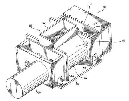
Referring now to FIGURE 3, one embodiment of a pulp flaker 300 according to
the present invention, is illustrated. The pulp flaker 300 includes a housing
302,.which is
designed to be in close tolerance with the rotors housed within. The housing
302
comprises two semicircular housing members 330, 332 spaced from each other to
provide
openings for an inlet and an outlet at top and bottom positions,
respec.tively: It is to be
appreciated that the use of directional language in this application, such as
top, bottom,
upper, lower, left, right, horizontal, vertical is with respect to the
figures. In practice, the
apparatus may be oriented differently from the orientations shown to the
figures. Cover
plates 334, 336 are placed on either side of the semicircular housing members.
The cover
plates may be provided with the necessary openings for rotor shafts,
supporting bearings,
drivers, gears, and/or one or more driver shafts. Further additional
supporting structure
may be added to the pulp flaker as required by the pulp flaker's location or
placement.
Rotors (minimally visible in FIGURE 3) are assemblies comprising at least a
shaft and a
plurality of fingers fixed to the shaft. The pulp flaker 300 includes an inlet
box 304
coupled with an opening in the housing to allow pulp to fall on the rotating
rotors inside.
The inlet box 304 is located at a central location to direct the pulp to the
rotors. A chute
(not shown) can be provided as a transition piece between the belt conveyor
204 and the
pulp flaker inlet box. An outlet (338 in FIGURE 4) is located on the underside
of the
pulp flaker 300 and coupled to an opening in the housing to allow the pulp to
be
-9-
CA 02480891 2004-09-07
discharged from the housing to any downstream equipment. The outlet can be
configured
to mate with the inlet of any suitable dryer so as to transfer the pulp flakes
produced by
the pulp flaker, to the dryer.'
The pulp flaker 300 includes a driver 306. The driver shaft (not shown) is
coupled directly or indirectly through gears to, at 'least one first rotor
within housing 302.
A second rotor can be coupled to an independent driver, or alternatively, can
be coupled
to the same driver 306 with or without a reduction or increase in gear ratio.
First and
second rotors are configured to rotate at a specified speed differential, and
in opposite
directions. Opposite directions means that one rotor turns clockwise and one
rotor turns
counterclockwise. At least one rotor is configured to rotate at a speed from
about
500 rpm to about 3600 rpm. This rotor is referred to as the "full speed
rotor." The speed
of the full speed rotor is dependent on the type of pulp, shape and size of
pulp bundles,
and processing times. The second rotor is configured to operate at a reduced
ratio that is
one-tenth to nine-tenths the speed of the full speed rotor. The rotor that
operates at a
reduced speed is referred to as the "off speed rotor." The off speed rotor may
additionally
function to clean the full speed rotor to allow uniform feed throughput. In
one
embodiment, the preferred speed of rotation for the second or off speed rotor
is about
one-third the speed of the full speed rotor. It is theorized that rotors
operating at about a
3 to 1 speed ratio optimally produce the pulp in the desired flake size range
suitable for a
dryer, such as ajet dryer.
Referring now to FIGURE 4, a cross sectional illustration of the pulp flaker
300
with one cover plate removed clearly shows first and second rotor
relationship, 308 and
310 respectively, and the semicircular housing members 330 and 332 that
enclose them.
As shown in FIGURE 4, rotor 308 and rotor 310 include a plurality of
fingers 312, attached to the respective shafts of rotors. The fingers on each
of the rotors
are uniformly distributed circumferentially around the perimeter of the rotor
shaft. For
ease of manufacture, a flat plate can be used to produce each set of eight
fingers.
Fingers 312 can be formed attached to a central hub 318 with an opening,
wherein the
hub 318 then can be press fitted on the shaft and fixed in place. Spacers
integral with the
hub, or as separate components, are provided between hubs on a shaft to
provide a finger
to finger space between adjacent sets of fingers. The space between fingers
allows the
fingers of the opposing rotor to pass in the space with a desired clearance on
either side.
-10-
CA 02480891 2004-09-07
The number of sets of fingers on any one shaft can be varied according to the
design
and/or capacity of the pulp flaker. Sets of fingers on any one rotor may be
fixed at the
same angle on the rotor or each set may be offset at an angle from the
adlacent sets.
When the two assembled rotors are mounted within the housing, an alternating
pattern of
fingers is produced, whereby fingers on one rotor are interspaced with the
fingers on the
second rotor. The interspaced finger configuration is more clearly shown in
FIGURE 6.
Various configurations of fingers are possible. Finger configuration is
designed to
impact the pulp in a manner to produce flakes in the desired size range.
Fingers on both
rotors include at least one leading edge 314, whereby upon rotation the
leading edge
passes in close proximity to the inner surface of one of the semicircular
housing
members 330 and 332. The clearance distance 316 between the leading edge of
fingers
and the semicircular housing is designed to produce pulp in the particulate
size desired,
typically in the "range of about one-sixteenth of an inch to about one-half of
an inch, on
average. The leading edge 314 of fingers 312 is not spaced so far apart from
the
semicircular housing, so as to merely roll or push the pulp around the housing
without
significant breaking up of the pulp. In one embodiment, the clearance distance
316
between the leading edge 314 and the housing is about one-eighth of an inch or
less.
In one embodiment of a pulp flaker finger 312, the finger is, symmetrical with
respect to an axis line extending along a radius line from the rotor center.
Two leading
edges are provided on each finger on either side of the axis line. A space is
provided
between the leading edges. The effect of this design is to double the number
of impacts,
while operating at a lower rpm. It is believed that increasing rpms beyond an
upper limit
will have a negative effect on the pulp. Too high an rpm will result in the
pulp fiber
integrity being compromised. At the same time, the rpm of the full speed rotor
is not so
low so as to cause unacceptably large pulp particulates leaving the flaker.
The rpm of the
full speed rotor is from about 500 rpm to about 3600 rpm.
An alternative design for a pulp flaker finger plate 400 .is illustrated in
FIGURE 7.
In this embodiment, there are 6 fingers compared to the 8 fingers of the
embodiment
shown in FIGURE 4. Furthermore, each of the fingers 402 has a single leading
edge 404.
The finger has a trailing edge 406 that has a greater clearance distance as it
passes by the
semicircular housing portion. It is believed the reduction in clearance
distance at the
trailing edge will avoid the effect of rolling and/or pushing the pulp along
the housing
-11-
CA 02480891 2004-09-07
without significant breakdown. Another feature of the pulp flaker finger of
FIGURE 7 is
the curved "scoop" design 408 of the finger edge heading in the direction of
rotation. The
scoop design is intended to scoop up the pulp in the spaces between fingers
and fling the
pulp towards the outer edges, where the leading edges will impact with the
pulp.
Referring back to FIGURE 4, as the rotors 308 and 310 rotate in opposite
directions, as indicated by the curved arrows, the leading edges of fingers of
one rotor
will pass nearest to the opposite rotor when the fingers are slightly at an
angle before
being horizontal. This is because the leading edges are offset from the center
axis on
each finger. As the rotors rotate, the fingers of one rotor pass interspaced
between the
fingers of the opposite rotor in the region between rotors. The clearance
distance (320 in
FIGURE 6) between the leading edge of the fingers of one rotor and the
opposite rotor
can be about the same as the distance between the leading edge of the fingers
and the
semicircular part of the housing. In one embodiment, the distance from the
leading edge
when the fingers pass the nearest point to the opposing rotor (i.e., the
fingers pass by the
spacers of the opposing rotor), is approximately one-eighth of an inch or
less. Note that
the leading edges are at the nearest point to the opposing rotor immediately
before the
finger reaches the horizontal position, when the longitudinal axis of the
finger is in the
line defined by the center points of the rotors.
Referring now to FIGIJRE 5, the two rotors 308, 310, are shown in isolation
from
the housing, thus showing the fingers both circumferentially and
longitudinally arranged
on each rotor. The intermeshing of the fingers of one rotor with the fingers
of the
opposing rotor as the fingers pass one another in the region between rotors is
clearly
apparent. The pulp feed is deposited from above in the region between rotors.
The pulp
is immediately diminished in size in the section between rotors, where the
fingers of one
rotor pass in close proximity to the fingers of the second rotor.
The longitudinal distance (324 in FIGURE 6) between the fingers of one rotor
and
the adjacent fingers of the opposite rotor, on either side, is about the same
as the
distance 320 between any leading edge as it passes the nearest point of the
opposing
rotor. The distance is also approximately the same distance as the clearance
distance 316
between the leading edge and the semicircular portion of the housing. In one
embodiment, the longitudinal distance between one finger of one rotor and the
adjacent
finger of the opposing rotor is approximately one-eighth of an inch or less.
Three
-12-
CA 02480891 2004-09-07
distances affecting finger design, and consequently pulp size, have been
described. These
three distances are: the longitudinal distance between the finger of one rotor
and the
adjacent finger of the opposing rotor as the fingers pass interspaced between
the region
between rotors (finger to finger distance), the distance between the leading
edge of a
finger as it passes to the nearest point of the opposing rotor (finger to
rotor distance), and
the distance of the leading edge of a finger to the semicircular portion of
the housing
(finger to housing distance). In one embodiment, the three distances are
approximately
the same to one another, the distance being approximately one-eighth of an
inch or less.
However, it is to be appreciated from a reading of this disclosure, each of
the distances
can be independently different to each other.
The selected clearance distance between the leading edges and the opposing
rotor,
the clearance distance between the fingers as they pass one another, and the
clearance
distance between the fingers as they pass the semicircular housing portion,
enables the
pulp to be processed by the flaker without damaging cellulose fibers or
jamming the
flaker. Additionally, the ends of the fingers have a flat spot 340 of specific
width, the
width being perpendicular to a radius line from the rotor. The pulp flaker
finger
embodiment of FIGURE 7 also includes a flat spot 410. It is believed that the
flat spots
of the fingers reduce the amount of material that gets pushed around the
housing and also
reduces the wear on the fingers.
Referring now to FIGURE 6, the top view of the rotors 308 and 310 shown in
isolation in FIGURE 5, is illustrated. As can be seen in FIGURE 6, the section
between
rotors 308 and 310 is configured to close tolerances to produce the required
pulp size
reduction. Not only is there a close tolerance distance between the leading
edges and the
housing, but there is also a close tolerance distance 324 between alternating
fingers 312
of rotor 308 and fingers 322 of rotor 310. The clearance distance 320 between
the
leading edge of fingers of rotor 310 to the opposing spacer 318 on rotor 308
is visible; as
is the clearance distance 324 between the fingers of rotor 310 and the fingers
of rotor 308.
As can be seen, the pulp entering the pulp flaker from above the rotating
fingers is
subjected to efficient impacting and shearing forces to reduce the incoming
pulp size to a
substantially uniform size in the range of about one-sixteenth to about one-
half of an
inch, or less, on average.
-13-
CA 02480891 2004-09-07
While the preferred embodiment of the invention has been illustrated and
described, it will be appreciated that various changes can be made therein
without
departing from the spirit and scope of the invention.
-1~-