Language selection

Search

Patent 2481003 Summary

Third-party information liability

Some of the information on this Web page has been provided by external sources. The Government of Canada is not responsible for the accuracy, reliability or currency of the information supplied by external sources. Users wishing to rely upon this information should consult directly with the source of the information. Content provided by external sources is not subject to official languages, privacy and accessibility requirements.

Claims and Abstract availability

Any discrepancies in the text and image of the Claims and Abstract are due to differing posting times. Text of the Claims and Abstract are posted:

  • At the time the application is open to public inspection;
  • At the time of issue of the patent (grant).
(12) Patent: (11) CA 2481003
(54) English Title: METHOD OF LOCALIZING A HOLE DRILLED WITH A ROCK DRILLING MACHINE
(54) French Title: PROCEDE DE LOCALISATION D'UN TROU FORE AVEC UNE MACHINE DE FORAGE DE ROCHES
Status: Deemed expired
Bibliographic Data
(51) International Patent Classification (IPC):
  • E21B 44/00 (2006.01)
  • E21D 20/00 (2006.01)
  • G06T 7/00 (2006.01)
(72) Inventors :
  • PLANESKOG, BERTIL (Sweden)
  • GUSTAVSSON, HANS (Sweden)
(73) Owners :
  • ATLAS COPCO ROCK DRILLS AB (Sweden)
(71) Applicants :
  • ATLAS COPCO ROCK DRILLS AB (Sweden)
(74) Agent: FETHERSTONHAUGH & CO.
(74) Associate agent:
(45) Issued: 2011-06-21
(86) PCT Filing Date: 2003-03-14
(87) Open to Public Inspection: 2003-10-16
Examination requested: 2008-03-10
Availability of licence: N/A
(25) Language of filing: English

Patent Cooperation Treaty (PCT): Yes
(86) PCT Filing Number: PCT/SE2003/000426
(87) International Publication Number: WO2003/085233
(85) National Entry: 2004-09-30

(30) Application Priority Data:
Application No. Country/Territory Date
0201014-8 Sweden 2002-04-04

Abstracts

English Abstract


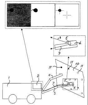
Apparatus and method for localizing a hole drilled with rock
drilling machine are provided. After creating a digital
picture, a distance between a boom and the drilled hole is
measured, the digital picture is stored, the stored picture
is transformed to a picture of black and white parts, the
transformed picture is scanned to find a black part with a
size corresponding to the drill hole and the position of the
drill hole mouth is determined. A higher degree of
automation at rock bolting, as well as drilling and bolting
with separate booms, can be achieved.


French Abstract

L'invention concerne une procédé de localisation d'un trou (11) foré au moyen d'une machine de forage de roches comprenant une flèche (3) disposée sur un engin de forage au voisinage du trou foré à l'aide d'un système de positionnement équipant la tour de forage, le procédé étant caractérisé en ce qu'une image numérique est créée au moyen d'un appareil photographique (5) disposé sur la flèche (5), la distance entre la flèche (3) et le trou foré (11) étant mesurée au moyen d'un compteur de distance (6), l'image numérique (fig. 3) étant stockée dans un ordinateur (2), cette image stockée étant transformée en une image contenant seulement des parties en noir et blanc (fig. 4), cette dernière image étant scannée afin de trouver une partie en noir dont la taille, dans un domaine de taille donné, correspond au trou foré, la position de la gueule du trou foré dans la roche étant déterminée à l'aide de la position de la partie en noir et de la distance mesurée.

Claims

Note: Claims are shown in the official language in which they were submitted.


3


CLAIMS:


1. Method of localizing a hole drilled with a rock
drilling machine comprising positioning a boom arranged on a
rock drilling rig near the drilled hole with the aid of a
positioning system arranged on the rock drilling rig, the
method comprising: creating a digital picture by means of a
camera arranged on the boom, measuring a distance between
the boom and the drilled hole by means of a distance meter,
storing the digital picture in a computer, transforming the
stored picture to a picture containing only black and white
parts, scanning the picture with only black and white parts
to find a black part with a size within a size interval
corresponding to the drilled hole and determining the
position of the drill hole mouth in the room with the aid of
the position of the black part and the measured distance.


2. An arrangement for localizing a hole drilled with
a rock drilling machine, said arrangement comprising:

a positioning system for positioning a boom
arranged on a carrier near the drilled hole;

a camera arranged on the boom and adapted to
create a digital picture;

a distance meter adapted to measure a distance
between the boom and the drilled hole;

means for storing the digital picture in a
computer;

means for transforming the stored picture to a
picture containing only black and white parts;


4


means for scanning the picture with only black and
white parts to find a black part with a size within a size
interval corresponding to the drilled hole; and

means for determining the position of the drill
hole mouth in the room with the aid of the position of the
black part and the measured distance.


3. The arrangement according to claim 2, wherein the
camera and the distance meter are arranged adjacent to each
other on the boom.


4. The arrangement according to claim 2 or 3, wherein
a second boom is arranged on the carrier.


5. The arrangement according to claim 4, wherein one
of the booms carries a unit for rock bolting.


6. The arrangement according to claim 5, wherein the
other boom carries a unit for rock drilling.


7. A rig comprising a carrier and a boom, and an
arrangement for localizing a hole according to any one of
claims 2 to 6.

Description

Note: Descriptions are shown in the official language in which they were submitted.


CA 02481003 2008-03-10
29312-51

1
Method of localizing a hole drilled with a rock drilling
machine

The present invention relates to a method of
localizing a hole drilled with a rock drilling machine, e.g.
in connection with rock bolting.

According to a previously known method for rock
bolting with rig a feed beam on a rock drilling rig is
applied steadily against the rock after which a hole is
drilled with a rock drilling machine. After that the rock
drilling machine is moved away and a device for bolting is
moved in place for entering a rock bolt into the drilled
hole. Other steps can also be there depending on type of
rock bolt. In order to make it practically possible to move
the rock bolt into the hole the steady application against

the rock must be kept during the sequence of drilling and
bolt setting. The reason for this is that large masses are
moving when the feed beam is positioned. Since the rock
drilling rig has several links between the carrier and the
application point against the rock sufficient precision in

the alignment against the drilled hole is not achieved if
the rock drilling rig's own alignment system is used.
Neither is it practically possible to split drilling and
bolting between different boom units on the rock drilling
rig.

The present invention aims at achieving a method
which makes possible a high degree of automation at rock
bolting and also drilling and bolting with separate booms
for the units used for drilling and bolting.

According to one aspect of the invention, there is
provided method of localizing a hole drilled with a rock
drilling machine comprising positioning a boom arranged on a


= CA 02481003 2008-03-10
29312-51

la
rock drilling rig near the drilled hole with the aid of a
positioning system arranged on the rock drilling rig, the
method comprising: creating a digital picture by means of a
camera arranged on the boom, measuring a distance between

the boom and the drilled hole by means of a distance meter,
storing the digital picture in a computer, transforming the
stored picture to a picture containing only black and white
parts, scanning the picture with only black and white parts
to find a black part with a size within a size interval
corresponding to the drilled hole and determining the
position of the drill hole mouth in the room with the aid of
the position of the black part and the measured distance.

According to another aspect of the invention,
there is provided an arrangement for localizing a hole
drilled with a rock drilling machine, said arrangement

comprising: a positioning system for positioning a boom
arranged on a carrier near the drilled hole; a camera
arranged on the boom and adapted to create a digital
picture; a distance meter adapted to measure a distance

between the boom and the drilled hole; means for storing the
digital picture in a computer; means for transforming the
stored picture to a picture containing only black and white
parts; means for scanning the picture with only black and
white parts to find a black part with a size within a size
interval corresponding to the drilled hole; and means for
determining the position of the drill hole mouth in the room
with the aid of the position of the black part and the
measured distance.

According to still another aspect of the

invention, there is provided a rig comprising a carrier and
a boom, and an arrangement for localizing a hole as
described above.


CA 02481003 2008-03-10
29312-51

lb
An embodiment of the invention is described below
with reference to the accompanying drawing in which Fig 1
shows a rock drilling rig. Fig 2 shows on a larger scale a
part of the rock drilling rig according to Fig 1. Figs 3-5

show pictures of a rock surface with different degrees of
image processing.

The rock drilling rig shown in the drawing
comprises a carrier 1 on which, in the shown example, two
booms 3 and 4 are arranged. The rock drilling rig is

provided with a computer 2. On boom 3 a digital camera 5
and a distance meter 6 are arranged. These are connected
with the computer 2 by means of conductors 7 or by means of
wireless connections 8 and 9. The distance meter suitably
works with ultrasonics. Drilling is done in


CA 02481003 2004-09-30
WO 03/085233 PCT/SE03/00426
2
a rock surface 10 which, in fig 1, is shown by. means of black holes 11. In
the shown
example drilling is performed by means of a rock drilling machine arranged on
boom 4.
The drilled hole is then localized by means of the digital camera 5, the
distance meter 6 and
the computer 2. One can also have rock drilling machine, digital camera and
distance meter
on the same boom. It is thereby not necessary to hold the boom steadily
against the rock
surface 10 between drilling and the subsequent localization of the drilled
hole.

The method according to'the invention works in the following way. First one or
more holes
11 are rilled in the rock surface 10 by means of a rock drilling machine
mounted on one of
the booms 3 or 4. In order to localize a drilled hole boom 3 is aligned with
the aid of the
positioning system of the drill rig so that the digital camera 5 and the
distance meter 6 are
near the hole to be localized. A picture of the rock surface 10 is stored in
the computer, fig
3. Furthermore, the measured distance is stored in the computer. The stored
picture, fig 3,
contains a black hole with the rest in different shades of gray. With the aid
of a program
stored in the computer a new picture, fig 4, is created which only contains
black and white
spots. This picture is filtered so that only black parts within a
predetermined size range
remain, fig 5. The picture matrix is scanned to determine the outer
coordinates of the black
part. This area is compared with the size of a drilled hole though calculating
the real size of
the picture matrix with the aid of the outer coordinates and the measured
distance. When an
area corresponding to the size and form of a drilled hole, known size, has
been found the
coordinates of the centre of the area is determined. After that a boom can be
aligned against
the hole with the aid of the coordinates, e.g. for inserting a rock bolt.

Representative Drawing
A single figure which represents the drawing illustrating the invention.
Administrative Status

For a clearer understanding of the status of the application/patent presented on this page, the site Disclaimer , as well as the definitions for Patent , Administrative Status , Maintenance Fee  and Payment History  should be consulted.

Administrative Status

Title Date
Forecasted Issue Date 2011-06-21
(86) PCT Filing Date 2003-03-14
(87) PCT Publication Date 2003-10-16
(85) National Entry 2004-09-30
Examination Requested 2008-03-10
(45) Issued 2011-06-21
Deemed Expired 2019-03-14

Abandonment History

There is no abandonment history.

Payment History

Fee Type Anniversary Year Due Date Amount Paid Paid Date
Registration of a document - section 124 $100.00 2004-09-30
Application Fee $400.00 2004-09-30
Maintenance Fee - Application - New Act 2 2005-03-14 $100.00 2005-02-08
Maintenance Fee - Application - New Act 3 2006-03-14 $100.00 2006-02-07
Maintenance Fee - Application - New Act 4 2007-03-14 $100.00 2007-02-07
Maintenance Fee - Application - New Act 5 2008-03-14 $200.00 2008-02-06
Request for Examination $800.00 2008-03-10
Maintenance Fee - Application - New Act 6 2009-03-16 $200.00 2009-02-09
Maintenance Fee - Application - New Act 7 2010-03-15 $200.00 2010-02-09
Maintenance Fee - Application - New Act 8 2011-03-14 $200.00 2011-02-07
Final Fee $300.00 2011-04-04
Maintenance Fee - Patent - New Act 9 2012-03-14 $200.00 2012-02-08
Maintenance Fee - Patent - New Act 10 2013-03-14 $250.00 2013-02-13
Maintenance Fee - Patent - New Act 11 2014-03-14 $250.00 2014-03-10
Maintenance Fee - Patent - New Act 12 2015-03-16 $250.00 2015-03-09
Maintenance Fee - Patent - New Act 13 2016-03-14 $250.00 2016-03-07
Maintenance Fee - Patent - New Act 14 2017-03-14 $250.00 2017-03-13
Owners on Record

Note: Records showing the ownership history in alphabetical order.

Current Owners on Record
ATLAS COPCO ROCK DRILLS AB
Past Owners on Record
GUSTAVSSON, HANS
PLANESKOG, BERTIL
Past Owners that do not appear in the "Owners on Record" listing will appear in other documentation within the application.
Documents

To view selected files, please enter reCAPTCHA code :


To view images, click a link in the Document Description column. To download the documents, select one or more checkboxes in the first column and then click the "Download Selected in PDF format (Zip Archive)" or the "Download Selected as Single PDF" button.

List of published and non-published patent-specific documents on the CPD .

If you have any difficulty accessing content, you can call the Client Service Centre at 1-866-997-1936 or send them an e-mail at CIPO Client Service Centre.


Document
Description 
Date
(yyyy-mm-dd) 
Number of pages   Size of Image (KB) 
Abstract 2004-09-30 2 88
Claims 2004-09-30 1 21
Drawings 2004-09-30 1 38
Description 2004-09-30 2 92
Representative Drawing 2004-12-09 1 27
Cover Page 2004-12-09 2 65
Abstract 2008-03-10 1 15
Description 2008-03-10 4 144
Claims 2008-03-10 2 56
Claims 2010-06-18 2 55
Cover Page 2011-05-20 1 58
PCT 2004-09-30 7 276
Assignment 2004-09-30 3 126
Prosecution-Amendment 2008-03-10 8 238
Prosecution-Amendment 2009-12-18 3 75
Prosecution-Amendment 2010-06-18 4 163
Correspondence 2011-04-04 2 61