Note: Descriptions are shown in the official language in which they were submitted.
CA 02481075 2004-10-O1
WO 03/088005 PCT/US03/12184
SYSTEMS AND METHODS FOR PERFORMING TRANSACTIONS AT
A POINT OF-SALE
CROSS-REFERENCES TO RELATED APPLICATIONS
S [Ol] This application is a continuation-in-part application of U.S. Pat.
App. No.
09/634,901, entitled "POINT OF SALE PAYMENT SYSTEM," filed August 9, 2000 by
Randy J. Templeton et al., which is a nonprovisional of U.S. Prov. App. No.
60/147,899,
entitled "INTEGRATED POINT OF SALE DEVICE," filed August 9, 1999 by Randy
Templeton et al., the entire disclosures of both are herein incorporated by
reference for all
purposes.
[02] Further, this application is related to U.S. Pat. App. No. 10/116,733
(Attorney Docket
No. 20375-002412), entitled "Systems and Methods for Deploying a Point-of Sale
System",U.S. Pat. App. No. 10/116,686 (Attorney Docket No. 20375-002413),
entitled
"Systems and Methods for Utilizing a Point-of Sale System", and U.S. Pat. App.
No.
10/116,735 (Attorney Docket No. 20375-002414), entitled "Systems and Methods
for
Configuring a Point-of Sale System", all of which are incorporated herein by
reference for all
purposes and filed on a date even herewith.
BACKGROUND OF THE INVENTION
[03] This invention relates to point-of sale devices and to point-of sale
transactions. More
particularly, this invention relates to an integrated point-of sale device
capable of facilitating
transactions associated with one or more transaction systems.
[04] In the sale of goods by a merchant to a customer, point-of sale devices
are used by the
merchant to complete a transaction. For example, a common cash register can be
used to
tally the cost of items purchased, accept cash payments, and return the proper
amount of
change. In some cases, such a register can be used in conjunction with a
credit card reader.
More particularly, the merchant can ring up a total amount due on the
register, pass the credit
card through a card reader to debit the customer account, and in turn the
register recognizes
the payment by credit card. While devices for completing such transactions
exist, the
functionality of such devices is quite limited. Furthermore, such devices are
typically limited
to accessing records maintained by a merchant. Thus, for example, it can be
impossible for a
CA 02481075 2004-10-O1
WO 03/088005 PCT/US03/12184
merchant to determine if a credit card offered for payment is a stolen card.
In some cases,
obtaining additional functionality to, for example, determine if a credit card
is stolen, can be
achieved by installing equipment in addition to the cash register. This
additional equipment
typically must be individually installed, configured and maintained. Such an
approach is
costly and inefficient.
[OS] Furthermore, such an approach of using stand alone devices requires a
merchant to
become the interface between each of the devices which requires additional,
costly training.
Yet further, a number of functions useful to both merchants and customers
cannot be
facilitated using systems and methods known in the current art.
[06] For the foregoing reasons, there is a need for a point-of sale payment
terminal and
methods of using such that overcome the limitations of the current art. Hence,
among a
number of other advantages apparent from the following description, the
present invention
provides systems and methods for addressing the aforementioned limitations of
the current
art.
BRIEF SUMMARY OF THE INVENTION
[07] A point-of sale device useful in relation to a variety of circumstances
and/or
utilization methods. Various implementations of such point-of sale devices are
disclosed
herein. For example, one particular point-of sale device includes a base unit
adapted for
performing merchant functions and a peripheral unit adapted to perform
customer functions.
The base unit can include a base unit housing with a processor disposed
therein and capable
of supporting a variety of transaction types.
[08] As will be appreciated by reading the detailed description, such point-of
sale devices
can be configured in a variety of ways and incorporate a variety of different
components.
Further, such components can be integrated into a single device, into a base
unit and
peripheral unit, or into a device modifiable with add-in circuit cards and/or
plug-in
components.
[09] In one particular embodiment of the present invention, the point-of sale
device
includes a base unit adapted for performing merchant functions at a point-of
sale. The base
unit includes a base unit housing and a processor therein. The processor is
configured to
process a plurality of transaction types, wherein one of the plurality of
transaction types is a
check acceptance transaction. The point-of sale device further includes a
peripheral unit
adapted to perform customer functions at a point-of sale and in communication
with the base
2
CA 02481075 2004-10-O1
WO 03/088005 PCT/US03/12184
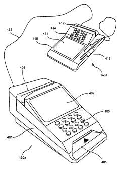
unit. In various embodiments, the peripheral unit is tethered to the base unit
by a physical
connection, while in other embodiments, the peripheral unit is in
communication with the
base unit via a wireless connection. In some cases, the base unit can include
a docking
station and the peripheral unit is adapted for docking within the docking
station.
S [10] Various other embodiments include a document slot within the base unit
housing for
accepting documents. Further, embodiments can include a magnetic magnetic-ink
character
recognition reader incorporated in the base unit, positioned with respect to
the document slot,
and adapted to read a string of magnetic-ink characters on the document when
the document
is inserted within the document slot. Yet further, the base unit can include a
document
imager positioned with respect to the document slot and adapted to capture an
image of the
document when the document is inserted within the document slot. Additionally,
some
embodiments include one or more printers configured to print on a document
received within
the document slot. Such printers can be of different types including roll
printers and slip
printers. In some embodiments, a combination of the aforementioned components
are
incorporated within the point-of sale device. In such embodiments, printers
and/or document
imagers can share a common paper transport mechanism.
[ll] In particular embodiments, point-of sale devices include one or more
biometrics
devices. Such biometrics devices can be deployed in either or both of a
peripheral and base
unit. Such biometrics devices can be finger-print devices, retinal devices,
voice
identification, face recognition, and the like. In some cases, the biometrics
devices) are used
to validate access to the point-of sale device.
[12] In various embodiments, the point-of sale device includes a magnetic
stripe writer. In
various cases, the magnetic stripe writer is associated with a card issuer for
distributing one
or more types of stored value cards. In some cases, such stored value cards
are gift
certificates for a retailer unrelated to the point-of sale device. In
particular instances, a point-
of sale device in accordance with the present invention can also print such
gift certificates to
be provided to a consumer interacting with the point-of sale device.
Furthermore, in some
instances various point-of sale devices in accordance with the present
invention can redeem
such gift certificates. The redemption can include inserting the gift
certificate into the point-
of sale device and reading it with a document imager. The image can be
analyzed to
determine the veracity and value of the gift certificate, with the value
thereof being
exchanged for related goods or services. In other cases, such a card issuer is
apart from any
magnetic stripe writer. Stored value cards used in relation to the point-of
sale device can
include phone cards, gift cards, and the like.
CA 02481075 2004-10-O1
WO 03/088005 PCT/US03/12184
[13] In some embodiments, the point-of sale device includes a modem located
within the
base unit housing and in communication with a processor. In other embodiments,
communication with the point-of sale device is provided via an external
communications
interface in communication with the processor. In particular embodiments, the
processor is
S further configured to receive and process Internet communications over the
external
communications interface.
[14] In another embodiment of the present invention, the point-of sale device
includes a
housing with an external communications interface located thereon. Further,
the point-of
sale device includes a processor disposed within the housing and in
communication with the
external communications interface. Such a processor can be configured to
process a plurality
of transaction types at a point-of sale and receive and process Internet
communications over
the external communications interface.
[15] In various embodiments, the point-of sale device includes a display and a
keyboard
on the housing, both in communication with the processor. In other
embodiments, the point-
of sale device includes a document slot adapted for receiving a document and a
magnetic-ink
character recognition device positioned with respect to the document slot and
adapted read a
string of magnetic-ink characters on a document when the document is inserted
within the
document slot.
[16] In some cases, the point-of sale device further includes a peripheral
unit interface
located on the housing and in communication with the processor. The peripheral
unit
interface can be configured to provide communication with a peripheral unit
adapted to
perform customer functions.
(17] In another embodiment, the point-of sale device includes a base unit
adapted for
performing merchant functions at a point-of sale and a peripheral unit in
communication with
the base unit and adapted for docking with the base unit. The base unit
includes a base unit
housing with a document slot adapted for receiving a document, a processor
disposed within
the base unit housing and configured to process a plurality of transaction
types, and a
magnetic-ink character recognition device positioned with respect to the
document slot and
adapted to read a string of magnetic-ink characters on the document when the
document is
inserted within the document slot. The base unit further includes a docking
station integral
with the base unit housing. The peripheral unit includes a peripheral unit
housing with a
display unit thereon.
[18] Yet a further embodiment is a method for processing a transaction. The
method
includes capturing information related to the transaction at a point-of sale
with a peripheral
4
CA 02481075 2004-10-O1
WO 03/088005 PCT/US03/12184
unit. The information is requisite for at least one of a plurality of
predefined authorized
transaction types that includes check processing. The information is
transmitted to a base
unit positioned locally with respect to the peripheral unit and the
transaction is processed in
accordance with the at least one. predefined authorized transaction types
using the transmitted
information. In some aspects, transmitting the information to the base unit is
performed
wirelessly, while in other aspects, transmitting is done via a wired
connection or a docking
station.
[19] In some aspects, capturing information related to the transaction
includes
electronically capturing a signature of a customer via a touch-screen display.
In other
aspects, capturing information related to the transaction includes capturing
numeric data from
a keypad associated with the peripheral unit. In yet other aspects, capturing
information
related to the transaction includes reading a magnetic stripe with a magnetic
stripe card reader
associated with the peripheral unit. In yet further aspects, capturing
information related to the
transaction includes reading a smart card with a smart-card reader associated
with the
peripheral unit.
[20] In various aspects, the method further includes collection of additional
information
related to the transaction via the base unit. Such additional information is
also requisite for
the at least one predefined authorized transaction types. In some aspects,
collecting the
additional information includes reading a string of magnetic-ink characters
from a document
with a magnetic-ink character recognition reader associated with the base
unit.
[21] The summary provides only a general outline of the embodiments according
to the
present invention. Many other objects, features and advantages of the present
invention will
become more fully apparent from the following detailed description, the
appended claims and
the accompanying drawings.
BRIEF DESCRIPTION OF THE DRAWINGS
[22] A further understanding of the nature and advantages of the present
invention may be
realized by reference to the figures which are described in remaining portions
of the
specification. In the figures, like reference numerals are used throughout
several figures to
refer to similar components. In some instances, a sub-label consisting of a
lower case letter is
associated with a reference numeral to denote one of multiple similar
components. When
reference is made to a reference numeral without specification to an existing
sub-label, it is
intended to refer to all such multiple similar components.
CA 02481075 2004-10-O1
WO 03/088005 PCT/US03/12184
[23] Fig. 1 illustrates a multi-function transfer system in accordance with an
embodiment
of the present invention;
[24] Fig. 2 is a logical block diagram of a point-of sale device in accordance
with an
embodiment of the present invention;
[25] Fig. 3 is a schematic diagram of components included in one embodiment of
a point-
of sale device in accordance with the present invention;
[26] Figs. 4A-4F show perspective views of mechanical layouts of point-of sale
devices in
accordance with various embodiments of the present invention;
[27] Fig. SA illustrates a stored value card system operating as on of the
function central
controls of Fig. 1 and in accordance with some embodiments of the present
invention;
[28] Fig. SB is a flow diagram illustrating one method of accessing the stored
value card
system of Fig. SA using a point-of sale device in accordance with an
embodiment of the
present invention;
[29] Fig. SC illustrates a phone card system operating as on of the function
central controls
of Fig. 1 and in accordance with an embodiment of the present invention;
[30] Fig. SD is a flow diagram illustrating one method of enabling a point-of
sale device to
access the phone card system of Fig. SC in accordance with embodiments of the
present
invention;
[31] Fig. SE is a flow diagram illustrating a method for issuing and using
phone cards in
accordance with the present invention;
[32] Fig. 6 illustrates an embodiment of a value transfer system used in
relation to a point-
of sale device in accordance with embodiments of the present invention;
[33] Fig. 7 illustrates a function central control, associated with the value
transfer system
of Fig. 6, and in accordance with an embodiment of the present invention;
[34] Fig. 8 illustrates an encashment system deployed in relation to point-of
sale devices
and in accordance with an embodiment of the present invention;
[35] Fig. 9 illustrates a method in accordance with the present invention for
utilizing the
encashment system of Fig. 8 in relation to a point-of sale device;
[36] Fig. 10 illustrates a loyalty system operated in relation to a point-of
sale device in
accordance with an embodiment of the present invention;
[37] Fig. 11 is a flow diagram of the loyalty system of Fig. 10;
[38] Fig. 12A is a block diagram of a loyalty host as illustrated in Fig. 10;
[39] Fig. 12B is a functional diagram of the loyalty system of Fig. 10;
6
CA 02481075 2004-10-O1
WO 03/088005 PCT/US03/12184
[40] Figs. 13A-13D are flow diagrams of methods used in relation to the
loyalty system of
Fig. 10;
[41] Fig. 14 illustrates a check acceptance system operated in relation to a
point-of sale
device and in accordance with embodiments of the present invention;
[42] Fig. 15A illustrates a method in accordance with embodiments of the
present
invention for enabling access to the check acceptance system of Fig. 14 via a
point-of sale
device; and
[43] Fig. 15B illustrates operation of the check acceptance system of Fig. 14
in relation
with a point-of sale device, and in accordance with embodiments of the present
invention.
DETAILED DESCRIPTION OF THE INVENTION
I. Overview
[44] Various embodiments of the present invention are directed to a common
Point-of Sale
("POS") system configured to facilitate a variety of transaction types to
customers in a
convenient fashion. In some embodiments, the POS system comprises an
integrated POS
device while, in other embodiments, the POS system comprises a base unit and a
peripheral
unit. In such embodiments, certain features of the system are distributed
between a POS base
terminal and a POS peripheral terminal instead of being common to the
integrated device as
they are in those embodiments that use the integrated device.
[45] For example, components that may form part of the POS base terminal
include, but
are not limited to, a display, a keypad, a magnetic-stripe card reader, an
integrated roll
printer, an integrated slip printer, other types of printers, a magnetic-ink
character-recognition
("MICR") reader, a smart card reader, a document imager, connection and/or
communication
ports including Ethernet and USB communications, a modem, a microphone, a
speaker, a
touch-screen, a card issuer, an operating system, software, and circuit cards,
such as, sound
cards and/or I/O cards. In addition, interfaces may be provided for connection
with an
external monitor and/or keyboard. In different embodiments, the POS base
terminal
comprises all or some of such components. Such components permit the POS base
terminal
to be used by merchants to process multiple types of electronic-payment and
other
transactions, including credit transactions, debit transactions, check
transactions, money-
transfer transactions, money-order sales, bill payments, management of
customer-loyalty
7
CA 02481075 2004-10-O1
WO 03/088005 PCT/US03/12184
programs, issuance of coupons, acceptance of coupons, issuance of stored value
cards, fraud
detection associated with a variety of transaction types, and other such
functions.
[46] In particular embodiments, a bi-directional printer is included with the
POS device.
Such a bi-directional printer is capable of printing from left to right, from
right to left, and
vertically in one or both directions. Such a bi-directional printing
capability is useful for a
number of reasons. For example, such a printer can be used to frank a check.
When the
check is inserted in the slip printer and/or imager vertically, it is scanned
by the imager and
MICR reader for content. Such a process can be accomplished once on insertion
of the check
into POS device 130 and then again on the exit. Then, in some cases, the slip
printer prints
the pay line of the check, which can include a 90 degree rotation of the print
head. Once the
printing is complete, the check is turned over by the clerk and placed back in
slip printer
and/or imager for franking the back of the check. Such franking of the back of
the check can
include receipt information, such as, a merchant number, a store name, a time
stamp, a dollar
amount, and the like.
[47] Further, in some embodiments, the imager is capable of bi-directional
imaging
including up and down vertically and both directions horizontally. In one
particular
embodiment, such bi-directional imaging is accomplished using two imaging
sources, one for
horizontal and one for vertical.
[48] Components that may form part of the POS peripheral terminal can include,
but are
not limited to, a display, an electronic signature capture, a magnetic-stripe
card reader, a
smart card reader/writer, a PIN pad, and a security system. In different
embodiments, the
POS peripheral terminal comprises all or some of such components. Such
components
permit the POS peripheral terminal to be an interactive tool that allows
customers to select
their preferred transaction methods, view line-item details of transactions,
and be provided
with web-enabled electronic services, such as advertising (e.g., textual,
graphics and/or video
advertising) and coupons. As will be recognized from the discussion below, the
POS
peripheral terminal can include components in addition to those previously
listed, only a
subset of those previously listed, or some combination of a subset of the
previously listed
components and additional components.
[49] Some embodiments of the present invention include systems and methods for
using
POS devices in relation to various central systems. Such central systems can
include
electronic-payment systems, money transfer systems, credit transaction
systems, check
transaction and verification systems, money order sales, stored value systems,
management
systems associated with customer-loyalty programs, coupon processing systems,
fraud
8
CA 02481075 2004-10-O1
WO 03/088005 PCT/US03/12184
detection systems, lottery ticket sales systems, and a number of other such
transaction
systems.
[50] In particular embodiments, a common POS device is used to access a
variety of
transaction systems. Further, in some of the embodiments, the transaction
systems are
developed and maintained by parties apart from those developing and
maintaining the POS
devices. In some embodiments, the POS devices include a number of components
that can be
individually enabled and disabled by the transaction systems depending upon,
for example, a
particular merchant's affiliation with various transaction systems.
[51] Some embodiments include interaction of a customer with one or more
transaction
systems during an interaction with a POS device. In some instances,
transactions initiated by
the customer and/or the merchant on behalf of the customer are consummated
without
requiring the customer or merchant to indicate the transaction system which is
selected to
process the transaction. Further, the customer may initiate a single
transaction requiring the
involvement of multiple transaction systems, in which case the POS device
automatically
selects the proper transaction systems and subsequently facilitates completion
of the desired
transaction.
II. Exemplary Systems
[52] Refernng to Fig. 1, a mufti-function transfer system 100 in accordance
with an
embodiment of the present invention is illustrated. Transfer system 100
includes a POS
device 130 in communication with one or more function central controls 110 via
a
communication network 120. Further, POS device 130 is communicably coupled to
POS
peripheral 140. As will be evident from the proceeding discussion, transfer
system 100 can
include any number of POS devices 130, POS peripherals 140, and/or function
central
controls 110 in accordance with the various embodiments of the present
invention.
[53] Communication network 120 can be any network capable of transmitting and
receiving information in relation to POS device 130. For example,
communication network
120 can comprise a TCP/IP compliant virtual private network ("VPN"), the
Internet, a local
area network ("LAN"), a wide area network ("WAN"), a telephone network, a
cellular
telephone network, an optical network, a wireless network, or any other
similar
communication network. In particular embodiments, transaction network 120
provides
message based communications between POS devices 130 and function central
controls 110.
9
CA 02481075 2004-10-O1
WO 03/088005 PCT/US03/12184
[54] In some embodiments, communication network 120 is a combination of a
variety of
network types. For example, in one embodiment, communication network comprises
the
Internet for communicating between POS device 130 and function central control
110a, a
Virtual Private Network ("VPN") for communicating between POS device 130 and
function
central control 110b, and a dial-up network for communicating between POS
device 130 and
function central control 1 l Oc. In light of this document, one of ordinary
skill in the art will
recognize a number of other network types and/or combinations thereof that are
capable of
facilitating communications between POS device 130 and various function
central controls
110.
[55] Each of function central controls 110 can be any system capable of
processing
transactions effectuated in relation to POS devices 130. For example, function
central
controls 110 can be a money or value transfer system, a fraud detection
system, a bad check
detection system, a phone or stored value card sales system, a bill payment
system, a bill
presentation system, a check acceptance system, a payroll system, a check
acceptance system,
and the like. In one particular embodiment of the present invention, transfer
system 100
includes more than twenty-thousand POS devices 130 with associated POS
peripherals 140,
and four function central controls 110. The function central controls 110 are
a money
transfer system, a fraud detection system, a phone card system, and a check
acceptance
system. Upon reading this document, one of ordinary skill in the art will
recognize many
types of function central controls useful in relation to the present
invention. Similarly, one of
ordinary skill in the art will recognize many possible combinations of such
function central
controls 110 deployed in relation to POS devices 130 and POS peripherals 140
in accordance
with the present invention.
[56] POS device 130 is an integration of two or more components for
facilitating customer
access to one or more function central controls 110. In some embodiments, POS
device 130
is an intelligent, counter top, merchant activated POS device targeted for use
in a variety of
retail environments. Some of the retail environments include capability to
transfer money,
consummate retail purchases; provide stored value cards including, but not
limited to, phone
cards and/or gift cards; perform fraud detection and surveillance; and the
like. In some
embodiments, POS device 130 operates as a single self contained device, while
in other
embodiments, POS device 130 operates in conjunction with one or more POS
peripherals
140.
[57] In some embodiments, POS peripheral 140 is a secure device which can
interface with
POS device 130, a Personal Computer ("PC"), an Electronic Cash Register
("ECR"), a
CA 02481075 2004-10-O1
WO 03/088005 PCT/US03/12184
Personal Digital Assistant ("PDA"), or other such devices. POS peripheral 140
can provide
functionality which is used by a consumer in a retail environment, such as
Personal
Identification Number ("PIN") entry, clear text entry, signature capture, and
the like. In
various embodiments, POS peripheral 140 can be used as a stand alone unit
capable of
operation apart from POS device 130 or other such base devices.
[58] Either separate or in conjunction, POS peripheral 140 and POS device 130
can
support a variety of functions together with a range of transactional services
offered through a
retailer maintaining POS device 130 and/or POS peripheral 140. Such
transactional services
can include, but are not limited to, money transfers, money orders, and/or
checking and check
guarantee services, and the like. In addition, the transactional services can
be provided by
one or more third party suppliers maintaining function central controls 110
accessible via
POS device 130 and/or POS peripheral 140. For example, money orders may be
requested
and printed by POS device 130 and/or POS peripheral 140 through access to a
first supplier's
transaction system (e.g., function central control 110), while check guarantee
services are
1 S provided by POS device 130 and/or POS peripheral 140 through access to a
second supplier's
transaction system (e.g., function central control 110).
[59] In some embodiments, POS peripheral 140 provides the identical
functionality
provided by POS device 130, albeit in a form accessible to a customer. Thus,
for example,
POS device 130 may be tailored for operation by a merchant, while the same
functionality is
implemented in POS peripheral 140 and tailored for operation by a customer. In
particular
embodiments, POS device 130 is mounted near a cash register at a check out
stand in a retail
outlet, while POS peripheral 140 is mounted on the check out stand and
accessible to a
customer. In this way, both the merchant and the customer can interact with
similar devices
to effectuate a transaction.
[60] In other embodiments, POS device 130 includes a number of components
while POS
peripheral 140 includes only a subset of such components. Thus, for example, a
customer is
capable of effectuating a limited number of transactions, or only a portion of
other
transactions via POS peripheral 140, whereas the merchant is capable of
effectuating all
transactions via POS device 130.
[61] In yet other embodiments, POS device 130 includes some components and POS
peripheral 140 includes a complimentary set of components. Thus, for example,
functions
useful for gathering information from a customer in relation to a transaction
are deployed as
part of POS peripheral 140, while components used by a merchant in relation to
a transaction
are deployed as part of POS device 130.
11
CA 02481075 2004-10-O1
WO 03/088005 PCT/US03/12184
[62] In some embodiments, POS peripheral 140 is communicably coupled to POS
device
130 via a cable 135. In other embodiments, POS peripheral 140 is communicably
coupled to
POS device 130 via a Radio Frequency ("RF") or line-of sight connection. While
the
preceding discussion identifies a variety of interconnects between POS device
130 and POS
peripheral 140, one of ordinary skill in the art will recognize a number of
other types of
interconnection capable of communicably coupling POS device 130 to POS
peripheral 140.
Furthermore, it should be recognized that more than one POS peripheral 140 can
be
associated with a single POS device 130. Alternatively, in some embodiments,
POS device
130 is implemented without an associated POS peripheral 140.
A. Functional Hardware
[63] Referring now to Fig. 2, a logical block diagram of one embodiment of POS
device
130 and POS peripheral 140 is illustrated. POS device 130 includes a Central
Processing
Unit ("CPU") 218 electrically coupled to a memory 214, a timer 212, a
component controller
220, and a function control matrix 216. Further, CPU 218 is communicably
coupled to a
display 210 via a graphics controller (not shown).
[64] Component controller 220 provides an interface to the variety of
components
associated with POS device 130 including a peripheral controller 250 that
controls access to
POS peripheral 140. More particularly, component controller 220 provides an
interface to a
card issuer 226, a network interface 228, an imager interface 230, a printer
interface 232, and
a Magnetic-Ink Character-Recognition ("MICR") interface 234. In addition,
component
controller 220 provides an interface to an Input/output ("I/O") interface 240
that in turn
provides access to and from a variety of I/O interfaces. Specifically, I/O
interface 240
provides for access via a keyboard interface 242, a magnetic reader interface
244, an
electronic reader interface 246, a biometrics interface 247, a Radio Frequency
("RF")
interface 227, a display reader interface 248, and an audio interface 249.
[65] Peripheral controller 250 provides for control of POS peripheral 140
under direction
of CPU 218 and component controller 220. More particularly, peripheral
controller 250
provides for access to a display 252, an imager interface 254, a printer
interface 256, and
access to and from an I/O interface 260. I/O interface 260 provides access to
an audio
interface 267, a biometrics interface 265, a keyboard reader interface 266, an
electronic
reader interface 264, a magnetic reader interface 268, and a display reader
interface 262.
12
CA 02481075 2004-10-O1
WO 03/088005 PCT/US03/12184
[66] CPU 218 can be any microprocessor capable of controlling the various
functions of
POS device 130 described herein. In some embodiments, CPU 218 is a thirty-two
bit
Reduced Instruction Set Computer ("RISC") processor. In one particular
embodiment, CPU
218 is a Motorola 68302 processor. In other embodiments, CPU 218 is a pair of
32-bit
processors one tasked to control the various components associated with POS
device 130 and
POS peripheral 140, and the other processor tasked with operating the various
software
applications executed in relation to POS device 130 and POS peripheral 140. In
some
embodiments, various of the blocks illustrated in Fig. 2 are implemented
within CPU 218,
while others of the blocks are implemented in logic apart from CPU 218. One
particular
embodiment of POS device 130 and POS peripheral 140 is discussed below with
reference to
Fig. 3, where the division between CPU 218 and logic implementing other
functions is more
fully described.
[67] Display 210 can be any type of display capable of presenting information
relevant to a
transaction to a user. For example, in some embodiments, display 210 is a
backlit graphic
Liquid Crystal Display ("LCD") of the chip on glass type, having eight lines
by twenty
characters, or one-hundred, twenty-eight by sixty-four pixels. Such a display
can be either
color or monochromatic. In some embodiments, the display is a Film Compensated
Super
Twisted Nematic ("FTSN") LCD. In one particular embodiment, display 210 is a
touch-
screen, one-quarter VGA monochrome display with 16 levels of gray scale. In
such an
embodiment, display reader interface 248 provides an interface for receiving
input via the
touch-screen.
[68] Display 210 may have a number of features and/or characteristics chosen
to satisfy
particular needs. For example, one embodiment uses a monochrome backlit
display
measuring four and one-half inches by three and four-tenths inches. In the
embodiment,
display 210 further provides three-hundred, twenty pixels by two-hundred forty
pixels of
resolution at 16 levels of gray scale. Display 210 can further include Cold
Cathode
Fluorescent Lamp ("CCFL") back lighting with an automatic shutoff feature.
Further,
contrast adjustment with automatic temperature compensation and a hardened
Mylar anti-
glare covering can be provided. This hardened covering acts as protection for
the touch-
screen and is located physically above the touch-screen. In addition, angle
adjustment to
reduce glare can be provided as part of display 210. The automatic contrast
control for the
LCD can be provided to compensate for changes in contrast as a result of
temperature
changes and is chosen to provide adequate contrast adjustment across the full
operating
temperature range of POS device 130. In addition, a user can adjust the
contrast of the LCD
13
CA 02481075 2004-10-O1
WO 03/088005 PCT/US03/12184
by means of Operating System ("OS") functions or through appropriately written
application
software. As further discussed below, such a display can be mounted in POS
device 130 in
either a portrait or landscape orientation.
[69] In other embodiments, display 210 is a 256-level color passive display
support. Such
a display can support animation and smooth scrolling. For example, in a
monochrome
deployment, display 210 can update at twelve frames per second, while in a
passive color
deployment, display 210 can update at four frames per second. In some
embodiments,
display 210 has an expected life of 30,000 hours power on to half intensity.
[70] As mentioned, display 210 can be associated with a touch-screen, where
input from
the touch-screen is available to POS device 130 via display reader interface
248. In an
embodiment, the touch-screen unit is positioned over the LCD of display 210
and has an
active area roughly equivalent to the LCD. The touch-screen can be implemented
using a
four-wire touch-screen technology and exhibit a minimum touch duration of
thirty
milliseconds and a minimum inter-touch interval of one-hundred milliseconds.
Furthermore,
the touch-screen can be operable with either a finger or a stylus under
approximately thirty-
five to fifty-five grams of minimum pressure. Such a touch-screen can have an
expected life
of approximately one-million key depressions. In embodiments including a touch-
screen, the
display presentation associated with the touch-screen can be especially
tailored to the
particular input required. Thus, for example, where the entry of only numbers
is required, the
display presentation can be limited to numbers from zero to nine. Thus, one
benefit of using
a touch-screen is that it may reduce operator error by limiting its display to
what is required
at a particular sequence within a transaction. In addition, such a touch-
screen can be split to
show both transaction-oriented prompts and promotional graphics and messaging.
[71] In some embodiments, the touch-screen and LCD can be brought into
calibration with
one another either through an OS function, or through an appropriately written
software
application. Such calibration includes assuring that a particular point on the
LCD is aligned
with the corresponding point on the touch-screen. In various embodiments, such
calibration
is performed upon installation of POS device 130, or when POS device 130 is
moved to an
alternate location. In other embodiments, the calibration is performed as POS
device 130 is
manufactured and the touch-screen and LCD of display 210 are associated with
one another.
[72] In some embodiments, keyboard interface 242 interfaces a keypad to POS
device 130.
Such a keypad can include sixteen programmable keys. In various embodiments, a
keypad is
not provided, but rather, the functionality of such a keypad implemented via a
touch-screen as
previously described.
14
CA 02481075 2004-10-O1
WO 03/088005 PCT/US03/12184
[73] In various embodiments, magnetic reader interface 244 interfaces a
magnetic-stripe
reader to POS device 130. Such a magnetic-stripe reader can decode
International
Organization for Standardization ("ISO") tracks 1, 2, 3 information from a
magnetic-stripe on
the same side of a card. Either alternatively, or in addition, the magnetic-
stripe reader can
decode Japanese Industrial Standard ("JIS") information located on a magnetic-
stripe on the
card side opposite the ISO tracks 1, 2, 3. Such JIS information can also
conform to a
physical standard for the location of the magnetic-stripe on the card which is
in a different
location from ISO standard stripes. Alternatively, or in addition, the
magnetic-stripe reader
can be compliant with standards promulgated by the American National Standards
Institute
("ANSI"), American Association of Motor Vehicle Administrators ("AAMVA"), and
Commercial Drivers License ("CDL").
[74] In some cases, data are read from two tracks on both insertion and
removal of a card
from the magnetic-stripe reader. However, the magnetic-stripe reader can be
capable of
reading any combination of three tracks from a variety of magnetic-stripe
cards. In some
embodiments a hardware and software configuration of components of POS device
130
performed during manufacture determines which tracks of a magnetic-stripe card
can be read
by POS device 130. In other embodiments, software configuration done after
manufacture,
controls which tracks of a card are read. In particular embodiments, the
magnetic-stripe
reader is integrated into POS device 130, while in other embodiments, the
magnetic-stripe
reader is offered as an add-on device communicable to POS device 130 via an
I/O port of
POS device 130.
[75] In some embodiments, the magnetic-stripe reader is capable of reading a
card swiped
in either of two directions. Further, the magnetic-stripe reader can be
oriented either
horizontally or vertically in relation to POS device 130. Such magnetic-stripe
readers can
have a head life of approximately one million reads and operate with a swipe
speed in the
range of approximately five to fifty inches per second.
[76] In some embodiments, electronic reader interface 246 provides POS device
130 with
access to data from a smart card reader. A smart card is typically a credit
card sized card that
includes at least some electrical processing capability. A smart card, because
of the
processing power, provides more security compared to a traditional credit or
debit card. In an
embodiment, the smart card reader is ISO 1, 2, 3 compliant offering
Europay/MasterCard/Visa ("EMV") level 1 approval. The smart card reader is a
non-locking
device 'with friction contacts, an expected life of fifty-thousand card
insertion/withdrawal
cycles, support for three-volt and five-volt cards at both single and double
clock frequency
CA 02481075 2004-10-O1
WO 03/088005 PCT/US03/12184
standards, and support for baud rates up to four times greater than the
nominal speed. In
some embodiments, a smart card reader is integrated within POS device 130
and/or POS
peripheral 140, or provided as an option communicable to POS device 130 via
either a serial
or parallel port of POS device 130 or POS peripheral 140.
[77] Embodiments that include biometrics interface 247 can be capable of
receiving a
finger-print, or other body element for authentication purposes. Thus, a
person cashing a
check can use a finger-print in place of a signature to consummate a
transaction. Of course,
other metrics beyond finger-prints can be used in accordance with embodiments
of the
present invention.
[78] Embodiments that include an RF interface 227 can be enabled to accept
customer
input via transponders associated with the customers. An RF interface can be
associated with
either or both of POS device 130 and/or POS peripheral 140. Such RF interfaces
can operate
either on Radio Frequencies or Light, such as, infra-red. Using RF interface
227, Bluetooth
technology can be supported in relation to the functionality of POS device 130
and/or POS
peripheral 140. As one example, a Key FOB/transponder can be used by a
customer to
facility rapid checkout using POS device 130. In some cases, the customer can
be
automatically identified, including account identification, and the account
debited for the
amount of any given transaction. In particular instances, POS device 130
and/or POS
peripheral may be part of a vending machine and RF interface 227 used to
identify the
customer, and trigger a vend from the machine.
[79] In various embodiments, audio interface 249 provides for input and output
of audio
data from POS device 130. Audio interface 249 is coupled to a speaker and a
microphone. A
person with impaired sight can thus operate POS device 130 without use of
visual I/O, such
as display 210 and/or tactile devices, such as keyboards and touch screens. In
an
embodiment, audio interface 249 includes a digital to analog ("D/A") converter
to convert
data from a digital format accessible by CPU 218 to an analog format
presentable through the
speaker. In addition, audio interface 249 includes an analog to digital
("A/D") converter for
converting sound data received via the microphone to digital data manipulable
by CPU 218.
In some instances, volume control is provided and controlled by audio
interface 249. In other
instances, volume control is not provided, but rather a static, acceptable
volume range is
chosen.
[80] In addition, the speaker coupled to audio interface 249 can be coupled to
a modem
attached to network interface 228 for listening to modem tones, alarm beeps,
and the like. In
such an implementation, volume control is desirable as is the ability to turn
the speaker on
16
CA 02481075 2004-10-O1
WO 03/088005 PCT/US03/12184
and off. Such control can be added as an external analog control, or
implemented via analog
interface 249 where the control is provided via OS functions or a software
application
running on CPU 218.
[81] In some embodiments, printer interface 232 provides POS device 130 with
access to
one or more printers capable of printing various documents, such as, receipts,
checks, and/or
money orders. In particular embodiments, the printers are either or both of
roll printers and
slip printers.
[82] A roll printer can be integrated into POS device 130 and be deployed as
both logically
and physically a separate from an integrated slip printer as further described
below. The roll
printer can have the following characteristics: thermal printer technology
using thermal
paper, minimum fifteen lines per second or three inches per second, print head
life of
approximately fifty kilometers of paper, paper width of three inches, paper
roll diameter of
three inches and paper length of two-hundred, thirty-five feet, use of a drop-
in paper roll that
does not require threading, no spindle required for the paper roll, a metal
tear bar, printing at
two-hundred dots per inch ("dpi") for logos, bar codes, customer signatures,
and the like.
Further, the printer can include full graphics capability, thirty-two
character, country specific
font, ninety-six character ASCII font, one-hundred, twenty-eight character
international font,
all printable in double wide/high characters and in reverse. The printer can
further include
"paper-out" and "cover-open" sensors with outputs available to the OS and/or
software
running on CPU 218. The print density can be adjustable by means of an OS
function or
through a software application. In some embodiments, a paper-feed button is
not provided
and the only means of advancing the paper roll is by means of software
operating on CPU
218.
[83] Either in addition to the roll printer or alone, a slip printer can be
integrated into POS
device 130. Such a slip printer can include a mechanism for detecting if the
print cartridge is
installed and reporting this information to software via printer interface
232. This slip printer
can incorporate ink jet technology, using indelible ink, and providing a
minimum of ninety-
six dpi. The slip printer can further provide graphics printing capability and
a selection of
font sizes. A print speed of six full lines of mono-color printing is possible
and intelligent
shuttle control is provided to minimize shuttle movement between print lines.
As previously
discussed, in some embodiments, the slip printer is capable of bi-directional
printing.
[84] In some embodiments, a Magnetic Ink Character Recognition ("MICR") reader
is
integrated with POS device 130 and accessible via MICR interface 234. Such a
MICR reader
facilitates reading magnetically printed account information from both
business and personal
17
CA 02481075 2004-10-O1
WO 03/088005 PCT/US03/12184
documents including, but not limited to checks. Such a MICR reader provides
POS device
130 with the ability to read the MICR line in either direction, under control
of software
operating on CPU 218. In particular embodiments, the MICR reader is motorized
and
automatically recognizes and reads E13B and CMC7 code line formats. Both
business and
personal checks can be processed, up to checks three and eight-tenths inches
by eight and
three-quarters inches. The MICR reader can read checks both magnetically and
optically
using information derived from the document imager as further described below.
In some
embodiments, software running on CPU 218 controls all access of the merchant
to the MICR
received via the touch-screen display and/or the keyboard. Logic associated
with MICR
interface 234 is capable of extracting the various fields on the MICR line.
Such logic can be
implemented in either hardware or software with the parsing algorithms
associated therewith
that can be updated by modifying either the software after manufacture and
installation of
POS device 130.
[85] In some embodiments, a document imager is integrated with POS device 130
and
accessible to POS device 130 via imager interface 130. Such a document imager
can support
both signature and block text scanning at three-hundred dpi or greater. The
imager can
further provide a read rate of approximately twelve inches per second and be
capable of
providing image data to POS device 130 via imager interface 230 within four
seconds of
reading a document. In some embodiments, the document imager is further
capable of
capturing an image of both the front and back of a presented document, while
in other
embodiments, the document imager only captures an image of one side of a
presented
document. Various calls associated with either or both of the OS and software
running on
CPU 218 can support transfer of raw image data from the document imager to POS
device
130. Software running on CPU 218 can crop, enlarge, analyze and otherwise
manipulate the
received image data. The imager can image documents up to four inches wide and
eight and
three-quarters inches long. One available output from the imager is a Tagged
Image File
Format ("TIFF") provided in black and white.
[86] In embodiments of POS device 130 integrating two or more of a slip
printer, a roll
printer, a MICR reader, and a document imager, a single paper transport
mechanism can be
utilized to support all or a combination of the aforementioned components.
Such a shared
paper transport mechanism is designed to allow easy clearance of paper jams
and changing of
ink cartridges. This can be done by providing a merchant with access to the
paper path and
cartridge, while limiting the merchant's access to sensitive electronics. The
paper transport
mechanism can be opened by manipulating a physical latch button on the side of
POS device
18
CA 02481075 2004-10-O1
WO 03/088005 PCT/US03/12184
130. With POS device 130 in the open position, a "cover-open" status is
reported to CPU
218. Further, when the cover of POS device 130 is open, either the OS or
software running
on CPU 218 can disable MICR reading, document imaging and printing via either
the slip
printer or the roll printer.
S [87] The paper transport can also be capable of handling documents that
exhibit a fold,
crease or otherwise are not completely flat. In some embodiments, the paper
transport does
not include a feed tray and therefore, documents are fed one at a time into a
receiving
mechanism. In particular embodiments, the receiving mechanism is designed to
receive
documents up to four and one-quarter inches wide and a length of fourteen
inches. Further,
the paper can move bi-directionally through the paper transport under software
control.
[88] POS device 130 further comprises a variety of network interfaces
accessible via
network interface 228. In one particular embodiment, POS device 130 includes
an Ethernet
interface, a slow bus interface, a USB interface, an RS-232 interface, a
PCMCIA interface
associated with two PCMCIA slots integrated with POS device 130, and/or a dial-
up modem
1 S interface. It should be recognized by one of ordinary skill in the art
that other interface types
can be used in place of or in addition to the aforementioned interfaces.
[89] Where an Ethernet interface is provided, it can be designed to support
either or both
of Asymmetric Digital Subscriber Line ("ADSL") technology or another
technology used in
relation to a network in a merchant's location. Such an interface can be l
OBaseT and
provided via an RJ45 connector accessible on POS device 130. In particular
embodiments,
Ethernet connectivity is provided via a PCMCIA card inserted into a slot on
POS device 130.
[90] Some embodiments of POS device 130 further include card issuer 226
capable of
issuing stored value cards 224. Such stored value cards can be gift
certificates, phone cards,
debit cards, and the like.
[91] In various embodiments, POS device 130 and/or POS peripheral 140 includes
a bar
code reader associated with a bar code reader interface. Such a bar code
reader can be used
to identify a product or person and transfer that information to a central
database. Further, in
some embodiments, bar codes can be printed on issued items, such as, for
example, receipts
and the like. Thus, a customer can be issued a receipt with a bar code that
can be in turn
associated with a product or service that was sold to the customer. This
information can be
maintained on a central database accessible by one or more POS devices 130.
[92] Various embodiments of POS device 130 further include a dial-up modem.
Such a
dial-up modem can be a V.90 modem operating at fifty-six kilobits per second
and capable of
supporting any of the following modem standards: V.21, V.22, V.22bis, V.32bis,
V.34, V.90,
19
CA 02481075 2004-10-O1
WO 03/088005 PCT/US03/12184
V.92 Bell 103, Bell 212A, Hypercom quick connect on V.22 and Bell 212A, and/or
Synchronous V.22 and Bell 212A mode. The dial-up modem is associated with an
RJ11
modular jack integrated with POS device 130. In addition, a separate pass
through telephone
port can be provided to allow for voice access and/or monitoring of modem
communication
S on a shared telephone line.
[93] In addition, POS device 130 can include two or more USB connectors and
associated
controls. In particular embodiments, network interface 228 includes logic to
support one or
more USB version 2.0 compliant communication ports with or without root hub
support.
Such USB communications can be used to attach devices external to POS device
130 and/or
to communicate with devices integrated with POS device 130, such as, for
example, display
210, a MICR reader, a printer, and/or peripheral controller 250.
[94] Various embodiments further include one or more RS232 Ports providing
connectivity to various external peripherals. Such RS232 ports include RJ12
connectors
integrated with POS device 130 and provide a baud rate of approximately thirty-
eight and
four-tenths kilobits per second.
[95] Memory 214 can be any type of storage accessible to CPU 218. In one
particular
embodiment, memory 214 includes four to eight MegaBytes of Dynamic Random
Access
Memory ("DRAM") or Static Random Access Memory ("SRAM"). In addition, some
embodiments include another eight MegaBytes of flash memory installed via a
PCMCIA slot.
[96] Timer 230 can be any type of timer capable of incremental time stamping
of
transactions and occurrences related to POS device 130. In one embodiment,
timer 212 is
provided as part of CPU 218 and is capable of providing Month/Day/Year and
Hours/Minutes/Seconds. In some embodiments, a backup battery is associated
with timer
212 such that, in the event of a power failure, timer 212 remains constant and
accurate.
[97] Function control matrix 216 can be provided to select which components
associated
with POS device 130 are accessible to a merchant. Thus, for example, a POS
device 130
with significant functionality may be provided to a retailer, but only
portions of the
functionality are accessible. In particular embodiments, function control
matrix 216 can be
accessed by one or more of function central controls 110 to enable and/or
disable components
provided with POS device 130. This can be done via communication network 120
and
network interface 228. Thus, for example, where a function central control 110
is a money
transfer system, a retailer may be required to pay a service fee to the money
transfer system
and in turn, the money transfer system accesses POS device 130 by, for
example, the Internet
and modifies function central matrix 216 to allow for access to components
useful in relation
CA 02481075 2004-10-O1
WO 03/088005 PCT/US03/12184
to the money transfer system. More particularly, where the money transfer
system requires
use of a slip printer, a card issuer, and a magnetic reader, the interfaces
associated with those
components can be enabled by the money transfer system. In some embodiments,
the
components are only enabled for use for transactions between POS device 130
and a function
central control 110 that has previously enabled use of the components.
[98] Thus, in some embodiments of the present invention, a single POS device
130 can be
developed and sold to a variety of end users. Each of the end users can in
turn control the
functionality of POS device 130 by selecting which of the various function
central controls
110 to access. This allows for reduced manufacturing costs as only a single
configurable
model of POS device 130 need be produced. In some instances, two models are
produced,
where one model excludes various costly functions that are only needed by a
limited number
of end users.
[99] Alternatively, a single POS device 130 can be developed and sold to a
number of
entities providing function central controls 110, who in turn can market such
POS devices
1 S 130 to retailers of services associated with the particular function
central control 110. When
a retailer has already obtained a POS device 130 for accessing one function
central control
110, it need not obtain an additional POS device 130 to access an additional
function central
control 110, but rather only need request the other function central control
to enable itself on
POS device 130 by properly accessing and encoding function control matrix 216.
Again, two
or more POS devices 130 can be developed for different function central
controls 110 and/or
merchants, if that is in fact desirable.
[100] In one exemplary embodiment of the present invention, POS device 130
includes: a
touch-screen, one-quarter VGA monochrome display with sixteen levels of gray
scale, a
sixteen button keypad, eight MegaBytes of DRAM memory, a thirty-two bit RISC
processor
with an associated Application Specific Integrated Circuit ("ASIC"), an
integrated magnetic-
stripe reader, an integrated smart card reader, an integrated roll printer, an
integrated slip
printer, an integrated MICR reader, an integrated document imager, an
integrated modem,
and various USB, RS232, PCMCIA, USB and Ethernet interfaces. Further POS
device 130 is
IP addressable and exists in a case approximately eleven inches long by six
inches high by six
inches wide.
[101] In some embodiments, a variety of statistics can be measured and stored
within
memory 214. Such statistics can include, but are not limited to, number of
smart card
insertions, number of MSR card swipes, number of touch-screen key depressions,
number of
keypad key depressions, number of display backlighting minutes, POS device 130
device
21
CA 02481075 2004-10-O1
WO 03/088005 PCT/US03/12184
power on time, number of flash memory writes, number of dots printed by the
slip and roll
printers, number of check reads by the MICR reader, number of check read
errors, number of
communication errors, number of modem connect attempts, length of paper moved
past the
roll printer thermal print head, length of paper moved past the imager and/or
MICR reader,
S and the like. Such information can be accessed by one or more central
controls 110 via
communication network 120 and used to determine potential future failures and
the like.
This facilitates preventative maintenance and avoids unnecessary down time and
customer
displeasure.
[102] An OS and various software applications can be chosen to provide
functionality to
POS device 130. For example, in some embodiments, POS device 130 is
addressable with an
Internet protocol and includes a browser application. In such embodiments, CPU
218
includes software adapted to support such functionality. In instances where a
POS device
130 and a POS peripheral 140 are provided, Internet functions can be provided
by CPU 218
to both POS peripheral 140 and POS device 130.
[103] In some embodiments, CPU 218 executes software to support network
management.
In particular, this capacity allows software to be downloaded to a plurality
of such systems to
provide new applications and/or updates to existing applications. For example,
in one
embodiment, OS and software application upgrades are distributed and
maintained through
communication to POS device 130 via communication network 120.
[104] Peripheral controller 250 is associated with POS device 130 and controls
access to
and from POS peripheral 140. In some embodiments, peripheral controller 250
includes a
CPU similar to CPU 218, while in other embodiments, peripheral controller 250
is
implemented in Integrated Circuit ("IC") logic, such as a gate array, or a
combination of
software operating on CPU 218 and IC logic. POS peripheral 140 can include a
variety of
functions similar to those discussed in relation to POS device 130. For
example, POS
peripheral 140 can include a display 252 similar to display 210, one or more
printers
associated with printer interface 256 similar to printers discussed in
relation to printer
interface 232, and a document imager associated with an imager interface 254
and similar to
that discussed in relation to imager interface 230. Further, an I/O interface
260 can provide
access to similar interfaces included on POS device 130. More particularly,
audio interface
267 is similar to audio interface 249, biometrics interface 265 is similar to
biometrics
interface 247, keyboard reader interface 266 is similar to keyboard interface
242, electronic
reader interface 264 is similar to electronic reader interface 246, magnetic
reader interface
268 is similar to magnetic reader interface 244, and display reader interface
262 is similar to
22
CA 02481075 2004-10-O1
WO 03/088005 PCT/US03/12184
display reader interface 248. It should be recognized that various embodiments
may
comprise more or fewer than the aforementioned components. In embodiments
where the
aforementioned components are available with POS peripheral 140, the
components can
provide the additional functionality described below with reference to the
particular
components.
[105] In particular embodiments, display 252 includes palm-rejection
capabilities and
increased durability provided by capacitive touch technology that make it
especially suitable
for signature capture functions. In some embodiments, display 252 supports
electronic
signature capture to facilitate processing of electronic forms of payment. In
such
embodiments, display 252 comprises a digitizer having at least eight-bit A/D
conversion
detail. The resolution of the digitizer is preferably at least three-hundred
dpi. In such
embodiments, the display 252 further comprises a hard writing surface to
prevent screen
damage in the event that a customer mistakenly uses a pen or pencil, rather
than an
electrostatic writing stylus used for signature entry.
[106] Fig. 3 illustrates a schematic diagram 300 of one embodiment of
components
associated with POS device 130 and used to implement various of the logical
elements
discussed in relation to Fig. 2. The embodiment includes a CPU 305 directly
controlling a
number of components and associated with a Field Programmable Gate Array
("FPGA") 320
programmed to handle a number of other components.
[107] CPU 305 includes an A/D converter 314 for accessing analog data from a
touch-
screen 362 and converting it to digital data compatible with CPU 305. In
addition, an A/D
converter 312 and a D/A converter 311 are provided for contrast control of an
LCD 360 via
LCD contrast control logic 361. LCD control logic 313 is also included within
CPU 305 to
format and control output to LCD 360. A memory management unit 315 is included
within
CPU 305 to provide control of accesses to and from a boot memory 370 and a
main memory
371. Further, CPU 305 provides interfaces and controls to a variety of
communication
mechanisms including a USB device controller 385, and a USB host controller
381
supporting communications with USB hosts 382 and 383, as well as, a USB
peripheral 384.
CPU 305 is further coupled to an Ethernet controller 380, a dial-up modem 352
via a serial
communication port 306, and RS232 connectors 353 and 354 via serial
communication ports
307 and 308, respectively.
[108] In addition, D/A and A/D converters 311 and 312, respectively, are
coupled to a
speaker 356 and a microphone (not shown) to allow access to POS device 130 by
those that
are hearing impaired and/or monitoring of tones associated with dial-up modem
352. A real
23
CA 02481075 2004-10-O1
WO 03/088005 PCT/US03/12184
time clock 390 is associated with CPU 305 to provide time stamping capability.
As
previously discussed, the real time clock can be attached to a backup battery
such that time is
maintained even when power to POS device 130 is lost. CPU 305 also provides a
PCMCIA
interface 309, 310 to two PCMCIA card slots 350 and 351.
[109] FPGA 320 is coupled to CPU 305 via a bus 395 including a timer interrupt
396, one
or more data lines 397 and control pins 398. FPGA 320 includes interfaces to a
magnetic
card reader 321, a MICR reader 322, a paper transport motor 323, a document
imager 324, a
smart card and SAM reader 325, a flash memory card 326, and motor controls for
a slip
printer 328 and a roll printer 327. In addition, various I/O ports 391, an
expansion bus 392
and a debug port 393 are provided.
B. Packaging Hardware
[110] Figs. 4A - 4F show perspective views of mechanical layouts of POS device
130 and
POS peripheral 140 in accordance with various embodiments of the present
invention. The
illustrated embodiments show combinations of different features that may be
included in
specific embodiments, although it will be appreciated that additional
embodiments will derive
from further combinations of features, and perhaps also the addition or
absence of certain
features.
[111] One feature that may be varied among different embodiments is the mode
in which
the base unit engages in external communications. In some embodiments,
communication is
achieved with ports to support such standard communication protocols as RS232,
RJ11, USB,
and PCMCIA Type-II connections. Similarly, such protocols may also be used for
communication between POS device 130 and POS peripheral 140. In other
embodiments,
POS device 130 communicates with POS peripheral 140 through transmission and
receipt of
infrared signals. Further, in some embodiments, POS device 130 can be
configured as a
docking station adapted for docking a correspondingly configured POS
peripheral 140.
[112] In embodiments configured for docking POS peripherals 140 with POS
devices 130,
the system may be configured so that POS peripheral 140 is either "dedicated"
or "shared."
In embodiments where POS peripheral 140 is "shared," it is used commonly as an
independent unit for customer functions and as part of the merchant's unit
when docked with
POS device 130. In embodiments where POS peripheral 140 is "dedicated," one
POS
peripheral 140 is used exclusively for customer functions and another POS
peripheral 140 is
docked with the POS device 130 and used for merchant functions. The different
24
CA 02481075 2004-10-O1
WO 03/088005 PCT/US03/12184
embodiments have their respective advantages. Using dedicated POS peripherals
140 may be
more productive since the need to move the POS peripheral to and from POS
device 130 is
eliminated, but sharing the POS peripheral 140 may be less costly.
[113] Other features that may vary in different embodiments affect how the
system is used
more directly. For example, in some embodiments, POS device 130 is adapted to
be
positioned on a horizontal surface, such as a merchant's counter, while in
other embodiments
it is adapted to be mounted on a wall. Such wall mounting permits a greater
fraction of the
counter space to remain unobstructed. In one embodiment, POS device 130 is
adapted for
either type of mounting to accommodate the merchant's preference. Also, in
some
embodiments, the displays of POS device 130 and POS peripheral 140 may be
provided in a
landscape or portrait orientation. A landscape orientation will generally
facilitate the display
of Internet content to a customer and be easier to use for accepting a
customer signature. A
portrait orientation is often simpler in embodiments where a docking POS
device 130 is sized
to be hand held. Additionally, some embodiments may include a keypad on POS
peripheral
1 S 140 while others do not. Those embodiments without a keypad generally
permit POS
peripheral 140 to be more compact, even while devoting more space to the
display to provide
enhanced Internet functions.
[114] Referring now to Figs. 4A - 4F, examples of different approaches in
which
components of POS device 130 and POS peripheral 140 can be mechanically
combined is
illustrated. Figs. 4A and 4B show an embodiment in which a POS device 130a and
a POS
peripheral 140 a are physically connected by cable 135. Fig. 4A shows POS
device 130a
positioned horizontally, such as on a counter, and Fig. 4B shows POS device
130a mounted
on a wall. POS device 130a comprises a housing 401 for containing certain
internal
components. Further, POS device 130a comprises a display 402 and a keypad 403
that may
be used for the display and entry of data. Display 402 may be monochromatic,
although in
alternative embodiments a color display is provided. Keypad 403 is illustrated
as having
sixteen keys, although another number of keys as suitable for specific
applications may be
used. A magnetic-stripe reader 404, which in one embodiment is bi-directional,
is also
provided on POS device 130a for reading magnetic-stripes that may be included,
for
example, on credit and debit cards.
[115] POS device 130a additionally includes a slot 405 for inserting
documents, such as
checks and/or money orders, which may then be examined by devices internal to
housing
401. Such internal devices may include an imaging device, which may include
optical
character recognition as part of its functionality. In addition, a MICR reader
may be provided
CA 02481075 2004-10-O1
WO 03/088005 PCT/US03/12184
for reading a string of magnetic-ink characters on the document. Other devices
that may be
integrated with POS device 130a include a receipt printer, slip printer, and
magnetic-stripe
card writer. Where such devices are included, printed materials can be
retrieved via slot 405.
Within housing 401, a modem may be included, such as a wireless modem or an
integrated
56 kbit/s V.90 modem. POS device 130a also generally includes internal memory,
which
may contain software to enable Internet IP addressing, browser support,
network
management tools, couponing, and advertising, among other software functions.
An Ethernet
connection, such as a l OBaseT connection, may be included to provide
networking
capabilities with POS device 130a.
[116] In the embodiment shown in Figs. 4A and 4B, POS peripheral 140a includes
a display
411 that is landscape oriented and includes a keypad 414 to be used generally
for entry of a
personal identification number ("PIN") by a customer, although it may be used
in other
applications also. Display 411 may be monochrome or color. A magnetic-stripe
reader 412,
can be configured for bi-directional reading, is provided, as is a smart card
reader/writer 413.
These components are contained by a housing 415 that also includes ports, such
as RJ11,
USB, serial, PCMCIA Type-II, or other ports, for providing external interface
connections.
[117] Figs. 4C and 4D show related embodiments in which a POS device 130b is
configured for docking with a POS peripheral 140b. In Fig. 4C, the embodiment
shows a
shared configuration in which a single POS peripheral 140b functions for
customer and
merchant functions. Conversely, Fig. 4D shows a dedicated configuration in
which two POS
peripherals 140b are used. In either case, POS peripheral 140b comprises a
housing 431, a
display 432, a magnetic-stripe reader 433, and a keypad 435 similar to those
described for
Figs. 4A and 4B. In addition, an electrostatic writing stylus 436 is shown in
a position that
minimizes interference when the display 432 or keypad 435 is being used. The
electrostatic
writing stylus 436 may be housed in a spring-loaded holder to allow it to
deflect when struck.
[118] POS device 130b includes a housing 421 and a slot 422 to allow document
access to
such devices as an imager, MICR reader, slip printer and receipt printer.
Housing 421 may
also contain components similar to those described with respect to Figs. 4A
and 4B, including
a modem, an Ethernet connection, memory, and software to support IP
addressing, browser
functions, network management tools, couponing, and advertising. POS device
130b also
includes a docking port 423 to permit POS peripheral 140b to be docked as
shown in Fig. 4D,
and for the functionality of the components of POS peripheral 140b to be
accessible with
POS device 130b. In addition to providing the capability for connections such
as RJ11, USB,
serial, PCMCIA Type-II, or other such connections, remote communications, such
as through
26
CA 02481075 2004-10-O1
WO 03/088005 PCT/US03/12184
infrared-signal transmissions, are supported. In one embodiment, a security
cable 438 is
provided to tether housings 421 and 431 of POS device 130b and POS peripherals
140b.
[119] The embodiments shown in Figs. 4E and 4F are similar to those of Figs.
4C and 4D
except that keypad functions are supported directly by a POS device 130c,
rather than by a
POS peripheral 140c. As shown, POS peripheral 140c includes a housing 451 and
a number
of devices, including a magnetic-stripe reader 452, a display 453, and a smart-
card reader
454. In the embodiments of Figs. 4C - 4F, displays associated with POS
peripherals 140 are
shown in a portrait orientation. While such an orientation is useful in those
embodiments that
dock with a POS device 130 to accommodate the orientation of merchant forms
and to
simplify allowing POS device 130 to be hand held, a landscape orientation may
alternatively
be used without loss of functionality.
[120] POS device 130c includes a housing 441, a keypad 442, and a slot 443 for
providing
documents to be accessed by such devices as an imager, MICR reader, slip
printer and receipt
printer. As in the other embodiments, POS device 130c may also include a
modem, an
Ethernet connection, memory, and software to support IP addressing, browser
functions,
network management tools, couponing, and advertising. POS device 130c also
includes a
docking port 444 to permit POS peripheral 140c to be docked as shown in Fig.
4F, and for the
functionality of the components of POS peripheral 140c to be accessible with
POS device
130c. In addition to providing the capability for connections such as RJ1 l,
USB, serial,
PCMCIA Type-II, or other such connections, remote communications, such as
through
infrared-signal transmissions, are supported. In one embodiment, a security
cable 458 is
provided to tether housings 441 and 451 of POS device 130c and POS peripherals
440 and
450.
III. Exemplary Methods
[121J POS devices 130 and/or POS peripherals 140, whether embodied as
integrated
devices or as base unit devices with optional peripherals, may be used in
numerous varied
applications. In some such applications, POS devices 130 and, in some cases,
POS
peripherals 140 are physically provided by a merchant, where the term
"merchant" is
intended to be understood broadly as any individual, entity, or group of
individuals or entities
that provides goods and/or services to customers. In these applications, a
customer executes
a transaction using a POS device 130 or POS peripheral 140, and the
transaction may or may
not involve the merchant as part of the transaction, either directly or
indirectly. The
27
CA 02481075 2004-10-O1
WO 03/088005 PCT/US03/12184
following description describes some transactions that may be performed using
system 100,
although various other transactions will be evident to those of skill in the
art after reading this
disclosure.
[122] The transactions can involve access to one or more function central
controls 110
offered and controlled by any of the merchant, the provider of POS devices
130, and/or third
parties. The following describes a variety of function central controls useful
in relation to
system 100. It should be recognized that each of the following function
central controls 110
can be combined with other function central controls 110 to implement a number
of different
systems 100 in accordance with the present inventions. Further, it should be
recognized that
function central controls in addition to those discussed below can be
implemented as part of
systems 100.
A. A Stored Value Card System
[123] One example of a function central control 110 useful in relation to
system 100 is a
virtual stored value card used to access a value record. Such a card is more
fully disclosed in
US Pat. App. No. 09/971,303, entitled "Stored Value Cards and Method for Their
Use", and
filed October 3, 2001, the entirety of which is incorporated herein by
reference for all
purposes. The application discloses the issuance of one or more physical
stored value cards
associated with a virtual stored value card and one or more value records. The
physical
stored value card can be used to withdraw value and/or make purchases via a
POS device
130. For example, the physical stored value card can be used to purchase an
item from a
merchant, whereupon the POS device determines the function central control 110
associated
with the physical card; and transmits information about the physical card,
such as its
identification number, to the function central control 110 that was determined
to handle a
value record associated with the physical card. Function central control 110
then accesses a
database that identifies both the physical stored value card and the virtual
stored value card
associated with the accessed value record. The value balance associated with
that record is
then debited for the transaction amount, such that the stored value associated
with the virtual
stored value card is also reduced.
[124] Fig. 5A illustrates an embodiment of a function central control 110 used
in relation to
physical stored value cards. Referring now to Fig. 5A, one embodiment of a
stored value
card system 510 that may be used to issue and/or accept such cards is
described. System 510
comprises a function central control 110 including a processing system 512, an
associated
28
CA 02481075 2004-10-O1
WO 03/088005 PCT/US03/12184
database S 14, and an Interactive Voice Response ("IVR") unit 519. Database
514 can be a
relational database, such as an Oracle database, that contains records on
various stored value
records. This information may include, for example, types of cards (physical
or virtual),
identifiers, PINS, record balances, minimums and maximums, merchant
information, and the
like. Processing system 512 may be a Sun Microsystems workstation, and works
in
cooperation with database 514 to permit information to be updated, to permit
cards to be
issued, to permit transactions to occur, and the like.
[125] Processing system 512 may receive information from a variety of sources.
For
example, processing system 512 may be accessed through the Internet 516 by any
type of
computer 518 as is known in the art. Additionally, processing system 512 may
be accessed
through communication network 120 using POS device 130. Other ways to access
processing system 512 include the use of IVR 519, through a customer service
representative.
[126] Once an appropriate connection is made, a virtual and/or physical stored
value card
may be issued. As one example, a customer may use POS device 130 to request a
stored
value card issued by either the merchant maintaining POS device 130, or any
other issuer for
which the merchant offers stored value cards. Thus, for example, a customer
may purchase a
gift card from one retailer for use in purchasing goods and services provided
by a third party.
Information, such as payment type, requested value and the like may be
gathered by POS
device 130 and then transmitted to processing system 512. Other information
can include
name, address and phone number of the requesting customer. In some
embodiments, this
information can be gathered by swiping a credit card through a magnetic reader
associated
with POS device 130, wherein the information is automatically gleaned from the
credit card.
Other methods of gathering the information are also possible, for example, the
information
may be gleaned from a smart cart inserted into POS device 130 and the
information read via
electronic reader interface 264, POS device 130 may include a bar code reader
attached to,
for example, electronic reader interface 264, that can read a bar code from a
driver's license
that provides similar information, or a number of other ways of gathering
information. One
of ordinary skill in the art will recognize other possibilities for garnering
information related
to providing a stored value card in accordance with the present invention.
[127] In addition to information provided by a requesting customer via POS
peripheral 140,
a merchant may enter additional information related to providing stored value
card 224 via
interfaces associated with POS device 130. For example, the merchant may enter
an amount
tendered from the requesting customer that is to be added to the value record.
Additionally,
the merchant may enter the number of the next available physical stored value
card. The
29
CA 02481075 2004-10-O1
WO 03/088005 PCT/US03/12184
merchant can enter this information via a keypad on POS device 130 and
communicating
through keyboard interface 242, a magnetic reader communicating through
magnetic reader
interface 244, and/or a touch-screen communicating through display reader
interface 248.
Also, it should be recognized that, in some embodiments, either the merchant
or the
requesting customer can enter all information associated with providing stored
value card 224
via any of the interfaces 242, 244, 246, 248, 262, 264, 266, 268, or any
combination thereof.
Yet further, it should be recognized that, in various embodiments, the entire
process can be
done without the intervention of a merchant.
[128] The information received at POS device 130 and/or POS peripheral 140 is
transferred
via network interface 228 and communication network 120 to processing system
512. After
processing system 512 receives the necessary information to open a stored
value record,
techniques such as those set forth in the aforementioned U.S. Patent
Application can be used
to initiate the value record.
[129] Processing system 512 then communicates whether the value record has
been
1 S successfully opened to POS device 130 via communication network 120. If
the value record
was successfully opened, POS device 130 activates and produces stored value
card 224 (or
selects an appropriate stock card) via card issuer 226. In some instances, the
recipient of
stored value card 224 must contact IVR 519, a customer service representative
or access a
web site associated with system 510, or the like to provide information before
stored value
card 224 is activated. This provides the ability for the recipient to send
stored value card 224
to another person without exposing stored value card to potential use before
it is known that
the other person received the card. Further, in some embodiments, POS device
130 prints a
transaction receipt via printer interface 232, or such a receipt is printed by
POS peripheral
140 via printer interface 256.
[130] In some embodiments, stored value card 224 comprises some type of media
that is
capable of storing an identifier, such as an identification number, in human
readable form, on
a magnetic-stripe, in a bar code, or the like. Also, a PIN may also be stored
on card 224, in
some instances in a manner that is inaccessible without tampering with any
packaging or
defacing the card itself. Stored value card 224 may optionally be used to make
purchases on-
line simply by providing the identifier and PIN. It may also be used in a
physical store
simply by swiping card 224 through a point of sale device, such as POS device
130 or POS
peripheral 130.
[131] In addition to authorizing issuance of a physical stored value card,
processing system
512 "issues" a virtual stored value card and initiates an account record
associated with the
CA 02481075 2004-10-O1
WO 03/088005 PCT/US03/12184
stored value cards on database 514. The virtual stored value card can be
provided to a
customer via email to an email address provided by the customer. Such virtual
cards can
include both a unique identifier and a PIN.
[132] As illustrated in a flow diagram 550 of Fig. SB, upon receiving the
stored value card,
a customer can either present the physical card or the virtual card to a
merchant to
consummate a particular transaction (block 552). Information about the card is
entered into
POS device 130 by, for example, swiping the physical stored value card through
a magnetic
card reader integrated into POS peripheral 140 (block 554). POS device 130
then determines
a function central control 110 to which the card pertains (block 556). This
can be done by
maintaining a list of function central controls 110 which are associated with
POS device 130.
From the list, the most appropriate function central control 110 can be
selected, or the card
denied because no suitable function central control 110 exists. In some
instances, multiple
function central controls 110 are suitable in which case an algorithm for
determining which
function central control to select can be employed. Such an algorithm may be
based, for
example, on which function central control 110 offers the most advantageous
terms to the
merchant operating POS device 130.
[133] Once the proper function central control 110 is selected, the card
information is
transmitted to the function central control (block 558). In turn, processing
system 512
determines if sufficient funds are available in the account associated with
the stored value
card to complete the transaction (block 560). If sufficient funds exist, such
is communicated
to POS device 130 via communication network 120 (block 562), POS device 130
prints a
receipt for the transaction (block 566), and processing system 512 debits the
amount of the
transaction from that account associated with the stored value card (block
564).
[134] If sufficient funds do not exist to complete the transaction (block
560), processing
system S 12 communicates the total amount remaining to POS device 130 (block
568), which
in turn can print a receipt indicating the amount via the roll printer
associated with POS
device 130 (block 570). In some instances, the full amount remaining on the
stored value
card can be credited toward the purchase, and an additional amount to cover
the difference
tendered from the customer in another payment form. If this approach is taken,
POS device
130 communicates a request to debit the full amount from the card to
processing system 512,
which in turn debits the full amount from the associated account. Further, POS
device 130
prints a receipt indicating the amount debited from the card and the
additionally tendered
amount to complete the transaction.
31
CA 02481075 2004-10-O1
WO 03/088005 PCT/US03/12184
[135] Thus, POS device 130 provides the ability for a merchant maintaining a
POS device
130 to become a retailer of stored value cards of one or more varieties. For
example, the
merchant can become a retailer for pre-paid phone cards, gift cards for a
variety of retailers
including, but not limited to restaurants and merchandisers, pre-paid credit
cards useful in
S situations where a customer needs a credit card, but is not credit worthy,
or in situations
where the customer desires to send cash to another party, but is worried about
the cash being
lost in the mail.
i. Phone Card Example
[136] As a more particular example, an embodiment of a phone card system 1000
representing a subset of stored value card system 510 is illustrated in Fig.
SC. Phone card
system 1000 includes a function central control 110 in communication with a
phone system
1020. Further, function central control 110 is in communication with POS
devices 130 and
POS peripherals 140 via communication network 120. Phone system 1020 provides
for
communication between a plurality of phones 1040.
[137] Central control function 110 includes a processing computer 1005, a
settlement
engine 1030, and a database 1011 maintaining a phone card list 1011.
Processing computer
1005, in conjunction with settlement engine 1030 and database 1010 maintain an
accounting
of phone card use.
[138] In some embodiments, access to phone card system 1000 is pre-programmed
as part
of POS device 130. In such embodiments, the components necessary to complete
transactions associated with phone card system 1000 are enabled as part of
manufacturing
POS device 130. In other embodiments, the software necessary to complete
transactions
associated with phone card system 1000 is downloaded to POS device 130 and the
necessary
components are enabled by a representative of function central control 110 who
visits the
merchant and updates POS device 130 to access phone card system 1000. In yet
other
embodiments, POS device 130 is dynamically configured via communication
network 120 to
perform functions in relation to phone card system 1000.
[139] Referring to Fig. SD, a flow diagram 580 illustrating enablement of POS
device 130
in accordance with embodiments of the present invention are described.
Initially, a merchant
associated with POS device 130 contacts a management person associated with
phone card
system 1000 to request use of the system (block 582). In some embodiments,
this is
accomplished by voice communication using telephones (not shown). In other
embodiments,
32
CA 02481075 2004-10-O1
WO 03/088005 PCT/US03/12184
the request for access is accomplished using POS device 130 communicating with
function
central control 110 via communication network 120.
[140] Upon requesting access (block 582), the merchant is presented with terms
that govern
access and use of phone card system 1000 (block 584). In some instances the
terms are very
simple and do not require anything of the merchant. In other instances, the
terms require
payment from the merchant on a one time and/or transactional basis. For
example, the terms
may require a merchant to share a small percentage of profits reaped through
the merchants
sale of stored value cards using phone card system 1000. In light of this
disclosure, one of
ordinary skill in the art will recognize a number of different business
relationships that can be
entered into before allowing the merchant to access phone card system 1000.
For example, in
exchange for phone cards, the merchant may be paid a one time annual fee, or a
fee based on
the value of phone cards sold.
[141] After the merchant has agreed to the terms for accessing phone card
system 1000,
processing computer 1005 contacts POS device 130 via communication network 120
(block
586). In one particular embodiment, such contact is accomplished using a VPN
already in
existence between function central control 110 and POS device 130. After
contact with POS
device 130 is established, processing computer 1005 writes memory 114 of POS
device 130,
such that phone card system 1000 is identified to POS device 130 as an
additionally
accessible function central control (block 588). Further, processing computer
1005 indicates
the components within POS device 130 and/or POS peripheral 140 that should be
enabled
whenever phone card system 1000 is accessed by POS device 130. Such
information is used
by function control matrix 116 to permit access to and from the various
components of POS
device 130. In some embodiments, enablement of a component by any function
central
control 110 causes the component to be functional regardless which function
central control
110 is being accessed. In other embodiments, components are only enabled when
a function
central control 110 that enabled the component is being accessed.
[142] In addition, software applications for execution on CPU 218 can be
downloaded to
POS device 130 from processing computer 1005. This function can also be
performed at
later dates when POS device 130 accesses phone card system 1000 using outdated
software.
In this way, phone card system 1000 can assure that POS device 130 always
maintains a copy
of the most recent software.
[143] After phone card system 1000 is identified to POS device 130 and
components
necessary to complete transactions with phone card system 1000 are enabled
(block 588),
function central control 110 disconnects from POS device 130 (block 590) and
updates
33
CA 02481075 2004-10-O1
WO 03/088005 PCT/US03/12184
information associated with the merchant and newly configured POS device 130
to database
1010 (block 592). Such information can be used to allow future access by POS
device 130,
control billing for access where the terms of access provide for billing,
statistically monitor
the use of POS device 130 to determine which promotional materials to be
delivered via POS
S device from function central control 110, and the like.
[144] With POS device 130 configured to access phone card system 1000, it need
not be
done again, unless for some reason access to phone card system 1000 is later
discontinued.
In some embodiments, where POS device is configured to allow access to a
particular
function central control 110, such as in this case, phone card system 1000,
the access is
automatic when a particular transaction is requested via POS device 130. Thus,
for example,
when a check is presented for cashing as discussed below, POS device 130
automatically
accesses function central control 110 via communication network 120 to
complete the
transaction.
(145] Referring to Fig. SE, a flow diagram 1100 illustrating an embodiment of
a method for
issuing and using phone cards in accordance with the present invention is
described.
Following flow diagram 1100, value can be added to an existing or new card
(block 1130).
The value can be added by tendering the amount to be added to the merchant
associated with
POS device 130. The merchant can then enter the value into POS device 130 via
a keypad, or
a touch screen integrated into POS device 130. Alternatively, the value can be
tendered by
swiping a credit card, a smart card, or a debit card through respective
readers integrated with
POS device 130. This can also be done by the customer using readers integrated
with POS
peripheral 140. As yet another alternative, the amount to be added can be
tendered by a
check that is processed in accordance with the check processing system
discussed below. Yet
further, the amount can be tendered via an automatic bank withdrawal in
accordance with the
value transfer system discussed below. Thus, one of ordinary skill will
recognize that
multiple function central controls 110 can be involved in processing a single
transaction.
Furthermore, from reading this document, it will be evident that a number of
function central
controls 110 can be formed together to create a transfer system, such as
system 100.
[146] After the amount is tendered (block 1130), a key on POS device 130 is
depressed to
indicate that the amount is to be added to an existing phone card or to a new
phone card
(block 1132). If the amount is to be added to an existing card, the card is
swiped through a
card reader associated with POS device 130 or POS peripheral 140. From this,
the card
information is provided to POS device 130 (block 1140). Alternatively, the
number of the
card can be keyed into POS device 130 via either a keypad or a touch-screen
display. This
34
CA 02481075 2004-10-O1
WO 03/088005 PCT/US03/12184
card information is transferred from POS device 130 to processing computer
1005 of function
central control 110 via communication network 120. In the illustrated
embodiment, the card
information is accompanied by a balance request (block 1142).
(147] Processing computer 1005 matches the card information with the
associated value
account maintained as phone card list 1011 on database 1010. From phone card
list 1011,
processing computer 1005 determines the balance remaining on the card in both
the number
of minutes remaining and the cash value of the minutes. This balance
information is
transferred to POS device 130 via communication network 120, which in turn
displays the
information via either or both of POS device 130 and/or POS peripheral 140
(block 1144). In
some embodiments, information about purchasing additional minutes including,
but not
limited to, costs, any discounts or special offers, and/or additional offers
from the suppliers of
function central control 110 can be displayed in addition to the balance
information. Either
the customer, via POS peripheral 140, or the merchant, via POS device 130, can
then enter
the amount to be added to the card in either minutes or cash value (block
1146). The amount
1 S entered can be keyed in either by a keypad or a touch-screen and can be an
individually
determined amount, or a pre-selected amount. Thus, for example, a customer may
enter the
amount of nine dollars, or the customer may respond to a special offer by a
hot key on a
touch-screen offering a particular number of minutes for a pre-set dollar
amount.
' [148] After selecting the desired amount, the merchant tenders payment from
the customer
for the selected amount and indicates the tendered payment to POS device 130
(block 1148).
The amount can be tendered in any number of forms including, but not limited
to, cash,
check, credit card, debit card, and/or smart card transaction all of which can
be facilitated via
POS device 130 and/or POS peripheral 140. With the amount tendered, the
merchant
indicates completion of the transaction to POS device 130, which in turn
transfers the
information about the completed transaction to processing computer 1005 via
communication
network 120 (block 1150).
[149] Processing computer 1005 then adds the additional amount to the value
account
associated with the card (block 1152) and updates the value account on phone
card list 1011
to reflect the added value (block 1120).
[150] It should be recognized that a reversed transaction is also possible
using an existing
card. In such a reversed transaction, the existing card is presented via POS
device 130 and
value maintained on the stored value card in the form of minutes and/or cash
can be accessed
to either complete a purchase of an item from a merchant or for withdrawal. In
such a
transaction, processing computer 1005 determines the value associated with the
card, and the
CA 02481075 2004-10-O1
WO 03/088005 PCT/US03/12184
value is displayed to the customer. The customer then determines an amount for
withdrawal
or to be applied to a purchase, and that amount is deducted by processing
computer 1005
from the value account associated with the card. The merchant then tenders the
value, or
tenders an item purchased in exchange for the value in which case the merchant
retains the
value as payment.
[151] From the description in this document, it should be apparent that many
other value
transfers relating to stored value cards can be facilitated in accordance with
the present
invention. For example, the stored value card could be associated with a
frequent flyer
account. Such an account could be accessed to add frequent flyer miles and/or
to use
frequent flyer miles in exchange for goods, services, or cash. One of ordinary
skill in the art
will recognize a great number of other applications possible in relation to
the present
invention.
(152] Value can also be added to a new card, where it is determined that an
existing card
either does not exist or that the customer simply wants to open a new account
(block 1132).
1 S In such a situation, information for identifying the stored value card and
associated value
account is entered via POS device 130 and/or POS peripheral 140. Such
information can
include, a name, address, and phone number of the customer, as well as a card
number
associated with a card to be issued (see block 1168). Information about the
customer can be
obtained from swiping a credit, debit, or smart card associated with the
customer and
including the customer's identification information through readers on either
POS device 130
or POS peripheral 140. In addition to obtaining customer information, swiping
the cards can
also be used to tender any amount necessary to pay for the transaction (see
block 1164).
Alternatively, a driver's license or other form of identification can be read
by either a
magnetic-stripe reader or bar code scanner associated with POS device 130. In
other
embodiments, the information obtained is minimal to provide a customer with
privacy. Thus,
for example, in some embodiments, only the number of the dispensed card is
obtained as
further discussed below.
[153] After obtaining the information to be associated with the new card, the
initial amount
to be added to the card is indicated via POS device 130 or POS peripheral 140
(block 1162).
As before, such an amount can be selected by the customer and entered either
by the
customer via POS peripheral, or communicated to a merchant who then enters the
amount via
POS device 130. Alternatively, a pre-determined amount for a particular number
of minutes
can be selected either via a touch-screen or keypad associated with either POS
device 130 or
POS peripheral 140.
36
CA 02481075 2004-10-O1
WO 03/088005 PCT/US03/12184
[154] Next, the amount selected is tendered from the customer to the merchant
as previously
described (block 1164). Then, either the merchant indicates that the amount
has been
tendered or, in situations where an electronic payment form is used, the
customer can approve
the transaction by electronic signature, depressing a particular key, and or
using the various
biometrics devices associated with POS device 130. With this done, POS device
130 knows
the amount has been tendered.
[155] The initial amount tendered (block 1164), information to be associated
with the card
(block 1160), and the card number of the newly issued card are transmitted to
function central
control 110 via communication network 120 (block 1166). In some embodiments,
the card
number is determined by a card issuer 226 that is associated with POS device
130. Such a
process can include the card issuer maintaining a list of cards to be issued
and providing the
number of the next card to be issued. In other embodiments, the card number
can be input by
the merchant who obtains a new card, and either keys the card number into POS
device 130
or swipes the card though a magnetic-stripe reader associated with POS device
130.
[156] Upon transfer of the card information to function central control 110,
processing
computer 1005 creates a new value account associated with the new card
including various
information about the customer and the card number (block 1120). In addition,
the new value
account can be marked as active and a PIN for accessing the new value account
using the
card can either be mailed to the customer at a provided address, or provided
immediately to
the customer via POS device 130. Where the PIN is provided to the customer via
POS device
130, it is transferred to POS device 130 via communication network 120, and a
receipt
printed and provided to the customer using a roll printer associated with POS
device 130. In
some embodiments, the receipt includes the amount of the transaction, and the
PIN.
[157] In addition, the new card is issued (block 1168). Such issuance can be
by the
merchant handing the card to the customer from a stock of cards, or by direct
issuance from a
card issuer 226 associated with POS device 130. Indeed, in some embodiments,
such direct
issuance can include writing the magnetic-stripe of the card and/or
customizing the card by
card issuer 226.
[158] Using a phone card issued as previously discussed, a user can initiate
and complete
telephone calls. To do so, a user can call phone system 1020 using telephone
1040 (block
1102). Phone system 1020 can then query the user for the card number, PIN, and
desired
telephone number to contact (block 1104). Using this information, phone system
1020 can
contact function central control 110 to determine a balance available on the
card and
authorize a transaction using the card based on the received card number and
PIN (block
37
CA 02481075 2004-10-O1
WO 03/088005 PCT/US03/12184
1106). If the value account associated with the card lacks sufficient value to
complete the
requested call or the PIN and card number do not match such that use of the
card is not
authorized (block 1108), the user is notified of the failure (block 1110).
[159] Alternatively, if the card is authorized and sufficient value remains
(block 1108),
phone system 1112 proceeds to complete the desired call (block 1112). Once the
call has
ended (block 1114), or at incremental points during the call, the value used
can be transmitted
to function central control 110 (block 1116). Settlement engine 1030 then
calculates the
amount of value used and deducts it from the value account associated with the
card (block
1118). In some embodiments, settlement engine 1030 continuously monitors the
call and can
issue a call termination when insufficient funds remain in the value account
to continue with
the call. With the call completed, processing computer 1005 updates the value
account based
on information from settlement engine 1030 to reflect the balance remaining
after deducting
the cost of the call.
[160] It should be recognized that a great number of other uses of the present
invention are
possible in relation with stored value cards. Further, it should be recognized
that the
preceding stored value card examples are merely illustrative and that a number
of
modifications to the examples are possible. For example, such stored value
card processes
can be used in conjunction with a value transfer system, where the value
transfer system
effectuates payment for a purchased stored value card. Alternatively, such a
value transfer
system can be used to transfer value from a value account associated with a
stored value card
to one or more destinations. Thus, it should be recognized that while the
examples of stored
value cards are described in relation to a single function central control
110, it is possible to
complete transactions where multiple function central controls 110 are
accessed via POS
device 130 andlor POS peripheral 140. Thus, for example, a customer may
complete a
transaction involving both a function central control 110 for a value transfer
system and a
function central control 110 associated with a stored value card without
knowing that they are
dealing with anyone other than a merchant maintaining POS device 130.
[161] Further, it should be recognized that an additional function central
control 110
associated with a fraud detection system and another function central control
110 governing
control of all POS devices 130 can also be utilized in relation to the
previously discussed
systems. For example, a function central control 110 governing control of all
POS devices
130 can communicate with other function central controls and perform the
update
functionality described in relation to Fig. SD. Based on this disclosure, one
of ordinary skill
38
CA 02481075 2004-10-O1
WO 03/088005 PCT/US03/12184
in the art will recognize a number of other possibilities of functions
provided by the
aforementioned function central controls 110 and/or additional function
central controls 110.
B. A Value Transfer System
[162] Another such function central control 110 can be a value transfer system
as disclosed
in US Pat. App. No. 10/040568, entitled "Systems and Methods of Introducing
and Receiving
Information Across a Computer Network", and filed January 4, 2002, the
entirety of which is
incorporated herein by reference for all purposes. Such a value transfer
system provides
various equipment and techniques for moving money or other types of value. The
value
transfer system utilizes various input and output interfaces to facilitate
such transfers. In
accordance with embodiments of the present invention, these input and output
interfaces can
be POS devices 130 and/or POS peripherals 140. POS devices 130 and peripherals
140 can
be accessed by both the sender and the recipient. Access to the value transfer
system can be
provided using methods similar to those previously discussed in relation to
Fig. SD.
[163] Using the value transfer system, a wide variety of payment instruments
can be used to
tender payment for a number of different transactions. For instance, payment
may be
tendered in cash to a merchant operating POS device 130, or to a cash
acceptance mechanism
(not shown) associated with POS device 130. Alternatively, payment can be
accepted by
credit card, debit card, and/or stored value cards introduced to POS device
130 via magnetic
reader interface 244 or to POS peripheral 140 via magnetic reader interface
268. Yet another
alternative provides for providing payment via a check read by MICR 234, or by
an
Automated Clearing House ("ACH") transfer from a bank account by entering
account
information via keyboard interface 242 or via keyboard reader interface 266.
It should be
recognized by one of ordinary skill in the art that other methods and
mechanisms can be used
in accordance with the present invention to provide payment into the value
transfer system.
[164] The provided payment can be transferred via the value transfer system to
a recipient at
the same or different POS device 130 from that which the payment was received.
Thus, a
recipient may receive the provided payment as cash from a merchant operating
POS device
130, or from a cash dispenser (not shown) associated with POS device 130.
Alternatively,
the recipient can be paid by check issued from POS device 130 via printer
interface 232, or
from POS peripheral 140 via printer interface 256. Similarly, the recipient
may be paid by a
money order produced using either of the aforementioned printer interfaces. As
a further
alternative, the recipient can be paid by loading the transferred payment to a
stored value card
39
CA 02481075 2004-10-O1
WO 03/088005 PCT/US03/12184
using either magnetic reader interface 244 or magnetic reader interface 268,
or by issuing a
new stored value card 224 via card issuer 226. One of ordinary skill in the
art will recognize
a variety of other methods and mechanisms for transferring the value to the
recipient in
accordance with the present invention.
[165] Fig. 6 illustrates an exemplary value transfer system 600. While Fig. 6
illustrates an
exemplary money transfer mechanism, one of ordinary skill in the art will
recognize other
money transfer mechanisms to which the present invention may be applied or
used in
conjunction with POS device 130. Referring to Fig. 6, value transfer system
600 is
comprised of a function central control 110, an automatic teller system
("ATM") system 645,
a deposit maintenance network 650, a credit maintenance network 660 and a
central exchange
670. Function central control 110 is communicably coupled to ATM system 645
via an ATM
network 640, deposit maintenance network 650 and credit maintenance network
660. In
general, function central control 110 unifies a variety of transfer systems
while supporting a
variety of mechanisms for introducing and receiving information to and/or from
value
transfer system 600.
[166] As previously illustrated in Fig. 1, function central control 110 is
communicably
coupled to one or more POS devices 130 and POS peripherals 140 via
communication
network 120. In some embodiments, communication network 120 is a TCP/IP
compliant
VPN. In addition to facilitating communication between POS device 130 and
function
central control 110, communication network 120 can also facilitate
communication between
function central control 110 and a variety of input and/or output interfaces
as described in the
aforementioned patent application. Thus, in accordance with various
embodiments of the
present invention, POS device 130 can be used in relation to transferring
value to or from a
kiosk, an ATM, an agent, a bank account, and the like.
[167] Using value transfer system 600, value can be transferred from any of a
number of
points. For example, value can be transferred from POS device 130 to itself or
any other
terminal or POS device 130, from any POS device 130 to a deposit account via
deposit
maintenance network 650 or credit maintenance network 660, and/or from any POS
device
130 to any ATM 614 via ATM network 640. Many other transfers to/from ATMs 614,
deposit accounts, terminals, and/or credit accounts can be accomplished using
value transfer
system 100.
[168] Referring to Fig. 7, function central control 110 associated with value
transfer system
600 is illustrated. Function central control 110 includes a network processor
732 to process
data received and transmitted via communication network 120. Data to/from
network
CA 02481075 2004-10-O1
WO 03/088005 PCT/US03/12184
processor 732 is available to a host 733 that may communicate with one or more
of a value
translator 735, a transaction database 736, a settlement engine 737 and a
messaging engine
738 to perform functions associated with transfernng value via value transfer
system 600. In
turn, messaging engine 738 may communicate with a message translator 739.
Messages
S received and/or provided by function central control 110 may include
information on the
sender, information on the recipient, identification information associated
with a terminal 710
or POS device 730, the type and amount of value transferred, a desired
location to transfer the
value, and the like. In some cases, a value translator 735 may be used to
change the type of
value. For example, value translator 735 may do a foreign currency conversion,
or may
transfer from one type of value to another, e.g. frequent flyer miles to
United States' Dollars.
All information that is processed may conveniently be stored in transaction
database 736.
[169] Settlement engine 737 may be used to facilitate the crediting and
debiting of various
accounts during a transfer. For example, if a sender requests that funds from
a credit card
account be used in the transfer, settlement engine 737 is used to contact
credit maintenance
network 660 to charge the card and to manage the fees involved in the
transaction. Such fees
may be those charged by the credit organization as well as internal fees that
are a part of the
money transfer transaction. Settlement engine 737 may be used in a similar
manner when
crediting or debiting checking accounts, stored value accounts, customer
loyalty points and
the like.
[170] In some cases, the sender may also wish to send a message with the
value. Such a
message may be a simple greeting, business or legal terms, and the like.
Messaging engine
738 is employed to convert the message to the proper format depending on the
type of output
device that is to be used with receiving the money. For example, the output
device may be a
printer that physically prints the message onto some type of media.
Alternatively, the
message may be temporarily displayed on a display screen, such as on a kiosk,
ATM
machine, point of sale device, an e-mail, a web page or the like. The sender
or recipient may
also indicate that the message needs to be translated to a different language.
In such cases,
message translator 739 may be used to translate the message into the other
language. This
may be accomplished by simply doing a word look up for each corresponding word
in the
other language. More complex language translation capabilities may also be
used.
[171] Once a value transfer is properly processed, data indicating the
transfer is sent by a
switch 734 to the appropriate network as shown. This may be to ATM network
640, deposit
maintenance network 650 and/or credit maintenance network 660 to complete the
transaction.
41
CA 02481075 2004-10-O1
WO 03/088005 PCT/US03/12184
[172] Thus, using POS device 130, a number of value transfers can be
effectuated. For
example, Electronic Bank Transfers ("EBT") can be completed to pay for
merchandise, or
even make a bank deposit via a POS device 130 located at a merchant's
location. Based on
this discussion, one of ordinary skill in the art will recognize a myriad of
transaction types
that can be accomplished in accordance with the present invention. For
example, systems
and methods as those disclosed in U.S. Patent Application No. 09/990,702,
entitled
"Electronic Identifier Payment Systems and Methods" can be used in relation to
the present
invention. The aforementioned U.S. Patent Application was filed on November 9,
2001 and
the entirety thereof is incorporated herein by reference for all purposes.
Additionally, U.S.
Patent Application No. 10/007701 of the same title, filed on December 7, 2001,
and
incorporated herein by reference for all purposes can similarly be use.
Further examples of
the variety of transactions possible using systems and methods of the present
invention are
discussed in the following sections.
i. Mass Pay and Payroll Example
[173] Using value transfer system 600 in relation to POS devices 130, a large
number of
services can be implemented in accordance with the present invention. For
example, many
businesses such as credit unions, banks and trucking companies need to
transfer money to
traveling employees or clients in distant locations for various reasons
including, but not
limited to, payroll, cash advances, balance transfers and emergency money.
Such
transactions can be facilitated by depositing a sum of money in a bank account
and directing
division of the money to one or more recipients. The intended recipients are
then provided
with identification information to access the funds that have been transferred
to them. The
intended recipients can then enter a location where a POS device 130 is
located, enter the
identification information via keyboard interface 242, or another suitable
interface, and
receive the transferred funds. The identification number indicates which
function central
control 110 is selected to complete the particular transaction. For example,
function central
control 110 may be maintained by a bank where the funds for disbursement were
initially
deposited. Based on the identification information, POS device 130 can
automatically
contact the indicated function central control 110, and complete the desired
transaction.
[174] The funds can be received in any number of ways. For example, the funds
can be
received by loading them (using magnetic reader interface 244 or electronic
reader interface
246) to an existing stored value card already in possession of the recipient.
Alternatively, a
42
CA 02481075 2004-10-O1
WO 03/088005 PCT/US03/12184
new stored value card can be issued via card issuer 226, and the recipient can
use the card to
make purchases via the same or other POS devices 130, or the recipient can
withdrawal the
funds at an ATM 114. Further, the funds can be dispersed in cash by a cash
disbursement
mechanism (not shown), or as a check printed by either printer interface 232
or printer
interface 256.
ii. Convenience Pay
[175] Additionally, a convenience pay system can be implemented using value
transfer
system 600 in relation to POS devices 130 in accordance with the present
invention. Such a
convenience pay system allows a customer to enter a location with. a POS
device 130 and
effectuate bill payments to one or more creditors. To do so, the customer
enters the account
information associated with a particular bill. For example, the customer could
enter the
account information related to a utility bill, car payment, a house payment, a
credit card
payment, or the like. Then, the customer can enter the amount of the payment.
The amount
of the payment can then be tendered by a merchant operating POS device 130, or
by swiping
some sort of payment card, or entering payment information into POS device 130
and/or POS
peripheral 140 via one or more interfaces associated therewith.
[176] POS device 130 then contacts the function central control 110 associated
with the
account to be paid and indicates that the payment has been tendered. The
tendered payment
can be provided directly to the function central control 110 in the event of
an electronic
transfer, or from an account of the merchant operating POS device 130, or paid
later by
billing the merchant. In the event that the merchant's account is debited or
the merchant is
later billed, the merchant collects the payment from the customer. Thus, for
example, where
the customer pays in cash, the merchant collects the cash and indicates to
function central
control 110 that the amount has been tendered. Function central control then
knows to debit
the merchant for the amount and credit the customer's account. With the
transaction
complete, a receipt is printed via a roll printer integrated with POS device
130 indicating the
payment amount, and the accounts credited and debited. In some embodiments, a
receipt is
printed for the customer with information relevant to the customer and another
receipt is
printed for the merchant with information relevant to the merchant.
[177] In some embodiments, a customer can pay a number of bills in a single
transaction.
In such cases, the various accounts and payments are entered into POS device
130. The total
amount of payments can be aggregated by POS device 130 including transaction
fees, if any,
43
CA 02481075 2004-10-O1
WO 03/088005 PCT/US03/12184
and an amount to cover the aggregated payments tendered from the customer. In
some
embodiments, only a single function central control 110 is contacted to
complete the payment
transaction. Thus, for example, all of the payment information can be
transmitted from POS
device 130 to network processor 732 and host 733. Host 733 then disgregates
all of the
S payment information, and debits and credits the proper credit accounts via
deposit
maintenance network 650 and/or credit maintenance network 660.
[178] In other embodiments, a variety of function central controls 110
associated with each
of the various accounts is contacted directly by POS device 130. Thus, for
example, where a
utility payment and a car payment are made in a single transaction, POS device
130
determines which function central control 110 is associated with the utility
payment and
which function central control 110 is associated with the car payment. Then,
POS device 130
contacts the function central control 110 associated with the car payment to
complete that
transaction and subsequently, or in parallel, contacts the function central
control 110
associated with the utility payment to complete that transaction. With the
transaction
completed, a receipt indicating the amounts credited to the various accounts
is printed via a
printer integral to POS device 130.
iii. Quick Collection
[179] Similarly, a quick collection system can be implemented using value
transfer system
600 in relation to POS devices 130 in accordance with the present invention.
More
particularly, businesses and/or financial institutions can allow debtors to
make payments.
The debtor can go to a location where a POS device 130 is located, enter their
account
information via keyboard interface 242 or keyboard reader interface 266,
provide the funds
either to a merchant associated with POS device 130 or directly to POS device
130. Funds
can be provided directly to POS device 130 by using a cash receiving mechanism
(not
shown), swiping a credit card through magnetic reader interface 244 or
magnetic reader
interface 268, utilizing a smart card via electronic reader interface 246 or
electronic reader
interface 264, typing in bank account information via keyboard interface 242
or 266, typing
in bank account information via display reader interface 248 or display reader
interface 262,
or by writing a check and providing the check MICR 234 and/or imager interface
230.
[180] POS device 130 analyzes the payment information to identify a suitable
function
central control 110 to which the payment is to be directed. POS device 130
contacts the
selected function central control 110, transmits the received payment
information, and awaits
44
CA 02481075 2004-10-O1
WO 03/088005 PCT/US03/12184
confirmation that the payment has been accepted. Then, in some embodiments,
the selected
function central control transmits an acceptance of the tendered payment,
along with an
account balance reflecting the balance after deducting the recently tendered
payment. POS
device 130 can then print a receipt of the transaction indicating the received
payment and/or
the new account balance via printer interface 232 or printer interface 256.
[181] Such a quick collection service can help a creditor business avoid "the
check is in the
mail" syndrome as, rather than waiting to see when and if the check arrives, a
debtor can be
directed to a location where a POS device 130 exists to make any required
payment. Where
such POS devices 130 are available in extensive locations, the transaction can
be
consummated in minimal time compared with the time it takes to receive a check
in the mail.
C. An Encashment System
[182] Another such function central control 110 provides for "encashment" of
checks and/or
money orders. As used herein, encashment is a process of providing payment for
a
negotiable instrument and avoiding multiple payouts for the same negotiable
instrument.
Encashment can be provided at a POS device 130 where a check is exchanged for
payment.
Alternatively, encashment can be provided at any number of terminals 710
capable of
receiving a check and providing value in exchange.
[183] Figure 8 illustrates an encashment system 700 interacting with various
POS devices
130, peripheral devices 140, and terminals 710 via communication network 120.
In one
embodiment of encashment system 700, communication network 120 is a dial-up
network
operating across a Plain Old Telephone System ("POTS"). Encashment system 700
includes
a function control center 110 communicably coupled with a database 720.
Database 720
comprises an approved check list 721 and a bad check list 722. In some
embodiments,
function control center 110 comprises a microprocessor based computer capable
of receiving
and sending communications via communication network 120, accessing database
720, and
comparing information received from POS devices 130 and terminals 710 against
information maintained on database 720.
[184] Fig. 9 illustrates a flow diagram 800 of one embodiment of an encashment
method
used in accordance with the present invention. Following flow diagram 800, a
customer
presents a check to a merchant for cashing (block 810). The check can be a
money order, a
personal check, a cashiers check, or any number of like negotiable
instruments. The
merchant takes the check and enters the information about the check including,
but not
CA 02481075 2004-10-O1
WO 03/088005 PCT/US03/12184
limited to, payer, payee, and/or various associated account numbers (block
815). In some
embodiments, the merchant enters this information manually via keyboard
interface 242,
while in other embodiments the merchant enters this information by using MICR
234 to
automatically read the check. In yet other embodiments, the merchant does not
even handle
S the check, but rather, the information about the check is entered via
keyboard reader interface
266 or a MICR (not shown), both associated with peripheral device 140.
[185] In some embodiments, communication between POS device 130 and function
center
control 110 is initiated in the background as the check information is
entered. In some
embodiments a variety of function center controls 110 are accessible to
complete a
transaction. For example, if a Company A money order is presented for
encashment, a
function central control 110 maintained and updated by Company A may be
accessed. In
other cases where a traveler's check from Company B is presented, a function
central control
maintained and updated by Company B may be accessed. In yet other
alternatives,
information about both Company A and Company B checks are maintained on the
same
function central control 110, in which case the same function central control
is used when
checks from either company are presented.
[186] In particular embodiments of the present invention, POS device 130
automatically
routes check information to the proper function central control 110. This can
be done based
on the routing numbers or other information provided on a presented check.
Thus, as the
check information is entered into POS device 130, POS device 130 automatically
determines
the associated function central control 110, and initiates communication with
the selected
function central control 110. If a function central control cannot be
identified for the
presented check, POS device 130 can present an error message via display 210
and/or display
252. In such a case, the transaction can be denied and the check returned to
the customer.
[187] The information about the check is transferred from POS device 130 to
function
central control 110 via communication network 120 (block 820). The received
check
information is compared against the contents of database 720 (block 825). The
comparison
first determines if the presented check has previously been approved for
payment (block
830), or is known to be a bad or stolen check (block 835). Checks that have
been previously
approved have also been negotiated. Thus, where information about the
presented check
matches information on approved check list 721, encashment system 700 avoids
providing
payment for a previously negotiated check by transmitting a payment
disapproval to POS
device 130 (block 840). Upon receiving a payment disapproval, the customer
and/or
merchant are informed of the disapproval via display 210 and/or display 252
(block 845). In
46
CA 02481075 2004-10-O1
WO 03/088005 PCT/US03/12184
some embodiments, the customer is further provided with a hard copy of the
disapproval via
printer interface 232 and/or printer interface 256.
[188] Alternatively, if the check information does not match information on
approved list
721, the presented check information is compared against information on bad
check list 722
(block 835). If the presented information indicates that the check is bad, a
disapproval is
transmitted to POS device 130 (block 840) and the transaction is denied (block
845).
[189] Where information about the presented check does not match either
information on
approved check list 721 or bad check list 722, the check information is added
to approved
check list 721, as the check will then be approved for negotiation and the
transaction
consummated (block 850). An approval is transmitted from function central
control 110 to
POS device 130 via communication network 120 (block 855). Upon receiving the
approval,
it is displayed on display 210 and/or display 252 and the value associated
with the check is
provided to the customer (block 860). Providing such value can include having
the merchant
disperse the value from an available cash register or other source, or in some
embodiments,
1 S providing the value directly from POS device 130 via a cash dispersal
mechanism (not
shown). Alternatively, the value can be dispersed as a stored value card 224
via card issuer
226, or as another negotiable instrument printed using printer interface 232
or printer
interface 256.
[190] In instances where the transaction is not completed, POS device 130 can
transmit the
failure to complete to function central control 110. In turn, function central
control 110 can
remove the incomplete check from approved check list 721 on database 720.
Thus, the next
time the check is presented, it will be approved.
D. A Loyalty Program System
[191] Another such function central control 110 can be a loyalty program
system as
disclosed in US Pat. App. No. 10/079,927 (Attorney Docket No. 020375-003300),
entitled
"Systems and Methods For Operating Loyalty Programs", and filed February 19,
2002, the
entirety of which is incorporated herein by reference for all purposes. Such a
loyalty program
system provides various equipment and techniques for administering loyalty
programs
offered by retailers and the like. Included within such loyalty program
systems is the use of
various input and output systems to track customer purchases and allow
customer access to
loyalty program value. In accordance with embodiments of the present
invention, these input
and output systems can be POS devices 130 and/or POS peripherals 140.
47
CA 02481075 2004-10-O1
WO 03/088005 PCT/US03/12184
[192] Fig. 10 provides a schematic overview 1200 of how a loyalty system
structured as a
function central control 110 can be integrated for operation in relation to
one or more POS
devices 130 and/or POS peripherals 140 in accordance with various embodiments
of the
present invention. In the illustrated embodiment, each of a plurality of POS
devices 130 are
communicably coupled to function central control 110 via communication network
120.
Function central control 110 includes a loyalty switch 1212, an authorization
1220, and a
loyalty host 1216.
[193] The various POS devices 130 and POS peripherals 140 may be widely
distributed
geographically and associated with a variety of different merchants and/or
organizations,
including different retail outlets, service outlets, and the like. Each POS
device 130 may be
configured to accept one or more different types of payment options including,
but not
limited to, a credit or debit card readable by a magnetic-stripe reader 1250
integrated with
POS device 130, a smart card readable by electronic card reader 1260
integrated with POS
device 130, and a document imager 1270 similarly integrated with POS device
130.
1 S Customers may individually control POS device 130 via a merchant operating
the device, or
directly via POS peripheral 140.
[194] When a transaction is executed using POS device 130, an electronic
packet
identifying the terms of the transaction and including an identification of
the payment
instrument is forwarded to loyalty switch 212 of function central control 110,
which makes a
determination whether the merchant and customer who are parties to the
transaction are
registered within the loyalty system. Such a comparison is performed by
comparing the
identification of the parties included within the electronic packet with a
database listing of
registered participants. If either party is not registered, loyalty switch 212
forwards the
electronic packet to an appropriate authorization authority 1220.
[195] As more fully described in the aforementioned U.S. Patent Application,
the
authorization authority will generally comprise an issuer and/or an issuer
organization. Such
an issuer can be a party that issues identifications associated with a
particular loyalty
program. Thus, for example, an airline may be an issuer related to a frequent
flyer program.
Similarly, an issuer organization can be a group of parties that issue
identifications for a
common loyalty program. Thus, for example, a credit card company offering
frequent flyer
miles may be part of an issuer organization that includes an airline that also
offers frequent
flyer miles, and in addition honors such frequent flyer miles. Such issuers
can provide
instruments, such as, for example, a magnetic-stripe card to identify
individual customers and
their participation within the loyalty system 1200
48
CA 02481075 2004-10-O1
WO 03/088005 PCT/US03/12184
[196] Upon receiving the electronic packet from loyalty switch 1212.
Authorizing authority
1220 determines whether to authorize the transaction in accordance with its
own standards
and communicates its decision via loyalty switch 1212 to the originating POS
device 130. If
authorization authority 1220 indicates that the parties to the transaction are
registered
participants in the loyalty program, loyalty switch 1212 further forwards the
electronic packet
a loyalty host 1216. Loyalty host 1216 will generally be comprised of an
aggregator as more
fully discussed in the aforementioned U.S. Patent Application. In short, an
aggregator is acts
as an intermediary between an issuer association and a plurality of merchants.
The
aggregator can also act as a direct intermediary between an issuer and
merchants, in which
case it functions in a manner similar to the aforementioned issuer
association.
[197] Loyalty host 1216 stores administration criteria for the loyalty
programs, which
together may form part of a more comprehensive loyalty system. These
administration
criteria may be applied in accordance with a variety of different schemes for
such a loyalty
system, some of which are described below. Various advantages, including
increased
flexibility of administration, result from the remote character of Loyalty
host 1216 and in
some embodiments permit greater integration of loyalty programs within the
loyalty system.
[198] Loyalty switch 1212 may be configured also to forward the electronic
packet to the
authorization authority 1220 to approve the transaction, although in some
embodiments that
function will be performed directly by loyalty host 1216 to ensure that
loyalty credit is given
only if the transaction is properly authorized and satisfactorily executed.
[199] The coordinated operation of loyalty switch 1212, loyalty host 1216, and
authorization authority 1220 with respect to a transaction is illustrated with
a flow diagram
1300 of Fig. 11 for one embodiment. Those functions performed by loyalty
switch 1212 are
denoted generally by block 1315 and those functions performed by loyalty host
1216 are
denoted generally by block 1325. At block 1304, transaction data are received
from POS
device 130 via communication network 120 as an electronic packet by loyalty
switch 1212.
Loyalty switch 1212 compares the identity of the merchant at block 1308 and
the identity of
the customer at block 1312 with a database identifying all participating
merchants and
customers. If either the customer or the merchant is not a participant in the
loyalty program,
authority for the transaction is sought at block 1328. The response is
communicated back to
POS device 130 where the transaction is executed or declined in accordance
with the
authorization response.
[200] If both the customer and merchant participate in any loyalty program
operated by
loyalty system 1200, the appropriate loyalty process is executed at block 1316
in accordance
49
CA 02481075 2004-10-O1
WO 03/088005 PCT/US03/12184
with the arrangements for that particular merchant and/or that particular
customer. Such
execution may include making a decision to provide a reward to the customer
immediately at
the point of sale, and in some instances by printing a receipt of the reward
via a printer (not
shown) integrated with POS device 130. A determination is made at block 1320
whether the
transaction requires authorization from authorization authority 1220. Examples
of
transaction types that require authorization include credit and debit
transactions; examples of
transaction types that do not require authorization include use of a stored-
value card or
coupon, and payment by cash with presentment of a dedicated loyalty card. If
necessary,
authorization for the transaction is sought at block 1324 and an evaluation of
the response is
made at 1332. If the transaction is declined, the loyalty transaction is
backed out at block
1340 and the payment response is returned to the POS device 130 at block 1344.
[201] In this arrangement, execution of the loyalty process is generally
initiated before
authorization for the transaction is received. This is preferred primarily for
reasons of
efficiency so that the transaction authorization may be sought at the same
time as the loyalty
process is being executed. It is expected that a large majority of
transactions will be
authorized so that the need to back out of the loyalty transaction will be
exceptional. In an
alternative embodiment, authorization may be sought before initiating the
loyalty process.
This has the advantage of avoiding the need to back out of a transaction at
block 1340, but is
expected to be less efficient overall.
[202] At block 1336, whether reached through the flow diagram because no
authorization is
needed for the transaction or because the transaction was authorized, a
response is returned to
POS device 130. This response includes the loyalty characteristics, such as a
change in
points or the availability of an award, as well as an indication that the
transaction has been
authorized.
[203] Loyalty host 1216 may be configured in a variety of different ways to
effect the
functions described with respect to Figs. 12 and 13. In one embodiment, a
computer system
is used, one example of which is shown schematically in Fig. 12A. This figure
broadly
illustrates how individual system elements for loyalty host 1216 may be
implemented in a
separated or more integrated manner. Loyalty host 1216 is shown comprised of
hardware
elements that are electrically coupled via a bus 1408, including a processor
1401, one or more
input devices 1402, one or more output devices 1403, one or more storage
devices 1404, a
computer-readable storage media reader 1405a, a communications system 1406, a
processing
acceleration unit 1407 such as a DSP or special-purpose processor, and a
memory 1409. The
computer-readable storage media reader 1405a is further connected to a
computer-readable
SO
CA 02481075 2004-10-O1
WO 03/088005 PCT/US03/12184
storage medium 1405b, the combination comprehensively representing remote,
local, fixed,
and/or removable storage devices plus storage media for temporarily and/or
more
permanently containing computer-readable information.
[204] The database information regarding merchants, issuers, and/or individual
customers is
generally stored on storage devices 1404. The database information stored on
storage devices
1404 is sometimes referred to herein as defining a "central database,"
although there is no
requirement that such a central database be stored on any single storage
device. For example,
the central database may comprise a distributed database by being stored
across multiple
storage devices 1404. A central database excludes, however, the storage of
database
information only on instruments local with individual customers and/or
merchants. For
example, in embodiments where transactions are initiated with chip cards that
identify the
customers that hold them, the use of a central database permits customer
records to be stored
remotely from the individual smart cards.
[205] The communications system 406 is configured to effect communications as
needed
with merchants and issuers. It thus receives the electronic packet from POS
device 130 and
transmits any loyalty or payment authorizations as needed back to POS device
130. In
addition to providing such infrastructure communications links internal to the
system, the
communications system 406 may also provide a connection to other networks such
as the
Internet and may comprise a wired, wireless, modem, and/or other type of
interfacing
connection. Such additional connections may be useful for support functions
that may be
assisted by loyalty host 1216 described below and provided for merchants,
issuers, and
customers.
[206] The loyalty host 1216 also comprises software elements, shown as being
currently
located within working memory 1491, including an operating system 1492 and
other code
1493, such as a program designed to implement methods of the invention. It
will be apparent
to those skilled in the art that substantial variations may be used in
accordance with specific
requirements. For example, customized hardware might also be used and/or
particular
elements might be implemented in hardware, software (including portable
software, such as
applets), or both. Further, connection to other computing devices such as
network
input/output devices may be employed.
[207] Fig. 12B provides a schematic illustration of one embodiment in which
loyalty host
1216 is connected with the Internet 1432 to provide support services to
merchants 1444,
issuers 1446, issuer associations 1442, and/or customers 1436. In addition to
managing
transactions eligible for loyalty credit, loyalty host 1216 may be configured
to assist in
51
CA 02481075 2004-10-O1
WO 03/088005 PCT/US03/12184
supplementary service functions able to exploit the fact that loyalty host
1216 is equipped to
maintain database information for the participating merchants 1444, issuers
1446, issuer
associations 1442, and/or customers 1436. Accommodation of such support
services over an
Internet connection is in addition to the use of infrastructure connections
described with
respect to Fig. 3 and intended for services that are not as time critical as
the loyalty process
and authorization decisions needed at the time of a transaction.
[208] Fig. 12B shows three examples of support services that may be configured
in this
way, although it will be appreciated that additional support services may be
similarly
provided. Specific elements of aggregator 1440 are configured in communication
with
loyalty host 1216, examples of which include a card creation element 1420, a
customer care
element 1424, and a settlement element 1428. Such elements may be provided as
functions
comprised by loyalty host 1216 or may be provided as functions operating
separately but with
access to loyalty host 1216. Each of the support service elements includes a
communication
with the Internet 1432 so that their functions may be accessed as necessary or
desirable by
1 S merchants 1444, issuers 1446, issuer aggregators 1442, and/or customers
1436.
[209] The systems described above are suitable for accommodating a large
variety of
different types of loyalty programs. Such loyalty systems are more fully
described in the
aforementioned U.S. Patent Application and include loyalty programs that are
specific to an
individual store or organization or other programs that span across multiple
otherwise
unrelated organizations as part of a more comprehensive loyalty system.
(210] Figs. 13A -13D provide illustrative examples of support functions that
may be
performed by loyalty host 1216. For example, Fig. 13A is a flow diagram 1500
illustrating
card-creation functions that may be aided by interaction with loyalty host
1216. At block
1504, one or more merchants 1444 who wish to provide a loyalty program such as
those
described above to its customers transmits information describing the loyalty
program to
aggregator 1440. Such a loyalty program may be specific to a given store, may
apply more
broadly to all stores for a given organization, or may even span across
multiple merchants
and organizations. At block 1508, issuer 1446 transmits card information to
aggregator 1440.
Such information will generally be sufficient to identify a customer 1436 who
participates in
the loyalty program from whatever instrument has been designated to act as
point aggregator
for the program. In some embodiments, the information includes a password
issued to the
customer 1436 for use by the customer in accessing other support functions
described below.
At block 1512, the information received from both the merchants) 1444 and
issuer 1446 is
52
CA 02481075 2004-10-O1
WO 03/088005 PCT/US03/12184
stored on storage devices) 1404 of loyalty host 1216. This permits later
accessing of the
information in administering the loyalty program.
[211] Fig. 13B is a flow diagram 1501 illustrating certain customer-care
functions that may
be aided by interaction with loyalty host 1216. At block 1520, a customer 1436
contacts
S aggregator 1440. This may occur in a variety of fashions as determined by
customer 1436,
including through the Internet, by telephone, by fax, or by mail. Internet
contact will usually
be accompanied by a greeting interface in which customer 1436 identifies
himself by
supplying his password. Upon providing suitable identification verification, a
menu is
displayed to permit the customer 1436 to select desired customer-care
functions. Similarly,
telephone contact will generally use an automated menu system in which the
customer 1436
will be asked to supply his password to verify his identity and to select
desired functions,
although an option will generally be available to speak directly with a
customer service
representative. Mail and fax communications will typically be handled by
customer service
representatives, and will usually not supply as fast a response as Internet or
telephone
communications.
[212] At block 1524, aggregator 1440 accesses records from storage devices)
1404 of
loyalty host 1216 as necessary to respond to a request from customer 1436.
Three examples
of the types of request are shown in the figure, although many other types of
customer care
services may also be provided with the information stored by loyalty host
1216. For
example, at block 1528, aggregator 1440 may access storage devices) 1404 to
provide an
activity summary for the customer 1436, including such information as total
number and type
of loyalty points, when those points were acquired, and the number needed to
reach certain
target levels for awards.
[213] At block 1532, aggregator 1440 may access the storage devices) 1404 to
provide
rewards for a customer 1436 who has accumulated the requisite number of
loyalty points.
Such activity comprises verifying the number and type of accumulated loyalty
points for a
particular customer and performing a comparison with the requirements of the
loyalty
program. In one embodiment, one or more coupons, such as electronic coupons
over the
Internet, may be provided to the customer 1436 as the reward.
[214] The activity denoted at block 1536 is similar, but the reward is
coordinated by the
aggregator 1440 instead of being provided in the form of a coupon. For
example, with a
loyalty program that permits the customer to redeem points for rewards with
different types
of merchants, aggregator 1440 may record a reward selection for that merchant
and arrange
for it to be automatically redeemed when the customer next visits the
merchant. More
53
CA 02481075 2004-10-O1
WO 03/088005 PCT/US03/12184
specifically, suppose a loyalty program permits, and a customer chooses, to
redeem points for
ten percent off any purchase at Store X. Aggregator 1440 accepts the selection
of customer
1436 to choose such a reward and records that choice in storage devices) 1404.
The next
time the customer visits Store X, the record of his reward selection is
applied by loyalty host
1216 at block 1336 of Fig. 11 so that ten percent is automatically deducted by
POS device
130 upon presentation of his identification instrument.
[215] Fig. 13C is a flow diagram 1502 illustrating one embodiment in which
settlement
functions are aided by loyalty host 1216. The settlement system is
particularly well suited for
embodiments in which different merchants and organizations participate in a
common loyalty
system. The settlement system permits settling the respective value of points
issued or
redeemed between various parties to the loyalty system, some of which assign
different
correlation rates for the point values. Thus, at block 1540, issuer 1446 sends
card-activity
information to aggregator 1440 and the aggregator tracks points as they are
issued or
redeemed within the system at block 1544. Aggregator 1440 periodically settles
the points
with issuers 1446 and merchants 1444, thereby acting as an independent auditor
of their
participation in the loyalty system. Such settlement functions are typically
performed at a
time when loyalty host 1216 is least likely to be occupied handling
transactions, such as
during early morning hours.
[216] In addition to such functions, it is also desirable for loyalty host
1216 to perform
reporting functions. A flow diagram 1503 of Fig. 13D illustrates one
embodiment in which
such reporting functions are included. At block 1560, issuer 1446 or issuer
association 1442
initiates the creation of a report by sending a request for a report to
aggregator 1440. In
alternative embodiments, report requests may be initiated automatically on a
periodic basis
such as daily, weekly, or monthly. Loyalty data to be used in generating the
report is
collected by the aggregator at block 1564, and the report is generated at
block 1568.
E. A Fraud Detection System
[217] Another such function central control 110 can be a fraud detection
system as
disclosed in US Pat. App. No. 10/091000 (Attorney Docket No. 020375-008700),
entitled
"Money Transfer Evaluation Systems And Methods", and filed March 4, 2001, the
entirety of
which is incorporated herein by reference for all purposes. Among other
things, such a fraud
detection system can provide various equipment and techniques for detecting
fraudulent
activity in relation to transferring money, value, purchasing and using stored
value cards, and
the like. The fraud detection system can be coupled to POS devices and thereby
monitor
activities occurring in relation to the POS devices. Further, such a fraud
detection system can
54
CA 02481075 2004-10-O1
WO 03/088005 PCT/US03/12184
flag suspicious activity and report the suspicious activity directly to POS
device 130. In
some embodiments, the fraud detection system can void an ongoing transaction
occurnng at
POS device 130 to avoid allowing a potentially fraudulent activity to
complete. Access to the
fraud detection system can be had via another function central control 110,
such as, for
example, via the value transfer systems as previously discussed.
Alternatively, or in addition,
access to such fraud detection systems can be provided directly to POS device
130 via
communication network 120. In such cases, access can be enabled using methods
similar to
those previously discussed in relation to Fig. SD.
[218] As yet another example of fraud detection, systems, methods and
components as
disclosed herein can be used in relation to US Pat. App. No. (Attorney
Docket No. 020375-008800), entitled "Payment Processing Systems & Methods",
and filed
the entirety of which is incorporated herein by reference for all purposes.
F. A Check Acceptance System
[219] With reference to Figs. 14 and 15, one embodiment of a check transaction
scenario
using a POS device 130 interacting with a checking system 1600 is described.
In the
embodiment, check cashing system 1600 utilizes the following components of POS
device
130: a MICR reader, a roll printer, a slip printer, a document imager, a
magnetic-stripe
reader, and a modem. It should be recognized that other embodiments using
either more or
fewer components can be similarly used in accordance with the present
invention. Checking
system 1600 is controlled by function central control 110, where function
central control 110
includes a checking host 1610 and a database 1620. In addition, checking
system 1600
includes a telephone 1640 used by a merchant associated with POS device 130 as
indicated
by dashed line 1641, and a telephone 1630 used by management personnel
associated with
function central control 110 as indicated by a dashed line 1631.
[220] In some embodiments, access to checking system 1600 is pre-programmed as
part of
POS device 130. In such embodiments, the components necessary to complete
transactions
associated with checking system 1600 are enabled as part of manufacturing POS
device 130.
[221] However, in other embodiments, POS device 130 must be dynamically
configured for
operation with checking system 1600 some time after installation at a merchant
location.
Refernng to Fig. 15A, a flow diagram 1701 illustrating enablement of POS
device 130 in
accordance with embodiments of the present invention is described. Initially,
a merchant
associated with POS device 130 contacts a management person associated with
checking
CA 02481075 2004-10-O1
WO 03/088005 PCT/US03/12184
system 1600 to request use of the system (block 1709). In some embodiments,
this is
accomplished by voice communication using telephones 1630 and 1640
communicating via
communication network 120. In other embodiments, the request for access is
accomplished
using POS device 130 communicating with function central control 110 via
communication
network 120.
[222] Upon requesting access (block 1709), the merchant is presented with
terms that
govern access and use of checking system 1600 (block 1719). In some instances
the terms
are very simple and do not require anything of the merchant. In other
instances, the terms
require payment from the merchant on a one time and/or transactional basis.
For example,
the terms may require a merchant to share a small percentage of profits reaped
through the
merchants access to checking system 1600. In light of this disclosure, one of
ordinary skill in
the art will recognize a number of different business relationships that can
be entered into
before allowing the merchant to access checking system 1600. For example, in
exchange for
allowing use of checking system 1600, the merchant may agree to allow
promotional
graphics provided by function central control 110 to be displayed on POS
device 130 and/or
an associated POS peripheral, at times when checking system 1600 is performing
transactions
related to POS device 130.
[223] After the merchant has agreed to the terms for accessing checking system
1600,
checking host 1610 contacts POS device 130 via communication network 120
(block 1729).
In one particular embodiment, such contact is accomplished using the Internet
comprising a
portion of communication network 120 via a dial-up modem. After contact with
POS device
130 is established, checking host 1610 writes memory 114 of POS device 114,
such that
checking system 1600 is identified to POS device 130 as an additionally
accessible function
central control (block 1739). Further, checking host 1610 indicates the
components within
POS device 130 and/or POS peripheral 140 that should be enabled whenever
checking
system 1600 is accessed by POS device 130. Such information is used by
function control
matrix 116 to permit access to and from the various components of POS device
130. In some
embodiments, enablement of a component by any function central control 110
causes the
component to be functional regardless which function central control 110 is
being accessed.
In other embodiments, components are only enabled when a function central
control 110 that
enabled the component is being accessed.
[224] In addition, a software application for execution on CPU 218 can be
downloaded to
POS device 130 from checking host 1610. This function can also be performed at
later dates
when POS device 130 accesses checking system 1600 using outdated software. In
this way,
56
CA 02481075 2004-10-O1
WO 03/088005 PCT/US03/12184
checking system 1600 can assure that POS device 130 always maintains a copy of
the most
recent software.
[225] After checking system 1600 is identified to POS device 130 and
components
necessary to complete transactions with checking system 1600 are enabled
(block 1739),
function central control 110 disconnects from POS device 130 (block 1749) and
updates
information associated with the merchant and newly configured POS device 130
to database
1620 (block 1759). Such information can be used to allow future access by POS
device 130,
control billing for access where the terms of access provide for billing,
statistically monitor
the use of POS device 130 to determine which promotional materials to be
delivered verses
POS device and the like.
[226] With POS device 130 configured to access checking system 1600, it need
not be done
again, unless for some reason access to checking system 1600 is later
discontinued. In some
embodiments, where POS device is configured to allow access to a particular
function central
control 110, such as in this case, checking system 1600, the access is
automatic when a
particular transaction is requested via POS device 130. Thus, for example,
when a check is
presented for cashing as discussed below, POS device 130 automatically
accesses function
central control 110 via communication network 120 to complete the transaction.
[227] Referring now to Fig. 15b, a flow diagram 1702 illustrates an embodiment
of a
method of using POS device 130 in relation to checking system 1600. Use of
checking
system 1600 begins by insertion of a check by either a merchant or a customer
into POS
device 130 or POS peripheral 140 (block 1704). In some embodiments, the
insertion is
accomplished contemporary to selecting a check processing function via the
touch-screen of
POS device 130. In other embodiments, selection of check processing is not
necessary as the
insertion of the check into POS device 130 automatically causes the POS device
to select the
check processing function provided by checking system 1600.
[228] The MICR line and/or terminal images on the inserted check are read by
the MICR
reader and/or document imager of POS device 130 (block 1708). The MICR line
may be
read both magnetically and optically and then exit the check through the paper
path in the top
back of POS device 130. An alternative method is to have POS device 130 read
the MICR
line twice (forward and backward) then exit the check through the front of POS
device 130.
In some embodiments, the check does not completely exit. Rather, the check may
partially
exit so that the merchant does not need to re-insert the check for de-
facing/void or to print
payee, amount, text amount, and the like.
57
CA 02481075 2004-10-O1
WO 03/088005 PCT/US03/12184
[229] With the check read and the function selected, POS device 130 begins
access to
checking host 1610 via the modem associated with POS device 130 (block 428).
Contemporary to the access, the merchant enters the amount of the check and
any other
pertinent data either via the keyboard or touch-screen associated with POS
device 130 (block
412). Also contemporary to accessing checking system 1600, POS device 130
determines if
amounts and other information are to be printed on the inserted check by POS
device 130
(block 1716). If the check is not complete and it is to be printed by POS
device 130, the
various fields of the check are printed using the slip printer of POS device
130 (block 1718).
[230] Once checking host 1610 is accessed, the authorization process is
performed (block
1732) as part of the authorization process, checking host 1610 determines if
POS device 130
is authorized to access checking system 1600 to perform the requested
transaction. Such a
process can include receiving an identification from POS device 130 and
checking the
identification against a list of registered identifications maintained on
database 1620. In
various embodiments, the image of the document is transferred from POS device
130 to
function central control 110 for additional analysis.
[231] Further, the authorization process includes authorizing the actual
transaction based on
the information read from the check that was inserted into POS device 130
(block 1736). In
some embodiments, account information, and institution information derived by
the MICR
reader from the check is transferred from POS device 130 to checking host
1610. In turn,
checking host 1610 compares the account and institution information against a
list of known
bad and/or suspicious accounts. Thus, where comparison of the information
indicates that the
check is either bad, or possible bad, authorization can be denied.
[232] In some cases, the comparison does not indicate that the check is bad,
or otherwise
suspicious. In such cases, it is determined if the institution will accept
Electronic Check
Authorization ("ECA") from checking system 1600. As used herein, such ECA can
be
electronic check conversion, check acceptance, and/or check truncation. ECA is
determined
based in part on the information read by the MICR reader from the inserted
check and
comparison with a list of institutions known to support ECA. Where ECA is
supported, the
amount of the check can be automatically debited from the customer's account
and credited
to the merchants account. Where ECA is not supported, the check can be
accepted by the
merchant and processed by depositing the check into the merchant's account.
[233] The three mentioned processing approaches are more fully discussed with
respect to
the following blocks. First, if it is determined that the check is bad,
otherwise suspicious, or
where insufficient funds exist (block 1736), the transaction can be denied
(block 1720) and
58
CA 02481075 2004-10-O1
WO 03/088005 PCT/US03/12184
the check returned to the customer (block 1724). In some instances, void can
also be printed
on the check before being returned to the customer.
[234] Alternatively, if it is determined that the institution associated with
the check does
support ECA via checking system 1600 (block 1736), then a receipt similar to a
credit card
receipt is printed using the roll printer and presented to the customer for
the customer's
signature (block 1740). Next, it is determined if the customer signed the
receipt (block
1744). This can be done automatically where POS device 130 or POS peripheral
140
includes a stylus and a touch-screen allowing for the customer to sign on the
touch-screen.
Alternatively, this can be done by having the customer sign the printed
receipt, and then
having the merchant indicate that the receipt has been signed. Such an
indication can be done
by the merchant via the touch-screen or the key pad associated with POS device
130. As yet
another alternative, a biometrics interface associated with POS device 130 can
accept the
customer's finger-print or similar metric as a signature like indication of
acceptance.
[235] Where the customer does sign the receipt, the check is inserted into POS
device 130
(block 1752) and voided or otherwise defaced (block 1756). Such voiding can be
done by the
slip printer in POS device 130 printing the word VOID across the face of the
check. Then,
the defaced check is exited from POS device 130 using the paper transport
mechanism (block
1760) and returned to the customer (block 1764). The check is no longer needed
by the
merchant because an automatic debit from the customer's account has already
occurred. The
defaced check serves as a receipt for the transaction similar to the way a
voided check serves
when returned from the customer's bank.
[236] In some embodiments, POS device 130 even prints the customer's check
(see e.g.,
blocks 1716, 1718), based on account and routing information provided by the
customer to
POS device 130. This avoids requiring the customer to actually purchase and
use checks to
complete the various transactions.
[237] Where ECA is possible (block 1736), but where the customer does not sign
the
receipt, direct debit of the customer's account is not performed, but rather,
the actual check is
retained by the merchant for deposit in the merchant's account. More
particularly, it is
determined if the check has been fully printed including the customer's
signature (block
1748). If the check is not complete, it is inserted in POS device 130 face up
(block 1768) and
the incomplete portions of the check are printed using the slip printer (block
1780).
[238] Where the check is complete, it is inserted into POS device 130 face
down for
franking according to the merchant's requirements (block 1772). After the
franking is
completed, the check is removed from POS device 130 (block 1776) and placed in
the
59
CA 02481075 2004-10-O1
WO 03/088005 PCT/US03/12184
merchant's cash register (block 1781) for later deposit by the merchant in the
merchant's
account.
[239] Alternatively, where ECA is not possible (block 1736) for whatever
reason (e.g.,
institution is not known or cooperative with checking system 1600, or the
institution access is
down), the actual check is retained by the merchant for deposit in the
merchant's account.
More particularly, it is determined if the check has been fully printed
including the
customer's signature (block 1748). If the check is not complete, it is
inserted in POS device
130 face up (block 1768) and the incomplete portions of the check are printed
using the slip
printer (block 1780).
[240] Where the check is complete, it is inserted into POS device 130 face
down for
franking according to the merchant's requirements (block 1772). After the
franking is
completed, the check is removed from POS device 130 (block 1776) and placed in
the
merchant's cash register (block 1781) for later deposit by the merchant in the
merchant's
account.
[241] In some instances, software for operating POS device 130 is downloaded
to POS
device 130 by checking system 1600. Such software makes POS device 130 capable
of
printing the date, payee, text amount and numeric amount onto the check to
speed the
transaction at the point of sale. If this option is desired, the merchant
inserts the unsigned
blank check into the terminal for printing. The printed check is then returned
to the customer.
Under a common conversion model, it is not important for the customer to
actually sign the
check, as the customer signs a receipt to complete the transaction and the
funds are
automatically withdrawn. In particular embodiments, the software further
provides for
printing an entire check including account number, routing information, and
MICR
information such that a customer need not even have a check to complete a
transaction.
G. Other Examples
[242] It should be recognized that POS device 130 and POS peripheral 140, as
well as the
methods and components associated therewith, can be utilized in relation to a
number of
other systems and/or methods to effectuate a variety of functions. For
example, such
systems, methods and components can be used in relation to the systems and
methods
disclosed in U.S. Patent App. No. 09/613615, entitled "Method and System for
Processing
CA 02481075 2004-10-O1
WO 03/088005 PCT/US03/12184
Person-to Person Payments and Money Requests Using the Internet", filed on
July 1 l, 2000,
U.S. Patent App. No. 10/045633, entitled "Automated Group Payment", filed on
October 26,
2001, U.S. Patent App. No. 10/046654, entitled "Automated Transfer With Stored
Value
Fund", filed on October 26, 2001, U.S. Patent App. No. 10/045632, entitled
"Money Order
Debit From Stored Value Fund", filed on October 26, 2001, and U.S. Patent App.
No.
10/021292, entitled "Subscription-Based Payment", filed on October 29, 2001,
the entirety of
each patent application being incorporated herein by reference for all
purposes.
[243] In some of the aforementioned patent applications, a user effectuates a
money transfer
using the Internet. In turn, the recipient can collect the transferred money
in any of a number
of ways. In particular embodiments of the present invention, a sender can
initiate a money
transfer using the Internet and a recipient can obtain the transferred money
by interacting
with POS device 130 and/or POS peripheral 140.
[244] In accordance with other embodiments of the present invention, systems,
methods and
components as disclosed herein can be used in relation to the systems and
methods disclosed
in U.S. Patent App. No. 09/955747, entitled "Methods and Systems for
Transferring Stored
Value", filed on September 18, 2001, the entirety of which is incorporated
herein by
reference for all purposes. POS devices 130 and/or POS peripherals 14 can be
used to accept
value for transfer and/or provide transferred value.
[245] In yet other embodiments of the present invention, systems, methods and
components
as disclosed herein can also be used in relation to the systems and methods
disclosed in U.S.
Patent App. No. 10/010068, entitled "Electronic Gift Greeting", filed on
December 6, 2001,
U.S. Patent App. No. 09/737912, entitled "Online Method and System for
Ordering and
Having a Paper Greeting Message and Payment Instrument",. filed on December
15, 2000, the
entirety of both being herein incorporated by reference for all purposes. POS
devices 130
and/or POS peripherals 140 can be used to either accept and/or send messages
as discussed in
the aforementioned patent applications.
[246] In yet further embodiments of the present invention, systems, methods
and
components as disclosed herein can also be used in relation to the systems and
methods
disclosed in U.S. Patent App. No. 09/516209, entitled "Electronic Purchase
Method and
Funds Transfer Apparatus", filed on February 29, 2000, and U.S. Patent App.
No. 09/991379
of the same title and filed on November 15, 2001, the entirety of both being
herein
incorporated by reference for all purposes. POS devices 130 and/or POS
peripherals 140 can
be used to either accept and/or send funds as discussed in the aforementioned
patent
applications.
61
CA 02481075 2004-10-O1
WO 03/088005 PCT/US03/12184
[247] Other embodiments of the present invention include use of systems,
methods and
components as disclosed herein in relation to the systems and methods
disclosed in U.S.
Patent App. No. 09/307485, entitled "Internet-Based Monetary Payment System",
filed on
May 10, 1999, and U.S. Patent App. No. 10/045313 of the same title and filed
on October 23,
2001, the entirety of both being herein incorporated by reference for all
purposes. POS
devices 130 and/or POS peripherals 140 can be used to either accept and/or
send funds as
discussed in the aforementioned patent applications.
[248] Yet further embodiments of the present invention include use of systems,
methods
and components as disclosed herein in relation to the systems and methods
disclosed in U.S.
Patent App. No. 09/965667, entitled "Systems and Methods to Facilitate Payment
of Shipped
Goods", filed on September 26, 2001, and U.S. Patent App. No. 09/971726,
entitled
"Methods and Systems for Processing Financial Instruments", filed on October
4, 2001 the
entirety of both being herein incorporated by reference for all purposes. POS
devices 130
and/or POS peripherals 140 can be used to either accept and/or send funds as
discussed in the
1 S aforementioned patent applications.
[249] Other additional embodiments include a payment and/or enrollment systems
and
methods as disclosed in U.S. Patent App. No. 10/112,440 (Attorney Docket No.
020375-
OO1500US), entitled "Systems And Methods For Enrolling Consumers In Goods And
Services" and filed on March 29, 2002, and U.S. Patent App. No. 10/112,258
(Attorney
Docket No. 020375-004030US), entitled "Electronic Identifier Payment Systems
And
Methods" and filed on March 29, 2002, both of which are incorporated herein by
reference
for all purposes.
IV. Conclusion
[250] The invention has now been described in detail for purposes of clarity
and
understanding. However, it will be appreciated that certain changes and
modifications may
be practiced within the scope of the appended claims. For example, any number
of function
central controls 110 can be used in relation to any number of POS devices 130
and/or POS
peripherals 140. Further, the functions of the systems and methods of using
such are merely
exemplary. Accordingly, it should be recognized that many other systems,
functions,
methods, and combinations thereof are possible in accordance with the present
invention.
Thus, although the invention is described with reference to specific
embodiments and figures
thereof, the embodiments and figures are merely illustrative, and not limiting
of the
62
CA 02481075 2004-10-O1
WO 03/088005 PCT/US03/12184
invention. Rather, the scope of the invention is to be determined solely by
the appended
claims.
63