Note: Descriptions are shown in the official language in which they were submitted.
CA 02481159 2004-09-10
"ANTI-FOG VISORS ASSEMBLY"
The present invention relates to an anti-fog visors assembly of the type
comprising an external visor and an internal visor, which is at least,
partially, kept in abutment on the internal surface of the external visor,
by way of mechanical retaining means. In particular, the mechanical
retaining means are constituted by at least two retainers, coupled to
the external visor, which engage the correspondent seat, or
engagement region, usefully located in lateral position on the internal
visor.
1o Different solutions are well known in the technique for avoiding or
reducing the fogging of the visor of the protection helmets, principally
for helmets to be used in the motorcycle field. The fogging of the visor
in a protection helmet for motorcycling, due to the condensation of
the steam breath out by the user on the internal surface of the visor
(i.e. positioned toward the inside of the helmet), when the same is
lowered, is in fact a extremely frequent undesired event, particularly in
the so coiled integral helmets.
An advantageous solution to this problem is to couple an internal visor
made of a hydrophilic material, such as for example cellulose
acetate, which has anti-fog properties but which is normally slightly
resistant to scratches, to an external visor made of a material resistant
to scratches, even if it is hydrophobic, such as for example
polycarbonate. In order to avoid the fogging of such assembly of
visors, the coupling of the internal visor to the external visor has to be
clearly a sealed one, i.e. between the external surface of the internal
visor and the internal surface of the external visor has to be no humid
air flow.
The International Patent Application WO 96/16563 in the name of
ARNOLD, teaches an internal visor made of cellulose acetate
1
CA 02481159 2004-09-10
mechanically retained against an external visor in polycarbonate,
such that external surface made of cellulose acetate is completely in
contact with the internal surface of the visor made of polycarbonate.
The assembly of visors disclosed, in the document in the name of
Arnold provides two retainers coupled in a firm way to the external
visor, and projecting into the internal part of this latter, which engage
the semicircular seats provided at the sides of the internal visor, which
is elastically deformed and which is shaped in such a way that, when
coupled to the two pins it is subject to a tension which avoids the easy
1.o disengagement from the some retainers. More particularly, the internal
visor of the ARNOLD document has curvature radius slightly higher
than the curvature radius of the external visor and thus is forced to
engage the internal retainers of the external visor in order for such
internal visor being deformed and being placed completely in
contact with the internal surface of the external visor, according to a
flexed configuration kept in tension by the two retainers.
U.S. Patent No. 6,405,373 in the name of GRAU provides, in a visor
structure similar to the one described in the ARNOLD Application, an
external surface of the internal visor made of cellulose acetate having
a peripheral edge made of a sealing material, such as for example
silicon, which defines an external waterproof air chamber between
the two visors, when the internal visor is coupled to the external visor
made of polycarbonate through engaging concave seats laterally
provided on the internal visor with the correspondent internal retainers
of the visors made of polycarbonate. Also in the GRAU visors assembly
the internal visors is elastically deformed and is kept in such an
elastically deformed state , i.e. in tension, by the two retainers of the
external visor.
In such anti-fog visors assemblies, as it is evident to the skilled man in
2
CA 02481159 2004-09-10
the field, the dimensions and the shape of the two visors and the
mechanical retaining means are particularly critical, as well as the
duration in time of the plastic materials which constitute the internal
visor, which materials can experience relaxation and plastic
deformation (creep of the plastic materials).
In fact, in order for the internal visor to be subject to the expected
tension and deformation, so to be easily mounted without occasional
failures or plastic deformations, there is the need for the dimensions of
the two visors and of the eventually different curvature radius for the
dimensions and the locations of the external visor and the semicircular
seats of the internal visor to be approximately identical to the
dimensions and locations theoretically set in the designing. This means
that the admitted tolerances in the manufacturing of the two visors
and of the two mechanical retaining means, i.e. retainers and seats,
have to be extremely strict, this leading to high production costs.
Furthermore, the cellulose acetate, or an other hydrophilic material
used for the manufacturing of the internal visor, can experience a
partial degradation process in time, which can lead to an
enlargement of the coupling seats of the internal visor, to a relaxation
of the material and to dimensional shrinkage even if small, both due to
mechanical wear at the coupling of the seats with the pins and due
the exposition to the thermic energy and to luminous radiations in time
(creep), and thus such a process can lead to a lack of the tensioning
conditions to which the internal visor has to be submitted - by way of
the two pins of the external visors -- in order to maintain the tight
contact between the two visors. That is, as time passes, it is possible for
the visors assembly disclosed in the ARNOLD and GRAU documents to
experience degradation or even the failure of the coupling between
the retainer and the internal visor, with subsequent reduction of the
3
CA 02481159 2012-06-11
anti-fog properties.
At last, in both ARNOLD and GRAD solutions, in order to remove the
internal visor from the external visor - step which is necessary for
example when the replacement of the internal visor is required, which,
as mentioned above, can easily deteriorate in time - it is necessary first
to disengage the visors assembly from the protection helmet and then
to elastically deform the external visor by bending it in such a way to
temporarily increase its curvature radius, so to allow for the
disengagement of the seats of the internal visor from the pins of the
external visor, and so to allow the removal of the internal visor.
Consequently the user must remove the visors structure from the cover
of the helmet in order to remove the internal visor this requiring a
considerable time span and often requiring the operation of specific
tools.
For the user of the above mentioned visors assembly, it's impossible to
easily remove the internal visor form the external visor or to modify the
coupling conditions between the two visors, this being felt as a
considerable limitation of such assembly.
Therefore, it is an object of the present invention to provide an anti-fog
visors assembly of the aforesaid type that is not subject to the
drawbacks of the known technique and which is then easy to be
manufactured, that permits an easy mounting and removal of the
internal visor and which is not subject to a rapid degradation of the
anti-fog properties in time.
4
CA 02481159 2012-06-11
According to the present invention, there is provided an anti-fog visors
assembly of
the type comprising at least an external visor and at least an internal visor
maintained in abutment, at least partially, on the internal surface of said
external
visor by way of mechanical retaining means, said mechanical retaining means
comprising at least two retainers coupled to said external visor, within which
said
internal visor is lodged,
characterized in that:
at least one of said two retainers is a pin pivotable with respect to said
internal visor
and comprising a portion for the engagement with said internal visor which has
at
least a region for the loose engagement and at least a region for the tight
engagement, depending on the rotation angle achieved by said at least one
pivotable pin, and in that:
said pivotable pin is coupled to means for forcing its rotation, said means
for forcing
its rotation extending externally from said external visor.
Preferably, according to the present invention the anti-frog visors assembly
comprises at least an external visor and at least an internal visor
4a
CA 02481159 2004-09-10
maintained, at least partially. in abutment on the internal surface of
said external visor by way of mechanical retaining means. Such
mechanical retaining means comprise at least two retainers coupled
to the external visor, within which the internal visor is lodged and
retained. Advantageously, at least one of the two retainers is a pin
pivotable with respect to the internal visor and comprises a portion for
the engagement with the some internal. visor which has at least a
region for the loose coupling and at least a region for the tight
coupling depending on the rotation angle achieved by the pivotable
pin. Moreover the above mentioned pivotable: pin is jointed to means
for forcing its rotation which means extend externally from the external
visor.
The designing of a pivotable pin operable from the outside of the
external visor and provided with a portion for the engagement with
the internal visor - having a geometry depending on the rotation
angle set for the same pivotable pin - permits to modify the conditions
of the retaining of the infernal visor, simply by rotating such pin. As a
consequence, it is possible to provide a region for the loose coupling
of such engaging portion, wherein the mounting and the removal of
the internal visor on the external visor is simplified, and to provide a
region for the tight coupling wherein the internal visor is removable or
mountable only in a difficult way. The rotation of the pivotable pin,
achieved from the outside of the visors assembly by way of the
foresaid means for setting the rotation of the pivotable pin, thus
permits easily engage or disengage the internal visor from the external
visor, with no need for disengaging in advance the external visor for
the cover, neither for deforming the last or for using specific tools.
According to a preferred aspect of the present invention, the internal
visor may comprise lateral seats wherein the retainers coupled to the
5
CA 02481159 2004-09-10
external visor are engaged, and the engagement portion of the
pivofable pin may be shaped such a way as to engage the
corresponding lateral seat through a cam coupling.
The cam coupling of the surface of the pivotoble pin with a lateral
seat of the internal visor, as will be clarified in detail in the following
description, gives the possibility of varying the tension imposed by the
pins to the internal visor, by modifying the arm between the fixed
rotation axis of the pin and its engaging point with the concave seat
of the internal visor. Therefore, for the mounting and the dismounting
of the internal visor it is sufficient to rotate the pivotable pin, by way of
the aforesaid external means for imposing its rotation, such a way as
to modify the tension which the internal visor is subject to, and
consequently to modify the conditions of the coupling of the some
internal visor with the external visor, with no need to foresee the
deformation of the external visor or the achievement of extremely
strict tolerances in the manufacturing of the various parts.
According to another advantageous aspect of the present invention,
the mechanical retaining means comprise two pivotable pins
provided with a surface for the cam coupling with two respective
seats of the internal visor, wherein each pin is integral with respective
means for imposing the rotation which means extend to the outside of
the external visor.
In this way, both during the assembly step, and during the
maintenance step and the eventual replacement, one has the
possibility to adjust, easily and in an extremely accurate manner, the
tension which the infernal visor is submitted to.
In a peculiar embodiment of the present invention the retaining
means comprise, in particular, at least an external cap, which is
fixable through a suitable hole provided in the external visor to the
6
CA 02481159 2004-09-10
pivotable pin, in such a way that the group of the pin and the related
external gap can jointly rotate. In this case, the above mentioned
means for imposing the rotation to the pivotable pin may be
constituted by a shaped portion of the some external cap.
According to a further peculiar aspect of the present invention, a
blocking tab may be provided over the engaging portion of each
pivotable pin, in order to avoid the internal visor from accidentally
disengaging the pin.
Some preferred embodiments of the present invention will be
described herein after, as non limiting examples considering the
enclosed figures, wherein:
Figure 1 is a perspective view of the mechanical retaining means of a
visors assembly according to a preferred aspect of the present
invention;
Figure 2 is a lateral sectional view of a anti-fog visors assembly
provided with retaining means shown in figure 1;
Figures 3 a e 3 b are respectively a plan view form below and ^
sectional view taken at the doffed line A-A of figure 3a of a pivotable
pin according to a peculiar aspect of the present invention;
Figures 4a-4c are respectively a plan view from below, a lateral view
and a sectional view taken at the line B-B in figure 4a of on external
cap for fixing the pin represented in figures 3a and 3b;
Figure 5 is a partial sectional view from above of a visors assembly in a
preferred embodiment of the present invention;
Figure 6 is a partial fragmentary view of the visors assembly shown in
the previous figures.
Figure 7 is a sectional side view of alternative retaining means of the
visors assembly according to the present invention; and
Figure 8 is a plan view from below of a pivotable pin of the retaining
7
CA 02481159 2004-09-10
means of figure 7.
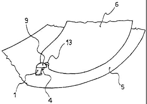
With reference to all the figures, the anti-fog visors assembly according
to the present invention comprises at least an external visor 5 made of
a scratch resistant material, such as polycorbonate, and at least an
internal visor 6 made of an anti-`og hydrophilic material, such as for
example cellulose acetate, which visor 6 is coupled to the external
visor 5 byway of mechanical retaining means 1, 2 (or 101, 2). Such
retaining means comprise at least two retainers 1, 1' (or 101), coupled
to the external visor 5 and suitable to lodge the aforesaid internal visor
6 in the middle, so to lock it. According to the known technique, the
retainers 1. 1'; 101 can retain the internal visor 6 to the external visor 5
in a fix way by transmitting a preset tension at corresponding concave
seats 13, 13', which the internal visor 6 may be laterally provided with,
and/or by preventing, through interposition of parts, the sliding of the
internal visor 6 with respect to the some retainers 1, 1'; 101.
Advantageously, according to the present invention, at least one of
such retainers 1, 1'; 101 is a pin 1; 101 pivotoble with respect to the
internal visor 6 and provided with a portion 4: 104 for the engagement
with the some internal visor 6, which portion 4; 104 provides at least ^
region 14; 1 1 4 for the loose engagement and at least a region 15: 1 15
for the tight engagement with the some visor 6, depending on the
rotation angle achieved by the pivotable pin 1; 101.
At this point and in the following description "region for the loose
engagement" it is intended a region of the engaging portion 4 for the
only partial engagement, or at least for a complete disengagement,
of the same portion with the internal visor 6, which allows the user to
easily disengage the internal visor 6 from the retainers 1, 1'; 101; while
for "region of tight engagement" it is intended a region of the portion
4 which, because of the geometric characteristics of the parts, allows
8
CA 02481159 2004-09-10
for a firm engagement of the some internal visor 6 with the external
visor S.
According to the present invention, the pin 1; 101 is also fixed to
means 3 for imposing the rotation of the some pin 1; 101 and which
extend to the outside of the external surface of the external visor 5, i.e.
directed toward the airflow impinging the helmet and opposed to the
visor 6.
Such means 3, for example constituted by a shaped part securely
fixed to the pivotable pin 1; 101 and extended externally from the
external visor 5, may be easily made integral with the pin 1; 101 or may
be jointed to this latter in a second moment, and allow the manual
operation, by rotation, of the some pin 1; 101 by the user, permitting
his operation externally from the visors assembly according to the
present invention.
In the preferred embodiment shown in the figures 1-6. the mechanical
retaining means of the visors assembly according to the present
invention comprise two pins 1, 1' engaged with the external visor 5,
which project from the internal surface of this latter, and which are
shaped to fit with two corresponding concave seats 13, 13' laterally
provided along the edge of the internal visor 6.
In the shown embodiment, the dimensions of the internal visor 6 and of
its lateral seats 13, 13', also the distance between the retainers 1, 1',
and their shape, allow the retaining of the internal visor 6 in full
contact with the internal surface of the external- visor 5, in a elastically
deformed structure of said infernal visor 6, so to ovoid humid air from
flowing between the two visors 5, 6.
In particular, the internal visor 6, which preferably may have a
curvature radius R6 higher than the curvature radius Rs of the external
visor 5, is elastically deformed (bended) during its assembling between
9
CA 02481159 2004-09-10
the retainers 1, 1' and is kept in such deformed shape by the same
retainers 1, 1' that impose a certain tension on the internal visor 6,
thanks to their coupling with the correspondent seats 13, 13'. The
elasticity of the material of the internal visor 6 and the bending to
which the same internal visor 6 is subject permit an optimal retaining
by the retainers 1, 1'.
At least one of the retainers 1, 1' according to the present invention is
constituted by a pin 1 which is mounted on the external visor 5 in a
pivotable way around an axis X-X. incident the some external visor 5,
and which comprise a portion for the engagement with the internal
visor 6 constituted by a cylindrical body 4, having a circular base,
eccentrically located with respect to the aforesaid rotation axis X-X of
the pin 1, In other words, the circular base cylindrical body 4 has its
symmetry axis parallel to the rotation axis X-X of the pin 1, standing
aside from said rotation axis X-X, so to cam couple itself with a
corresponding seat 13, 13' laterally provided on the same internal visor
6.
The pin 1, as it will be clarified later, is also jointed with means 3 for
transmitting the rotation which, advantageously, extend to the
external side of the external visor 5, so to allow an easy operation by
rotating the some pin 1 from the user.
Thus, with particular reference to figures 3a and 3b, the rotation of the
pin 1, thanks to the means 3, allows the cylindrical body 4 to gradually
move from a first, angular position, wherein a region (or at least a
point) 14 for the loose engagement engages the respective seat 13 of
the visor 6, to a second angular position wherein a different region (or
point) 15 for the tight engagement engages the same seat 13, and
vice versa.
In the case that exclusively the pin 1 is of the pivotable type provided
CA 02481159 2004-09-10
with a body 4 arranged in an eccentric way, when the region 14
engages the internal surface of the concave seat 13, the arrn d
between the rotation axis X-X and the engaging surface of the body 4
is minimum and thus the distance between the outermost engaging
points of the pin 1 and of the retainer I' to the internal visor 6 is the
maximum, in this way imposing a minimum, or at least null, tension on
the some visor 6 by the retainers 1, 1. In this configuration, as
immediately evident, the assembling or the removal of the internal
visor 6 within the retainers 1, 1' is thus made easier.
On the contrary, when the pin I is rotated, manually operating on the
means 3, in such a way that the region 15 - wherein the arm D
between the rotation axis X-X and the coupling surface of the body 4
is the maximum - engages the corresponding seat 13, the distance
between the outermost engaging points of the pin 1 and the retainer
1' with the visor 6 is the minimum, this requiring the application of a
maximum tension on the internal visor 6 by the retainers 1, 1. This
configuration, wherein a maximum tension is applied on the internal
visor 6, avoids or highly interferes with every displacement of the
internal visor 6.
When both the retainers 1. 1' are of the pivotable type having an
eccentrically arranged cylindrical body for the engagement, the
contemporary angular positioning of the pins 1, 1' - achievable
through the corresponding external means 3 for imposing the rotation
of the pins 1, 1', in such a way that the regions of the eccentric
cylindrical body 4 for the engagement with the minimum arm d
engage the respective concave seat 13, 13' of the internal visor 6 -
leads to obtain the maximum distance between the retaining points of
the some internal visor 6, in this way determining the application of
minimum tension to this latter, i.e. leading to a loose linking between
11
CA 02481159 2004-09-10
the pins 1, 1' and the visor 6.
On the contrary, the application of the maximum tension on the
internal visor 6 will be achieved when the regions for the engagement
with the maximum arm D are contemporary in engagement with the
concave seats 13, 13' - thanks to the rotation of the pins 1, 1' - in this
way carrying out a fight link between the pins 1, 1' and the visor 6.
As described above, the rotation of one or both pins 1, 1' of the
embodiment of the figures 1-6 permits to modify the engagement
conditions of the internal visor 6 with the external visor 5 depending
one the angular position achieved by the pins 1, 1', thus adjusting
substantially in a continuous way (thanks to the eccentric
arrangement of the body 4) the tension which the internal visor 6 may
be subject to, when the visor 6 has an elastically deformed structure
which put the same visor 6 in partial or full contact with the internal
surface of the visor 5.
Such modifications of the engagement conditions thus permit to the
manufacturer to provide lower tolerances during the production of
the parts of the above mentioned visors assembly and allow the user
to assembly or disassembly the internal visor 6 by easily operating from
the outside of the external visor 5, by way of the aforesaid means 3 for
the application of the rotation to the pins 1, 1', with no need for a first
disengagement of the external visor 5 from the helmet cover and
without the necessity of specific tools. Moreover, in the case wherein
dimensional variations of the internal visor 6 are provided. due for
example to the wearing or to creep events, the simple rotation of at
least one of the pins 1, 1' also permits to improve the tension which the
internal visor 6 is subject to, so that a tight contact between the two
visors 5, 6 is ensured.
In a preferred embodiment of the present invention, illustrated in detail
12
CA 02481159 2004-09-10
in the figures 2. 3a and 3b, each pin 1, 1' may also be provided with
an upper blocking tab 9, suitable to avoid accidental disengagement
of the seats 13, 13' with the engagement regions of the eccentric
cylindrical bodies 4. Each blocking tab 9, provided above the internal
surface of the visor 6, radially extends from the pin 1, 1' only according
to an angular range (which comprises the region 15) wherein a tight
coupling of the some eccentric cylindrical body 4 with the respective
seat 13. 13' of the visor 6 occurs, in such a way that the tab 9 does not
impede the removal of the visor when the region 14 for the loose
engagement is brought into engagement with the respective seat 13,
13'.
Furthermore, in the embodiment shown in the figures 1-6, the pins 1, 1 '
are linked to the external visor 5 in a rotatable way with respect to the
some visor, thanks to the engagement of such pins 1, 1' with the
correspondent caps 2. 2', which extend to the outside of the visor 5
through respective holes 7 provided on the same visor 5. The geometry
of the caps 2, 2' and the pins 1, 1' prevents the group constituted by
each pin 1, 1' fixed to the respective external cap 2, 2' from slipping
off from the hole 7 and af'the some time permits the jointly rotation of
such group around the axis X-X within the hole 7.
it has to be noticed that, in alternate embodiments not shown, each
cap 2 may be integral with the external visor 5 and may engage the
correspondent pin 1, 1' in such a way to allow its relative rotation with
respect to the some cap 2. 2' which, thus, is fixed with respect to both
visors 5, 6.
With reference to the figures 3a, 3b and 4a, 4b, in the particular
embodiment shown, each external cop 2, 2' comprises an upper
portion 10 below which a cylinder 11 projects, provided with a spline
12 and with projections 20. The upper portion 10 comprises a shaped
i3
CA 02481159 2004-09-10
end 3 directed toward the outside of the external visor 5, which end is
suitable to simplify the manual operation - in rotation around the axis
X-X - of the cap 2 or 2' and the related pin 1 or 1' by the user and
which is thus an essential port of the aforesaid means for imposing the
rotation to the pin 1 or 1.
In particular, the lower cylinder 11 is shaped for internally engage a
correspondent hollow seat 8 obtained within the pin 1, 1' and
provided with a casing 21 for the spline 12. The hollow seat 8 also
comprises grooves, not shown, suitable to snap couple with the
projections 20, i.e..through interposition of parts upon the spring back
of the some projections 20. The snap coupling of the pin 1, 1' with the
cap 2, 2' ensures the axial engagement between the two parts, while
the presence of the spline 12, which engage within the casing 21',
provides the rotation of the cap 2 or 2' jointly with the pin 1 or 1'.
Although the application of an external cap 2, 2' has been described,
suitable io retain in a rotatable way each pin 1, 1' to the external visor
5, other known means may be provided for the engagement of the
pin 1 to the some visor, as well as suitable means for imposing the
rotation of the same pin 1, 1' may be provided, which extend to the
outside of the visor 5, For example, the pin 1 may comprise an
elastically deformable portion suitable to engage the hole 7 and
provided with a grip end for the user.
The figures 7 and 8 show an alternate embodiment of the present
invention particularly convenient when the infernal visor 6 is partially
brought in abutment with the internal surface of the external visor 5,
preferably in correspondence of one peripheral edge. For example,
the external surface of the internal visor 6, as disclosed in the above
mentioned patent US 6405373 (GRAU), may be provided with a frame
117 made of a material impermeable to fluids, such as a silicone
14
CA 02481159 2004-09-10
material, arranged in correspondence of the peripheral edge of said
external surface of the visor 6 and suitable to engage the external
visor 5.
By providing this solution, it is possible to use the retainers 101 which
can simply retain the internal visor 6 in partial engagement with the
visor 5. by way of a shaped area 116 which stands on the internal
surface of the some visor 6, with no need for said retainers 101 to
necessarily transmit an adjusting tension on the internal visor 6.
More in detail, according to a peculiar aspect of the present
invention, each pin 101 of the embodiment shown in the figures 7 and
8 comprises a portion for the engagement with the internal visor 6
constituted by an upper tab 104 which extend beyond the visor 6 of
an angular range around the rotation axis X-X of the pin 101. Such tab
104 provides a first region 115 for the tight engagement, which
1s comprises a projection 116 shaped for engage the internal surface of
the visor 6 so to transmit a certain pressure to the last, and a second
region 114 for the loose engagement, without the elements for the
engagement with the same visor 6.
The pin 101, as similarly described with reference to the figures 1-6, is
coupled in a pivotable way to the external visor 5, through the hole 7
provided within the visor 5, by way of its coupling to an external cap 2,
which is opportunely shaped for snap engage the same pin 101 -
using a spline - and which is provided with a shaped portion 3 for
permitting the operation of the pin 101, by its rotation, from the outside
of the external visor 5.
The rotation of the pin 101 around the axis X-X of figure 7 allows the
user to alternatively engage the tight engagement region 115 with the
internal visor 6, in this way retaining the some visor 6 in partial contact
with the external visor 5, and with the loose engagement region 114.
I5
CA 02481159 2004-09-10
thus freeing the internal visor 6.
In view of the above, the skilled man will clearly understand that
providing pivotable pins of the above mentioned type - i.e. pins which
comprise a portion for the engagement with the internal visor having
at least a region for the loose engagement and a region for the tight
engagement depending on the rotation angle achieved by a some
pivotable pin and which are provided with means for imposing the
rotation extending outside the external visor, in an anti-fog visors
assembly of the type having on internal anti-fog visor which is placed
on an external anti-scratch visor - permits to make the tolerances of
the ports of such visors assembly higher, with consequent economic
advantages, permits to easily mount or dismount the internal visor
without the necessity for preventively disengage the external visor
from the helmet cover, and permits, when it is required, to adjust in a
precise way the tension which the internal visor may be subject to.
16