Note: Descriptions are shown in the official language in which they were submitted.
CA 02481393 2008-06-27
1
Panel and Interlocking System for Panels
The invention relates to a locking system for panels with
edge profiles provided on at least two opposite edges of the
panels for the positive connection of similar panels,
including an edge profile designed as a groove profile, with
an upper groove wall with a snapped off, abutting surface and
a lower groove wall, and an edge profile designed as a tongue
profile, with a snap projection on the underside of the
tongue that engages a snap recess in the lower groove wall of
an adjacent panel in the assembled state, where the engaged
edge profiles form an articulated joint that acts to restore
the panels to their installation plane when deflected either
up or down. The invention also relates to a panel with the
locking system according to the invention.
Locking systems of this kind are used for floor panels, for
example, such as parquet panels with a natural wood surface
or laminated panels. The latter have a core made of MDF, HDF
or particle board and are provided with a reproduced surface
made of a decorative laminate.
299 11 462 Ul discloses a generic locking system, whose
connection has the function of an articulated joint. Locking
systems of this kind are used for floor coverings, which, for
example, lie on uneven bases or must bear deflection in the
connection area due to the presence a soft backing, such as
impact sound insulation. Deflection of the connection causes
high stresses in the region of the tongue-and-groove profiles
of two locked panels, because the connection bends under the
load. The panel material cannot withstand the high stresses
CA 02481393 2004-10-04
2
in the region of the edge profiles and fails in the
connection area.
The ease of installation of the known jointed locking system
leaves much to be desired. Its resistance to being pulled
apart in the installation plane does not meet expected,
future quality standards for floor coverings with mechanical
locking systems. Furthermore, the known joint connection can
be installed in two ways, where the second installation
method described is associated with the undesirable side
effect that the connection displays particularly low
resistance to being pulled apart.
According to the first installation method, a new panel,
preferably tongue-first, is placed at an angle against a laid
panel and then folded or rotated downwards until it lies in
the common installation plane of the panels and locks
automatically.
In the second installation method, locking occurs when both
panels are in the installation plane, namely by sliding the
panels laterally towards one another. The panels can only be
snapped together in this way because the undercut between the
snap projection of the tongue and the snap recess in the
lower groove wall is designed to be correspondingly small.
The snap connection achieved in this way is of such low
strength that gaps can form between abutting surfaces of
adjacent panels due to normal changes in length of the floor.
This is the case, for example, when the temperature of the
floor fluctuates. This method of jointing also results in
immediate damage to the edge profiles, because they must be
subjected to strong deformation in order for the undercut of
the tongue and the lower groove wall to engage.
Furthermore, the tongue of the known locking system has a
long, tapered shape. The top of the tongue has an inclined
surface that is intended to facilitate insertion of the
I = '
CA 02481393 2004-10-04
3
tongue tip into the groove. In reality, however, the tongue
proves to be very easily damaged due to its tapered shape.
This has a disadvantageous effect on the product's ease of
installation, service life and utility.
The object of the invention is to design a locking system for
an articulated panel connection, which is easier to handle,
displays greater resistance to being pulled apart and has a
longer service life than the known locking system.
According to the invention, the object is solved in that the
upper groove wall has a flank on the inside that opens
towards the free end of the groove wall, and that the tongue
profile has a blunt surface on its free end.
Providing a flank on the upper groove wall 'creates a wide
groove opening on the groove side of a panel, into which the
tongue profile of an adjacent panel can be inserted more
easily than the known, tapered tongue profile into the
narrower groove opening of the known locking system.
The flank preferably transitions into a levelling surface
extending towards the groove base, which ensures exact
vertical positioning without vertical offset between locked
panels. In other words, the segment of the inside of the
upper groove wall running from the flank to the base of the
groove forms the levelling surface, the distance of which to
the surface of the panel is precisely equal to the distance
of the top side of the tongue to the surface of the panel,
meaning that no vertical offset occurs between locked panels.
The flank can be of curved or plane design, where a straight
shape is expedient for manufacturing purposes and a curved
shape is somewhat more favourable for the panel joining
procedure in terms of stress. When the tongue profile comes
into contact with the curved flank of the groove profile, the
surface pressure is somewhat lower than in the case of
CA 02481393 2004-10-04
4
contact between the tongue profile and the edge on the end of
the plane flank.
A levelling surface is also provided on the top side of the
tongue, which interacts with the levelling surface of the
upper groove wall when the panels are joined. Since the upper
groove wall has a flank on the free, front end=, the levelling
surface of the tongue is only in partial contact with the
levelling surface of the upper groove wall, namely in the
region of the free end of the tongue. If the levelling
surface of the tongue were in contact with the upper groove
wall along the entire length of the top tongue surface, a
rigid connection would result. The flank lends.the connection
a degree of flexibility that favours the joint function of
the connection and reduces stress in the material of the edge
profiles.
In the event of deflection of the connection towards the
installation base, in particular, the flank creates room for
movement, so that the top side of the tongue can be moved
towards the flank without coming up against it prematurely.
The flexibility of the connection achieved in this way
enables articulated movement without rupturing the tongue or
damaging the groove walls due to excessive stress.
The handling and service life of the locking system are
improved if the tongue length, meaning the distance by which
the tongue protrudes beyond the upper edge of the panel, is
less than or equal to the thickness of the upper groove wall
of the groove profile. A tongue of this length is short
compared to the prior art. The short tongue has the advantage
that only a relatively short insertion path has to be
travelled when the tongue is inserted at an angle into a
groove profile. Consequently, the proposed locking system is
particularly easy to handle during installation and can be
installed much more quickly than the known locking system.
CA 02481393 2004-10-04
The blunt surface on the free end of the tongue is more
robust _and durable compared to the tapered shape of the
tongue of the known locking system.
5 The groove depth of the groove profile, meaning the distance
the groove recedes beyond the upper edge of the panel, is
favourably greater than the tongue length described above by
roughly half. In other words, if the groove depth starting
from the upper edge of the panel is 3/3, the tongue protrudes
into the groove by a tongue length of 2/3 when two panels are
assembled, leaving a space with a residual depth of 1/3 the
groove depth between the free end of the tongue and the
groove base. Such a large groove depth would not be necessary
to simply accommodate the tongue in the groove. However, the
large groove depth influences the flexible length of the
lower groove wall protruding freely from the edge of the one
panel. This makes the connection flexible, reduces stress in
the material and thus increases the service life of the
connection.
The flexible length of the lower groove wall preferably
roughly corresponds to the thickness of the panel. This is
because the spring travel required on the f'ree end of the
lower groove wall is then relatively short referred to the
length of the tongue, and the elastic expansion occurring
during joining of the panels causes only little stress in the
material, which can be withstood without difficulty.
The depth of the snap recess in the lower groove wall
expediently amounts to roughly one-third the thickness of the
tongue. This results in a degree of undercut in the assembled
state that prevents the panels from being pulled apart in
installed state under normal conditions of use. Compared to
conventional mechanical locking systems according to the
prior art, which are locked by means of horizontal sliding in
the installation plane, the degree of undercut of the locking
system according to the invention is roughly doubled and, as
CA 02481393 2004-10-04
6
a result, the resistance of panels against being pulled apart
in the installation plane dramatically increased.
For the purpose of material-saving manufacture, the offcut
dimensions on the edges of the panels are relatively small.
They preferably differ on the groove side and the tongue
side.
On the groove side of a panel, the resulting offcut of the
decorated surface is favourably less than half the panel
thickness.
On the tongue side of a panel, the resulting of f cut of the
decorated surface is preferably roughly between 1/3 and 1/4
the thickness of the panel. It essentially corresponds to the
length the tongue protrudes beyond the upper edge of the
panel.
A panel, particularly a floor panel, is expediently equipped
with a locking system according to the invention. The locking
profile is preferably used for laminated flooring panels,
which comprise a core material made of HDF, MDF or particle
board, where the edge profiles of the locking system are
milled into the edges of the panels.
An example of the invention is illustrated in a drawing and
described in detail below on the basis of figures. The
figures show the following:
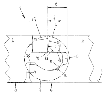
Fig. 1: A locking system consisting of a tongue profile and
a groove profile of two joined panels,
Fig. 2: The locking system according to Fig. 1 during
joining,
Fig. 3: The locking system according to Fig. 1, where the
articulated connection is lifted off the base and
= =
CA 02481393 2004-10-04
7
deflected upwards,
Fig. 4: Locking system according to Fig. 1 with a joint
deflected downwards towards the installation base.
According to the drawing, locking system 1 consists of two
positively engaging edge profiles provided on the edges of
panels 2 and 3. The edge profiles are largely designed to be
complementary to one another as groove profile 4 and tongue
profile 5. Groove profile 4 on one edge of a panel 2 or 3 is
always opposite a tongue profile 5 on the opposite edge of
the same panel 2 or 3. In this way, identically profiled
panels 2 and 3 can be connected to one another. Locking
system 1 is expediently provided on all opposing sides of a
panel 2 or 3.
The configuration described relates to floor panels equipped
with the locking system according to the invention. Of
course, the locking system can also be used for wall and
ceiling panels, or for panels for fence or house
construction, where the problem of deflection occurs to a
lesser degree.
Figure 1 shows that the locking system according to the
invention involves a modified tongue-and-groove profile.
Groove walls 6 and 7 of groove profile 4 protrude different
distances beyond the edge of panel 3. Segments 8 and 9
adjacent to tongue 10 of tongue profile 5 recede different
distances beyond the edge of panel 2. Protruding groove walls
6, 7 and receding areas 8, 9 of groove profile 4 and tongue
profile 5 are adapted to one another such that they can be
joined. In order to secure the lock against panels 2 and 3
being pulled apart in the installation plane, a concave snap
recess 11 is incorporated on the inside of lower groove wall
7 that is engaged by a convex snap projection 12 in the
assembled state according to Fig. 1. Convex snap connection
12 is provided on the underside of tongue 10 facing
i e .
CA 02481393 2004-10-04
8
installation base U. On the free, protruding end of lower
groove wall 7, a shoulder 13 provides resistance to tongue 10
of panel 2 being pulled out of groove profile 4 of adjacent
panel 3 in the horizontal plane.
Figure 1 further shows that the edges of the edge profiles
only contact one another in three areas. The first is the
upper edge of the two panels 2 and 3 facing away from
installation base U, where a tight, gapless joint is located.
Abutting surfaces 14 and 15 are in contact here. The second
contact area is the one between the top side of the tongue
and the inside of the upper groove wall. Here, levelling
surfaces 16 and 17 of the two edge profiles are in contact
with one another, where both levelling surface 16 of tongue
10 and levelling surface 17 of upper groove wall 6 are at
exactly the same distance from the top side of the respective
panel 2 or 3. A vertical offset between joined panels 2 and 3
is avoided in this way. The third contact area is the contact
between concave snap recess 11 of lower groove wall 7 and
convex snap projection 12 of tongue 10. This contact area is
located on the part of snap recess 11 facing the free end of
lower groove wall 7. Generously dimensioned spaces 18, 19 and
20 are provided between these contact areas, meaning that
contact really only ever occurs at the desired contact areas,
a gapless, tight joint is ensured on the top side of the
floor covering, and no vertical offset occurs.
In the present practical example, plane flank 21 is provided
on the inside of upper groove wall 6, the result being that
only in the region of its free end does the top side of the
tongue act as levelling surface 16, which is in contact with
levelling surface 17 of upper groove wall 6. Figure 1 shows
tongue length f, by which tongue 10 protrudes beyond the
upper edge of panel 2. This tongue length f is less than or
equal to thickness n of upper groove wall 6. In this case,
the protrusion of tongue 10 is relatively small. Inclined
flank 21 on upper groove wall 6 results in the formation of
CA 02481393 2004-10-04
9
mouth-like opening 22, into which short tongue 10 can be
inserted very easily. Moreover, short tongue 10 results in a
very short insertion path until tongue 10 is completely
inserted in the groove. The manual assembly of panels
equipped with this locking system is very simple and
substantially faster than with panels provided with the known
locking system.
Groove depth t, by which the groove recedes beyond the upper
edge of panel 3, is greater than tongue length f by roughly
half. A groove depth t of this kind would not be necessary to
accommodate tongue 10. However, it promotes the flexibility
of groove walls 6 and 7, particularly of lower groove wall 7,
which must be slightly elastically expanded in order to join
panels 2 and 3. The elasticity of the material results in a
restoring action. Panels 2 and 3 spring back into the initial
position shown in Fig. 1, in which both panels are located in
a common plane. Resulting space 19 further serves to
accommodate dirt particles that can get into the joint during
installation of panels 2 and 3. In addition, the joint can be
improved by adding glue in space 19, in which case, however,
the joint characteristics of the connection change, depending
on the glue selected.
Figure 2 shows the positioning of panel 2 with tongue profile
5 against groove profile 4 of panel 3, which is already
located on installation base U.
Blunt, free end 23 of tongue 10 can be inserted very easily
at an angle and over a short insertion path into groove
profile 4 of laid panel 3, which has wide, mouth-like opening
22 due to the flank. Three contact points result in the
initial position of the joining motion, as shown in Fig. 2. A
first edge contact 24 is formed on the upper edge of panels 2
and 3. A second edge contact 25 is formed between the top
side of the tongue and upper groove wall 6, and a third
contact 26 between convex snap projection 12 of tongue 10 and
= =
CA 02481393 2004-10-04
concave snap recess 11 of lower groove wall 7. Starting in
the position shown in Fig. 2, continuation of the joining
procedure causes minimal expansion, essentially due to the
elastic deflection of lower groove wall 7 towards
5 installation base U. In this way, convex snap projection 12
of tongue 10 is moved into snap recess 11 of lower groove
wall 7 and the final position of panels 2 and 3 reached, as
shown in Fig. 1. In this position, snap projection 12 of
tongue 10 engages the shoulder of lower groove wall 7 and
10 ensures a secure hold against pulling apart in the horizontal
plane.
Figures 3 and 4 show locking system 1 in such a way that the
joint function of the connection is apparent.
Locking system 1 is used, for example, for floor coverings
lying on uneven installation bases U. With uneven
installation bases U of this kind, it can occur that panels 2
and 3 have no contact with the ground in the region of a
joint and a space exists. When a load is applied in the
region of the joint, it bends. Consequently, deflection of
the edge profiles must be tolerable in the joint region. The
joint may also bend on a level installation base U. This can
happen when panels 2 and 3 are laid on a soft backing, such
as impact sound insulation.
In order to withstand such loads, design measures are
provided that lend the joint the articulated'flexibility it
needs. This flexibility prevents deflection of the joint from
causing such high stresses in the region of groove profile 4
and tongue profile 5 that the material of panels 2 and 3
fails under the high stress. The positions shown in Figs. 3
and 4 are arbitrary positions of movement and do not
represent limit positions of the joint motion.
Figure 3 shows the joint deflected upwards, i.e. away from
installation base U. In this position, slight elastic
. =
CA 02481393 2004-10-04
11
deflection again occurs essentially on lower groove wall 7.
Due to its elasticity, lower groove wall 7 has a restoring
effect on panels 2 and 3, as soon as the load is removed. The
movement of the joint reduces space 20 between the root of
tongue 10 and shoulder 13 of lower groove wall 7. In this
way, existing space 20 permits articulated flexibility of the
joint. In contrast, space 18 becomes larger.
Figure 4 shows deflection of the locking system in the
opposite direction, towards installation base U. Elastic
expansion, essentially of lower groove wall 7, is again
evident in this case, which likewise has a restoring effect
on panels 2 and 3 when the load is removed. The movement of
the joint reduces space 18 between tongue 10 and flank 21 of
upper groove wall 6. In this case, space 18 permits the
articulated flexibility of the joint. In contrast, space 20
becomes larger.
- - -------------
I ' .
CA 02481393 2004-10-04
12
Akzenta Paneele + Profile GmbH
D-56759 Kaiserseach
Panel and locking system for panels
List of reference numbers
1 Locking system
2 Panel
3 Panel
4 Groove profile
5 Tongue profile
6 Upper groove wall
7 Lower groove wall
8 Segment
9 Segment
10 Tongue
11 Concave snap recess
12 Convex snap projection
13 Shoulder
14 Abutting surface
15 Abutting surface
16 Levelling surface
17 Levelling surface
18 Space
19 Space
20 Space
21 Flank
22 Mouth-like opening
23 Blunt end
24 Edge contact
25 Edge contact
26 Contact
f Tongue length
n Thick, upper groove wall
CA 02481393 2004-10-04
13
p Groove depth
U Installation base