Note: Descriptions are shown in the official language in which they were submitted.
CA 02481900 2004-10-07
WO 03/087781 PCT/US03/10978
VISCOSITY AND VISCOELASTICITY MEASURING INSTRUMENT
BACKGROUND OF THE INVENTION
Field of the Invention
The present invention relates to fluid measurements,
more particularly, to an instrument for measuring the
viscosity of fluids.
The Prior Art
It has been known that the viscoelasticity, or
tackiness, of some bodily fluids change in response to bodily
rhythms. For example, the cervical mucus and saliva of a
female has a maximum fluidity just before ovulation, where
ovulation is defined as the moment that an ovum is released
from the follicle. This knowledge led to the applicant's
previous activities in the development of techniques for
monitoring the viscoelasticity, or tackiness, and other
properties of cervical mucus and saliva as predictors of time
of ovulation and to improvements in rheometer or viscometer
apparatus for measuring such viscoelastic properties. See,
for example, L.E. Kopito and H.J. Kosasky, "The Tackiness
Rheometer Determination of the Viscoelasticity of Cervical
Mucus," Human Ovulation, edited by E.S.E. Hafez, Elsevier,
North-Holland Biomedical Press, 1979, pp. 351 et seq., S.S.
Davis, "Saliva is Viscoelastic", Experientia, 26:1298,
(1970), R.H. Davis et al., "Saliva Viscosity Reflects the
Time of Ovulation", Experientia, 30:911, (1974), and U.S.
Patent Nos. 4,002,056 and 4,167,110.
It is also known that the normal viscoelasticity of some
bodily fluids changes in response to abnormal body
conditions. For examples in a newborn baby with cystic
fibrosis, the meconium, the first bowel movement of a
newborn, has a viscoelasticity approximately five times that
of a baby without cystic fibrosis.
There are a number of devices available for measuring
viscosity. The above-identified Patent No. 4,779,627, in
addition to disclosing a process for determining female
1
CA 02481900 2004-10-07
WO 03/087781 PCT/US03/10978
ovulation time by measuring. saliva viscoelasticity, discloses
a device for measuring the viscoelasticity of the sublingual
saliva. The device has a shape somewhat like a syringe, with
an outer cup, an inner cup concentric with and located within
the outer cup, and a plunger. A roughened surface on the end
of the plunger holds the saliva sample. The plunger is
inserted into the inner cup until the saliva sample is
compressed against the bottom of the inner cup. A
predetermined amount of weight pulls the inner cup downward,
stretching the saliva sample. If the visCOelasticity of the
salvia as low, the saliva sample will fracture, causing the
inner cup to fall to the bottom of the outer cup. An
indicator at the bottom of the outer cup indicates that the
inner cup has fallen to the bottom, which, in turn, indicates
that ovulation will soon take place. If, however, the
viscoelasticity of the saliva is high, the saliva sample will
hold the plunger and inner cup together so that the inner cup
will not fall to the bottom, indicating that ovulation will
not take place in the near future.
The main disadvantage of the device is that it must be
taken apart in order to take a sample. The plunger must be
removed from the inner cup before being inserted in the mouth
to obtain a saliva sample. This has the potential for the
person to easily contaminate the saliva sample by incorrectly
reinserting the plunger after taking the sample, invalidating
the measurement.
U.S. Patent Nos. 5,640,968, 5,851,190, and 6,149,604
disclose handheld instruments for measuring saliva
viscoelasticity. The instruments are designed specifically
for saliva, which means that their range of measurement is
very limited, and cannot measure the viscosity or
viscoelasticity of dense fluids. such as meconium.
2
CA 02481900 2004-10-07
WO 03/087781 PCT/US03/10978
SUN.~2ARY OF THE INVENTION
An object of the present invention is to provide an
instrument that can measure a wide range of viscosities and
viscoelasticities.
The viscosity and viscoelasticity measuring instrument
of the present invention includes a housing within which the
measuring mechanism resides. The components of the measuring
mechanism include a cam, a follower arm, a spring, and a
plate fixture. The cam is a vertical, circular disk with a
spiral slot that is rotated by an electric stepper motor. A
cam follower attached to the follower arm resides in the
spiral slot so that, as the cam rotates, the follower arm
pivots upwardly or downwardly about its fixed end. The
spring is a flat, preferably metallic, strip, one end of
which is attached to and collinear with the fixed end of the
follower arm. Thus, the spring pivots in the opposite
direction as the follower arm. The plate fixture holds a
removable plate assembly that has three components, a lower
plate, an upper plate, and a plate clip. The two plate
components have mating sample surfaces on which the fluid to
be tested is placed. The fixture has a lower jaw pivotally
attached to the instrument base and an upper jaw pivotally
attached to the free end of the spring. The pivoting
attachments allow the plate sample surfaces to align as they
come together during a test. The jaws have channels for
receiving and holding the plates.
To perform a measurement, a fluid is placed on the lower
sample surface. The cam rotates, pushing the free end of the
follower arm upwardly, causing the follower arm to pivot
about its fixed end. The spring, attached to the fixed end
of the follower arm, rotates downwardly, pressing the sample
surfaces of the upper and lower plates together. Then the
cam is reversed, causing the spring to impart a separation
force on the plates. The amount of time it takes for the
plates to separate is measured and converted to a viscosity
3
CA 02481900 2004-10-07
WO 03/087781 PCT/US03/10978
value. A strain gauge mounted to the spring indicates when
the plates separate.
Other objects of the present invention will become
apparent in light of the following drawings and detailed
description of the invention.
BRIEF DESCRIPTION OF THE DRAWINGS
For a fuller understanding of the nature and object of
the present invention, reference is made to the accompanying
drawings, wherein:
Fig. 1 is a perspective view of the front of the
instrument of the present invention;
Fig. 2 is a perspective view of the rear of the
instrument of the present invention;
Fig. 3 is a front elevational view of two measurement
plates;
Fig. 4 is a front elevational view of the measurement
plates of Fig. 3 with a fluid sample;
Fig. 5 is a front elevational view of the measurement
plates of Fig. 3 pressed together;
Fig. 6 is a front elevational view of the measurement
plates of Fig. 3 separating after pressure is released;
Fig. 7 is a perspective view of the instrument of Fig. 1
with the cover removed;
Fig. 8 is a side view of the instrument of Fig. 7 in its
resting state;
Fig. 9 is a side view of the instrument of Fig. 7 in its
first operative state;
Fig. 10 is a side view of the instrument of Fig. 7 in
its second operative state;
Fig. 11 is a view of the cam of Fig. 7;
Fig. 12 is a side view of the main spring and leaf
spring in compression mode;
Fig. 13 is a side view of the main spring and leaf
spring of Fig. 12 in separati~n mode;
4
CA 02481900 2004-10-07
WO 03/087781 PCT/US03/10978
Fig. 14 is an exploded, partial phantom view of one
configuration of the plate fixture of Fig. 7;
Fig. 15 is an exploded, partial phantom view of another
configuration of the plate fixture of Fig. 7;
Fig. 16 is a perspective front view of one embodiment of
the removable plate assembly;
Fig. 27 is an exploded rear perspective view of the
removable plate assembly of Fig. 16;
Fig. 18 is a rear view of the removable plate assembly
of Fig. 16;
Fig. 19 is a perspective front view of a second
embodiment of the removable plate assembly;
Fig. 20 is a top view of the overlapping sample surfaces
of the removable plate assembly;
Fig. 21 is an enlarged cross-sectional view of a
roughened sample surface; and
Fig. 22 is a block diagram of the electronic control
circuit of the present invention.
DETAILED DESCRIPTION OF THE INVENTION
The basis of the viscosity and viscoelasticity measuring
instrument of the present invention is that it is possible to
determine the viscosity of a fluid by measuring the time it
takes for the fluid to fracture under known conditions. The
known conditions include the amount of force pulling the
fluid apart, the area of the fluid over which the force is
exerted, and the fluid temperature. In the present
specification, unless otherwise indicated, the term
"viscosity" refers to both viscosity and viscoelasticity,
The dynamic viscosity of a fluid sample is a function of
the separation force, the area of one of the sample surfaces
and the amount of time that it takes for the sample surfaces
to separate. These values are related by the following
equation:
CA 02481900 2004-10-07
WO 03/087781 PCT/US03/10978
separation force * separation time
dynamic viscosity = -_------------_-----_-------------
surface area
wherein the dynamic viscosity is calculated in poise (P), the
separation force is measured in dynes (dy), the surface area
is measured in square centimeters (cm~), and the separation
time is measured in seconds (s). The separation
force/surface area is also called the shear stress. The
kinematic viscosity is the dynamic viscosity divided by the
density of the fluid and is in units of stokes (St). The
customary unit of dynamic viscosity is the centipoise (cP)
which has dimensions of P x 10'2, and the customary unit of
kinematic viscosity is the centistoke (cSt) which has
dimensions of St x 10'2.
Note that the equation is for viscosity, rather than for
viscoelasticity. When using a Newtonian fluid, such as
water, the equations will calculate pure viscosity. However,
some fluid samples are non-Newtonian fluids. In a non-
Newtonian fluid, there is an element of elastic recoil, or
elasticity, along with the viscosity. Elasticity affects the
separation time and separation force of the plates. Thus,
the measurements used in the above equation are affected by
the elasticity of the fluid sample. Because there is no
specific equation for viscoelasticity, the equation for
viscosity is used, and the viscoelasticity is measured in
viscosity-equivalent units, giving a Newtonian equivalent of
the combination of viscosity and elasticity found in a non-
Newtonian fluid samp~.e.
The portions of the determined viscoelasticity
attributed to the viscosity and to the elasticity depend upon
the thickness of the fluid sample (density, not breadth). As
the thickness increases, the portion attributed to viscosity
increases as a percentage of the viscoelasticity. For
example, in a very thick saliva, the proportion of viscosity
to elasticity may be 80% to 200, while in a very thin saliva,
the proportion may be 20% to 80%.
6
CA 02481900 2004-10-07
WO 03/087781 PCT/US03/10978
Another factor to consider is that, not only do the
proportions of viscosity and elasticity change as a fluid
thickens, but the absolute values of the viscosity and
elasticity also change. For example, a thick saliva may have
80% of its viscoelasticity attributed to viscosity and 20%
attributed to elasticity with absolute numbers of 64 cSt
attributed to viscosity and 16 cSt attributed to elasticity,
and a thin saliva may have 20% of its viscoelasticity
attributed to viscosity and 80% attributed to elasticity with
absolute numbers of 5 cSt attributed to viscosity and 20 cSt
attributed to elasticity.
Figs. 3-6 show the physical process by which the
viscosity of a fluid is measured. In Fig. 3, a pair of
plates 202 having sample surfaces 204 are spaced apart. In
Fig. 4, a fluid sample 206 of adequate volume is placed
between the sample surfaces 204. In Fig. 5, the plates 202
are pressed together with a predetermined compression force
208. The compression force 208 must be large enough so that
the fluid sample 206 coats the entire area of the sample
surfaces 204. In Fig. 6, the plates 202 are pulled apart by
a separation force 210 until the fluid sample fractures, as
at 212. Fracturing occurs when the cohesion of the fluid
sample 206 is overcome, where cohesion is defined as the
tendency of parts of a body of like composition to hold
together.
Measuring the viscosity of a fluid sample relies on the
adhesion of the fluid sample to the sample surfaces where
adhesion is defined. as the tendency, due to intermolecular
forces, for matter to cling to other matter. In order to
have a valid measurement, the force of adhesion of the fluid
sample to the sample surfaces must be greater than the force
of cohesion of the fluid sample so that the fluid sample
fractures before it separates from one of the sample
surfaces. Therefore, sample surfaces having a force of
7
CA 02481900 2004-10-07
WO 03/087781 PCT/US03/10978
adhesion for the fluid sample that is greater than the force
of cohesion of the same fluid sample must be employed.
The action represented by Fig. 6 implies two ways of
measuring: (1) using a known separation force 210 and
measuring the time it takes for the fluid sample 206 to
fracture, or (2) using a known separation time and measuring
the amount of separation force 210 needed to fracture the
fluid sample 206. The instrument of the present invention
indirectly employs the former. The equation above for
dynamic viscosity implies that the separation force,
separation time, and surface area must be known in order to
calculate the viscosity. The instrument of the present
invention, however, does not rely upon knowing the absolute
values of the separation force and surface area, only that
these values remain consistent from measurement to
measurement. This is accomplished by characterizing the
instrument to determine the separation time for fluids of
known viscosities. For example, the characterization
procedure will measure the separation times for fluids of
known viscosities, then interpolate and extrapolate from
these measurements to create a table mapping separation times
to viscosities. Alternatively, the viscosity is calculated
from the separation time by an equation and the
characterization data is used to scale the calculation for
the particular instrument.
The current external configuration of the viscosity
measuring instrument 10 of the present invention is shown in
Figs. 1 and 2, keeping in mind that the design shown is
merely illustrative, and that any design that is able to
perform the necessary functions is contemplated. Externally,
the instrument 10 includes a housing 11, a door 13, a visual
display 14, a characterization switch 15, a handle 16, a
power input plug 17, and power switch assembly 18, and an
optional external communications port 19. The purposes of
the housing 11, handle 16, power input 17, and power switch
8
CA 02481900 2004-10-07
WO 03/087781 PCT/US03/10978
18 are obvious. The door 13 is hinged downwardly and
provides access to the operator for inserting the removable
plate assembly 30, as described below. The visual display 14
both instructs the operator and informs the operator as to
the status of the instrument 10 and the test results. The
present invention also contemplates that there may not be an
internal display, and that the instructions, status, and
results will be sent to an external computer for display.
The characterization switch 15 instructs the instrument 10 to
perform an instrument characterization, as described below.
The optional external communications connector 19 provides a
means for an external computer to receive setup parameters
and test results and, optionally, to control the operation of
the instrument 10.
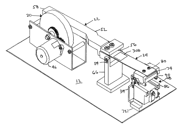
The internal mechanical components of the instrument 10,
shown in Figs. 7 and 8, include a cam 20, a follower arm 22,
a spring 24, and a plate fixture 28. In brief, a fluid for
test is placed on the test surface 114 of the lower plate 104
of the plate assembly 30 and the test is started. The cam 20
rotates, pushing the free end 58 of the follower arm 22
upwardly, causing the follower arm 22 to pivot about the
fixed end 56. The spring 24, attached to the fixed end 58 of
the follower arm 22, rotates downwardly, pressing the two
components of the plate fixture 28 together. The plates 102,
104 of the removable plate assembly 30, which are held by the
plate fixture 28, are pressed together. When the compression
force reaches a predetermined level for a predetermined
period of time, the cam 20 is reversed, eventually causing
the spring 24 to impart a separation force on the plates 102,
104. The amount of time it takes for the plates 102, 104 to
separate is measured. The time measurement is converted to a
viscosity value representing the viscosity of the sample
fluid either through a lookup table or an equation.
The cam 20, shown in detail in Fig. 11, is a circular
disk 32 with a spiral slot 34. In the illustrated
9
CA 02481900 2004-10-07
WO 03/087781 PCT/US03/10978
configuration, the slot 34 is approximately 0.255" inches
wide. The slot 34 encircles the center 3& of the disk 32,
starting at an inner end point 38 with a radius of
approximately 0.587", as at 42. As the slot 34 extends
around the disk center 36, its distance from the disk center
36 increases by slightly more than 0.001" per degree of arc.
The slot 34 extends for a distance equal to about 781° of
arc, until its outer end point 40 has a radius of
approximately 1.377", as at 44. Thus, the radius of the slot
increases by 0.790" over 781° of rotation. The absolute
radii of the inner end point 38 and outer end point 40 are
not important as long as the distance between the two radii
is as required for the particular embodiment of the
instrument, in this case, 0.790".
The cam 20 is mounted vertically such that, as the disk
rotates, a cam follower within the slot will be displaced
from the center 36 of the disk 32 a distance of 0.001" per
degree of rotation of the cam 20. Obviously, whether the cam
follower moves toward or away from the disk center 36 depends
upon the direction of rotation of the cam 20. In the
orientation of Fig. 11, the cam follower displaces upwardly
as the cam 20 rotates clockwise. The maximum displacement
for the illustrated configuration is 0.790", the radial
difference between the end points 38, 40 of the slot 34.
The above-described cam 20 is but one possible
configuration. Depending upon the design of other components
of the instrument, different cam configurations may be used
to effect testing of different ranges of viscoelasticity.
The cam 20 is rotated by an electrical stepper motor 46.
A set of reduction gears 48 reduces the rotational speed of
the motor 46 as appropriate for the present invention. Any
combination of the various motors 46 and reduction gears 48
known in the art that provides an appropriate step resolution
and torque may be used. In the present embodiment, a 7.5°
stepper motor is employed.
CA 02481900 2004-10-07
WO 03/087781 PCT/US03/10978
The follower arm 22 is a bar 52 with a rotational mount
54 at the fixed end 56 and a cam follower 60 at the free end
58. The rotational mount 54 permits the free end 58 to pivot
up and down. The cam follower 60 seats within the cam slot
34 so that, as the cam 20 rotate forwardly (clockwise), the
free end 58 pivots upwardly and as the cam 20 rotates in
reverse, the free end 58 pivots downwardly. Optionally, the
cam follower 60 is rotatably mounted to the bar 52 to reduce
friction while moving within the cam slot 34. In the
illustrated embodiment, the dimensions of the cam 20 and
follower arm 22 are such that the follower arm 22 pivots by
3.8° when the cam 20 is rotated by 370° and by 7.8° when
the
cam 20 is rotated by 780°. This equates to the follower arm
22 pivoting by slightly more than 0.01° per degree of cam
rotation. To achieve this displacement, the distance between
the rotational mount 54 and cam follower 60, when used in
conjunction with the above example cam dimensions, is 5.74".
The spring 24 is a flat strip 76 attached at one end 78
to the fixed end 56 of the follower arm 22 such that the
spring 24 is approximately collinear with the follower arm
22. The spring 24 has a free end 74 remote from the follower
arm 22. The material of which the spring 24 is composed
allows it to flex along its length. The spring 24 is
designed to provide a maximum force in the range of 2-10 lbs
with deflected by 4°. Currently, the spring 24 is composed
of 0.080" thick Aluminum Alloy 2024 T3 per AMS 4307. A
strain gauge 308, mounted to or integral with the spring 24,
measures whether or not the spring 24 is under tension and
exerting a force, either compression or separation.
In order to measure some fluids, it may be necessary to
apply more compression force than separation force. The
present invention contemplates that the spring 24 may include
a main spring 174 overlapped by a leaf spring 176, as in
Figs. 12 and 13. When the spring 24 is in compression mode,
as in Fig. 12, both the main spring 174 and leaf spring 176
11
CA 02481900 2004-10-07
WO 03/087781 PCT/US03/10978
apply the compression force to the plate fixture components
86, 90. When the spring 24 is in separation mode, as in Fig.
13, only the main spring 174 applies the separation force.
The fixture 28 holds the removable plate assembly 30.
As shown in Figs. 14 and 15, the fixture 28 has two jaw
parts. The lower jaw 86 is fixed to the instrument base 12
by a pedestal 72 and is shaped to include a channel 88. The
upper jaw 90 is fixed to the free end 74 of the spring 24, as
at 80, and is shaped to include a channel 92. The cross-
section of the channels 88, 92 is preferably rectangular, as
shown in Figs. 14 and 15, but can be any shape that performs
as described below with reference to the removable plate
assembly 30. The channels 88, 92 are open to receive the
removable plate assembly 30, as described below.
If the jaws 86, 90 were rigidly fixed to the base 12 and
spring 24, respectively, imperfections in the removable plate
assembly 30 or perturbations in the motion of the spring 24
relative to the base 12 would mean that the sample surfaces
114, 128 of the plates 102, 104 may not meet squarely during
plate compression. This could cause the fluid sample to
distribute unevenly across the sample surfaces 114, 128,
resulting in an inaccurate measurement.
To solve this problem, the jaws 86, 90 are pivotally
attached, that is, they are attached in such a way that the
plates 102, 104 can adjust themselves to align properly as
the upper sample surface 128 touches the lower sample surface
114. In one configuration, shown in Fig. 14, the lower jaw
86 is pivotally attached to the pedestal 72 by an axle 94,
which. allows side-to-side pivoting of the lower jaw 86
relative to the pedestal 72. The upper jaw 90 is pivotally
attached to the spring 24 by an axle 96, which allows front-
to-back pivoting of the upper jaw 90 relative to the spring
24. In another configuration, shown in Fig, 15, the lower
jaw 86 is pivotally attached to the pedestal 72 by a pair of
screws 98, which allow side-to-side pivoting of the lower jaw
12
CA 02481900 2004-10-07
WO 03/087781 PCT/US03/10978
86 relative to the pedestal 72. The upper jaw 90 is
pivotally attached to the spring 24 by a pair of screws 99,
which allow front-to-back pivoting of the upper jaw 90
relative to the spring 24.
As shown in Figs. 16-19, the removable plate assembly 30
has three components, the lower plate 102, the upper plate
104, and the plate clip 106. The lower plate 102 is
generally rectangular open-top box 108. The sample surface
114 is located on the floor 110 of the box 108. The shape of
the box 108, shown as generally rectangular in the figures,
is only significant in that the floor 110 must be large
enough to accommodate the required sample surface 114. The
floor 110 extends outwardly from the box 108 on opposing
sides to form a pair of rails 116. The rails 116 have the
same cross-section as the lower jaw channel 88, so that the
lower plate 102 slides into the lower jaw 88. Optionally, a
tab 118 extends from the upper edge of the box 108 to provide
a handle for an operator to grasp without contaminating the
plates 102, 104. Optionally, there is an aperture 120 in one
of the box walls to provide access to the sample surface 114
for depositing the fluid test sample, as in Figs. 17 and 18.
i
Optionally, the plate assembly 30 includes a plate type
identifier 122 for identifying to the controller which type
of plate assembly 30 is installed in the instrument 10. In
one configuration, the floor 110 extends beyond the box 108
as a ledge 126. The ledge 126 includes notches 124 to
indicate to the controller which type of removable plate
assembly 30 is currently being employed. The notches 124 are
only one means for indicating the plate assembly type. Any
other method known in the art that performs the same function
is contemplated. Examples include bar codes, reflective
spots, where fixed spots on the plate assembly are either
reflective or non-reflective, and internal circuit
connectors, where contacts on the surface of the plate
assembly complete a circuit in the controller or not. The
13
CA 02481900 2004-10-07
WO 03/087781 PCT/US03/10978
various plate types have to do with the measurement range to
be employed by the instrument 10, as described below.
The upper plate 104 is a generally rectangular box 170
with the sample surface 128 on its underside face 130. The
upper plate 104 is sized so that it fits within the lower
plate box 108. The upper side edges of the box 170 extend
outwardly to form a pair of rails 134. The rails 134 have
the same cross-section as the upper jaw channel 92, so that
the upper plate 104 will slide into the upper jaw 90.
Optionally, the lower jaw channels 88 and lower plate rails
116 and the upper jaw channels 92 and upper plate rails 134
have different cross-sectional parameters so that the plate
assembly 30 cannot be installed upside down.
The plate clip 106 holds the lower plate 102 and upper
plate 104 as one assembly temporarily prior to use. It
prevents the sample surfaces 114, 128 from touching each
other or becoming contaminated. The clip 106 has a pair of
grooves 140, 142 into which the lower plate rails 116 and
upper plate rails 134 fit, respectively. An opening 144 in
the clip 104 provides a space for the tab 122 to fit through.
In the embodiment of Figs. 16 and 17, the clip 106 is rigid.
In the embodiment of Fig. 19, the clip 106 has a hinge 146
between the lower grooves 140 and the upper grooves 142 so
that the upper plate 104 can be pivoted away from the lower
plate 102 to provide access to the sample surface 114 for
depositing the fluid sample. The hinge 146 can be any type
of hinge appropriate for the clip 106, such as, for example,
a living hinge, ball in socket, or pin in cylinder. Hinges
of these types are well known.
Optionally, the plate assembly 30 includes a means for
retaining the plate assembly in the plate fixture 28 so that
it stays in the fixture 28 when the clip 106 is being
removed. The preferred method is to use a pair of
depressions 178 in the lower plate rail 116 in conjunction
with matching protrusions (not shown) in the lower jaw
14
CA 02481900 2004-10-07
WO 03/087781 PCT/US03/10978
channel 88. As the lower plate 102 slides into the channel
88, the protrusion snaps into the depression 178. In another
method, the rail and/or channel surfaces are roughened so
that friction between the roughened surfaces retains the
plate assembly 30 ~in the plate fixture 28. IN yet another
method, a plate rail surfaces and channel surfaces are
slightly skewed from each other so that as the plates slide
into the jaws, they become wedged in the channels.
The present invention relies on several known conditions
to test for viscoelasticity, one of which is that the surface
area of the fluid sample is consistent, that is, that it does
not change from test to test. As described above, the
fixture jaws 86, 90 pivot so that the sample surfaces 114,
128 align when they make contact. It also means that, if the
sample surfaces 114, 128 were exactly the size of the
required sample fluid surface area, it is very likely that
the sample surfaces 114, 128 would moue laterally relative to
each other a small amount. As a result, the sample surfaces
would not precisely mate, so that the actual sample surface
area could vary from test to test. The current embodiment of
the present invention solves this problem by making the
sample surfaces 114, 128 rectangular and at right angles to
each other. As shown in Fig. 20, the lower sample surface
114 is rectangular, extending side to side, and the upper
sample surface 128 is rectangular, extending front to back.
Thus, when the sample surfaces 114, 128 mate, there is an
overlap that creates a contact area 132 of consistent and
known size. As with other parameters of the test process,
knowing the absolute size of the contact area 132 is not
important. Thus, in this context, the phrase, "known size,"
means that the test method can rely on knowing that the
contact area size remains consistent from test to test. In
the current embodiment, that contact area is a square
approximately 1.5 cm on a side.
CA 02481900 2004-10-07
WO 03/087781 PCT/US03/10978
The present invention contemplates the use of any other
method that can ensure that the contact area remains
consistent from test to test. One such other method uses
sample surfaces of different sizes. Suppose, for example,
that the upper sample surface 128 is larger than the lower
sample surface 114 such that the entire lower sample surface
114 fits comfortably within the perimeter of the upper sample
surface 128. Then, when the sample surfaces 114, 128 mate,
the contact area 132 will be the same size as the lower
sample surface 114, a known size, even if the sample surfaces
114, 128 shift laterally relative to each other a small
amount.
Preferably, the lower sample surface 114 is raised from
the floor 110, creating a trench 172 around the sample
surface 114,. Excess sample fluid squeezed out from between
the sample surfaces 114, 128 during the measurement flows
downwardly into the trench 172 away from the lower sample
surface 114 so as to not affect the measurement.
Referring again to Figs. 3-6, the measurement of
viscoelasticity relies on the adhesion of the fluid sample
206 to the sample surfaces 204, where adhesion is defined as
the tendency, due to intermolecular forces, for matter to
cling to other matter. In order to have a valid measurement,
the force of adhesion of the fluid sample 206 to the sample
surfaces 114, 128 must be greater than the force of cohesion
of the fluid sample 206 so that the fluid sample 206
fractures before it separates from one of the sample surfaces
204. Therefore, sample surfaces 204 having a force of
adhesion for the fluid sample 206 that is greater than the
force of cohesion of the fluid sample 206 must be provided.
And, in general, the greater the viscoelasticity of a fluid,
the greater the sample surface area needs to be so that the
fluid fractures before it separates from the sample surface.
The adhesion of the fluid sample 206 to a sample surface
204 occurs over the entire area over which the fluid sample
16
CA 02481900 2004-10-07
WO 03/087781 PCT/US03/10978
206 and sample surface 204 make contact. So, the larger the
contact area, the proportionally greater will be the adhesion
of the fluid sample 206 to the sample surfaces 204.
One way to increase the area of the sample surface 204
is to increase the outer dimensions of the sample surface
204. However, the instrument 10 of the present invention is
intended to test a very wide range of viscoelastiCities which
cannot be accommodated by a single size of sample surface.
This means that, for different test ranges, different sample
surface areas are needed. Opposing this requirement are the
practical aspects of the instrument for ease of use and
manufacture of the instrument, where it is desired that the
removable plate assembly 30 be the same size, regardless of
the range of viscoelasticities to be tested, so that the
plate fixture 28 does not have to change.
To solve this problem, the preferred way to increase the
area of the sample surface 204 is to roughen the surfaces so
that there are a plurality of valleys extending into the
sample surface 204. The surface to which the fluid sample
206 adheres then includes the area covered by the walls of
any valleys extending into the sample surface 204 to which
the fluid sample 206 can come into contact. Roughening the
sample surface 204 provides a greater sample surface area
without increasing the outer profile of the sample surface
204. And different viscoelasticity ranges can be
accommodated by different degrees of roughness.
A roughened sample surface 204 is composed of a random
distribution of irregularly shaped valleys 216 and peaks 22.8,
as shown in Fig. 21. There are two basic parameters that are
important in characterizing the sample surface 204 when used
in an instrument for measuring viscosity. The first of these
parameters is the average depth of the valleys 216, as
measured from the plane defined by the tops of the peaks 218.
The preferred range of this average is from 10 picometers
17
CA 02481900 2004-10-07
WO 03/087781 PCT/US03/10978
(pm) to 100 micrometers (~.m), and the most preferred range is
from 50 ~m to 80 ~zm.
The second parameter is the amount of valley area, the
sum of the surface area of the valley walls below one half of
the average depth of the valleys, relative to the total
surface area. The preferred range of valley area is from 35%
to 65% of the total surface area, and the most preferred
range is from 45% to 55%.
If the average depth of the valleys 216 is too shallow,
such as less than 10 pm, the sample surface 204 will be too
smooth and will not work adequately because the area of the
sample surface 204 will be so small that the fluid sample
will not adhere with a force greater than the cohesion of the
fluid sample. As explained above, if the force of adhesion
is smaller than the force of cohesion of the fluid sample,
the fluid sample will separate from the sample surface 204
before it fractures.
If the average depth of the valleys 216 is too great,
such as greater than 100 ~zm, or the ratio of valley area to
total area is too large, such as greater than 65%, the
surface will also not work adequately because the fluid
sample would. spread into the deep or large valleys 216,
leaving the amount of fluid sample remaining outside the
valleys 216 too small for an accurate measurement. If the
fluid sample is too small, it will not cover the entire area
of the sample surface 204, resulting in an inaccurate value
for the fracturing surface area, and rendering the calculated
viscosity inaccurate.
If the ratio of valley area to total area is too low,
such as less than 35%, the sample surface 204 will also not
work adequately because the area of the sample surface 204
will be so small that the fluid sample will not adhere with a
force greater than the cohesion of the fluid sample. As
explained above, if the force of adhesion is smaller than the
18
CA 02481900 2004-10-07
WO 03/087781 PCT/US03/10978
force of cohesion of the fluid sample, the fluid sample will
separate from the sample surface 204 before it fractures.
The plates 104, 106 and, as a result, the sample
surfaces 114, 128, are composed of a rigid plastic.
Currently, the preferred material is Grilamid TR55, a nylon
12. Preferably, the plates 104, 106 are produced by molding
rather than grinding or blasting. A mold with particular
surface characteristics etched into it can be created and
used to form sample surfaces with consistent surface topology
and size. Although no two molded surfaces can be exactly
alike, the differences from one surface to the next will not
be nearly as great as the difference from one ground or
blasted surface to the next, resulting in better
repeatability of the measurements.
The purpose of the instrument 10 of the present
invention is to measure viscosity of fluids, and any
contamination of the sample surfaces 114, 128 will result in
erroneous test results. In order to protect the sample
surfaces 114, 128 from contamination and to maintain a dry
environment because of the intensely hygroscopic nature of
the plate material, the removable plate assembly 30 is
packaged in a vacuum-sealed pouch as a final step in
manufacture. The plate assembly 30 is removed from the pouch
prior to use.
The instrument 10 has a controller, a block diagram of
which is shown in Fig. 22. The controller is based around a
microcontroller (~ZC) 302 programmed to perform the necessary
functions. Power is supplied via a wall plug 304 and power
supply 306, the design of which is well-known in the art.
Input signals to the ~.C 302 include the strain gauge 308, a
cam home sensor 312, a plate type sensor 314, a door position
sensor 316, a characterization switch 15, and an optional
temperature sensor 310. There are several different ways
known in the art to implement each of these various inputs.
The following description is only an example of one way to
19
CA 02481900 2004-10-07
WO 03/087781 PCT/US03/10978
implement the signals and is not intended to preclude the use
of others that provide the same results.
The strain gauge 308 is positioned on the spring 24 and
is used to determine whether or not the spring 24 is under
tension. As in Fig. 10, when the fixture arm 26 reaches its
travel limit, the spring 24 begins to deform, which is sensed
by the strain gauge 308. Conversely, when the fluid sample
fractures, the strain gauge 308 registers the occurrence by
sensing the removal of tension on the spring 24.
The cam home sensor 312 informs the ~xC 302 when the cam
20 is in. its home position. This is the position where the
removable plate assembly 30 can be inserted into the fixture
28 and is the starting point for the test, as described
below. The cam home sensor 312 can be any type of switch
that is adequate to the task, including a mechanical switch,
optical sensor, magnetic sensor, etc. It is expected that
the physical position of the cam home sensor 312 sensor will
be adjustable so that the home position of the cam 30 can be
calibrated for each instrument.
The plate type sensor 314 reads the plate type
identifier 122 on the plate assembly 30. The form of the
plate type sensor 314 depends on how the plate type
identifier 122 is implemented. For example, if the plate
type identifier 122 includes notches 124, as shown in Fig.
17, the plate type sensor 324 can be a pair of optical
sensors, each positioned to straddle the location of one of
the notches 124. Whether a notch 124 is present registers on
the optical sensor, which forwards the reading to the ~.C 302.
The ~C 302 is programmed to interpret the existence of two
notches as meaning that no plate assembly 30 is installed.
This means that a plate assembly 30 can have only one notch
or no notches. Note that there may be any number of notches
124 and the appropriate number of sensor elements. For other
implementations of the plate type identifier 122, other forms
of the plate type sensor 314 can be used.
CA 02481900 2004-10-07
WO 03/087781 PCT/US03/10978
The door position sensor 316 indicates to the ~.C 302
whether or not the housing door 13 is open or closed, the
purpose of which is described below. In the current
implementation, this sensor 316 is a mechanical switch.
The characterization switch 15 resides on the front of
the instrument 10 and is used by the operator to instruct the
apparatus to perform an instrument characterization. In the
current implementation, the characterization switch 15 is a
mechanical switch.
The optional temperature sensor 310 measures the ambient
temperature. The viscosity of a body fluid is affected by
the fluid's temperature. So the temperature sensor 310 may
be used to determine the approximate temperature of the test
sample in order to account for temperature in the viscosity
measurement. The temperature sensor 310 itself can be any
temperature sensor known in the art, including resistive,
capacitive, mechanical, etc.
In its current configuration, the uC 302 has two
outputs: a visual display 14 and control signals for the cam
motor 46. In the current implementation, the display 14 is
of the liquid crystal type (LCD) which is well-known in the
art. Other typical display types include light-emitting
diode (LED) and plasma. The motor control signals provide
the signals required by the motor 46 to control direction and
speed of rotation. The actual signals needed depend upon the
motor 46 and are well-known in the art.
Optionally, the instrument 10 has an external
communications port 19 for connection to an external computer
or other device. Any communications protocol can be
implemented as long as it is compatible with the expected
external device. In the current implementation of the
instrument 10, the well-known RS-232C protocol is employed.
Operation
Performing a test using the instrument 10 begins by
removing the plate assembly 30 and a sampling syringe from
21
CA 02481900 2004-10-07
WO 03/087781 PCT/US03/10978
their protective packages. A sample of the fluid to test is
drawn into the syringe. In the embodiment of Fig. 17, the
syringe is inserted into the lower plate aperture 120, or in
the embodiment of Fig. 19, the upper plate 104 is pivoted
away from the .lower plate 102 to make the lower plate sample
surface 114 accessible. The test fluid is injected onto the
sample surface 114 of the lower plate 102, being careful not
to contaminate the sample surfaces 114, 128. Next, the
instrument door 13 is opened and the plate assembly 30 is
installed. in the plate fixture 28 through an opening 21 in
the housing 11 such that the lower plate rails 116 and the
upper plate rails 134 slide into the lower jaw channel 86 and
upper jaw channel 88, respectively. As the plate assembly 30
is manually pushed into the plate fixture 28, the lower plate
102 and upper plate 104 slide out of the plate assembly clip
106. When the plates 102, 104 are completely installed in
the plate fixture 30, the plate assembly clip 106 is no
longer needed and is discarded. Alternatively, the test
fluid is injected onto the sample surface 114 through the
aperture 120 after the plate assembly 30 is installed in the
plate fixture 28.
After installing the plate assembly 30, the operator
closes the door 13, causing the door switch 316 to close,
which instructs the ~.zC 302 to begin the test. The uC 302
reads the plate type sensor 314 to determine if a plate
assembly 30 is present and to set the measurement range. The
instrument 10 is capable of a wide range of measurements.
However, as described above, different viscosity ranges
require different plate surface characteristics and,
consequently, different measurement parameters. For example,
the viscosity of saliva will generally be in the 0-50 cSt
range. This means that a relatively rough surface will be
required so that the plates do not separate too fast to
measure accurately. In another example, the viscosity of
meconium will generally be in the 10,000-40,000 cSt range,
22
CA 02481900 2004-10-07
WO 03/087781 PCT/US03/10978
requiring a relatively smooth surface so that the plates
separate within a reasonably short period of time.
The different plate types affect two aspects of the
test. It first affects the amount of pressure put on the
plates by the instrument. See Fig. 5 and its associated text
above. Tf too little pressure is used, the sample does not
coat the sample surfaces sufficiently to provide an accurate
test. Thus, the instrument 10 can adjust the amount of
pressure applied to the plates based on the plate type. It
does this by rotating the cam 20 a predetermined amount for
the pressure desired. For all plate types, the cam 20
rotates until the spring 24 reaches its nominal travel limit,
as described above with reference to Fig. 9. The amount of
cam rotation beyond this depends upon the plate type. The
farther the cam 20 rotates, the greater the compression force
is on the plates 102, 104.
Secondly, the plate type affects how the measured
separation time translates into a viscosity reading. For
example, a separation time of 10 seconds may mean a viscosity
of 20 cSt for a saliva sample with rough plates and a
viscosity of 15,000 cSt for a meconium sample with smooth
plates.
Once the plate type is determined, the ~.C causes the
motor 46 to rotate the cam 20 the appropriate amount to apply
the desired compression force to the plates 102, 104 for the
desired amount of time. Then the ~.C rotates the cam 20 back
to its home position, causing the spring 24 to exert a
separation force on the plates 102, 104.
As indicated above, the separation force must remain
consistent from measurement to measurement. Because the
separation force is a function of the cam rotation, a
predetermined cam rotation speed is necessary so that the
separation force remains consistent. The characterization
function, described below, is used to empirically determine
the function for converting separation time into viscosity.
23
CA 02481900 2004-10-07
WO 03/087781 PCT/US03/10978
Thus, the uC 302 does not need to know the actual amount of
separation force in order to calculate the viscosity; it only
needs to know that the separation force as a function of cam
rotation is consistent.
Sometime between when the door 13 closes and the cam 20
reverses, the ~.C 302 starts a timer 318 and monitors the
strain gauge 308. ~nce the strain gauge 308 informs the ~.C
302 that the plates 102, 104 have separated, the uC 302 reads
the separation time from the timer 318. Where in the test
cycle the timer 318 is started is not important, as long as
it is before the separation force is applied to the plates
102, 104 and always at the same point during the test cycle.
At this point, the ~C 302 will typically convert the
separation time into a viscosity measurement and present the
result on the display 14.
The present invention contemplates two basic methods for
converting the separation time into viscosity. The first
uses a lookup table resident in uC memory 320. The
separation time is used. as an index into a table of
viscosities. The value at the location indexed is the
viscosity corresponding to the separation time. With this
method, there may be one table for each plate type or there
may be fewer tables with the ~.C 302 scaling the table output
for the plate type. In the second method of converting the
separation time into viscosity, the ~ZC 302 mathematically
calculates the viscosity from the separation time using an
equation. Either conversion method and/or combinations of
the two methods may be employed.
Characterization
The instrument 10 is characterized using standardized
fluids of known viscosity. In the present implementation,
three known fluids are used to establish a baseline for
converting the separation time to a viscosity. The remainder
of the conversion points are determined by interpolation and
extrapolation.
24
CA 02481900 2004-10-07
WO 03/087781 PCT/US03/10978
The characterization procedure for the instrument of the
present invention is essentially the same as the measurement
procedure described above performed three times, once each
with three fluids of known viscosity. In order to initiate a
characterization, the operator presses the characterization
switch 15. The uC 302 then begins the characterization
procedure and optionally displays step-by-step instructions
on the display 14. When characterization is complete, the
instrument 10 returns to its normal operating mode.
The specifics of the characterization procedure, namely
the fluids used, depend'upon the expected measurement range.
For example, if the measurement range in from 0-50 cSt, then
the three fluids will be within the range of 0-50 cSt.
Thus it has been shown and described a viscosity
measuring instrument for measuring the viscosity of a fluid
which satisfies the objects set forth above.
Since certain changes may be made in the present
disclosure without departing from the scope of the present
invention, it is intended that all matter described in the
foregoing specification and shown in the accompanying
drawings be interpreted as illustrative and not in a limiting
sense.