Note: Descriptions are shown in the official language in which they were submitted.
CA 02482005 2004-10-06
- 1 -
Specification
ILLUMINATION DEVICE AND ILLUMINATION METHOD
Technical Field
The present invention relates to an illumination
device and an illumination method of illuminating, for
example, a display device in a projection display
apparatus of projecting a large-screen image or the like
on a screen.
Background Art
In recent years, as a projection video apparatus
capable of performing large-screen display, various
projection display apparatuses (projectors) using an
optical modulation device have been attracting attention.
These projection display apparatuses use light emitted
from a light source serving as light generating means
to illuminate a liquid crystal of a transmission type
or a reflection type or an optical modulation device,
which can perform optical modulation, such as a DMD
(digital micro-mirror device) which can change a
reflection direction with micro-mirrors arranged in array,
form an optical image, which corresponds to a video signal
supplied from the outside of the optical modulation device,
CA 02482005 2004-10-06
2 -
on the optical modulation device, and enlarge and project
the optical image, which is illumination light modulated
by the optical modulation device, on a screen with a
projection lens.
Examples of an important optical characteristic of
a large screen projected in this way include brightness
and uniformity of the brightness. It is important to
condense light, which is generated from a lamp serving
as a light source, on an optical modulation device serving
as a light-receiving surface and illuminate the optical
modulation device with light beams having little
unevenness of brightness. It has been strongly requested
to improve efficiency of an illumination device of
illuminating the optical modulation device and make
brightness uniform.
In order to meet such a request, for example, an
illumination device, which has a lens array constituted
by irregular-shaped aperture lenses, has been proposed.
Figure 9 shows a structure of the illumination device.
Beams of light emitted by a lamp 101 provided in a parabolic
mirror 102 are divided by a first lens array 110 in which
lenses having substantially the same shaped aperture are
arranged two-dimensionally. Thereafter, the light
reaches a light-receiving surface 106 via a second lens
array 112 which has lenses of the same number as the divided
CA 02482005 2004-10-06
3 -
light beams, that is, the same number as the lenses of
the first lens array 110. In other words, the second lens
array 112 is arranged such that the light beams, which
have reached thereto from a predetermined lens of the
first lens array 110, pass through a corresponding lens
on the second lens array 112 to reach the light-receiving
surface 106 (effective area) . The divided light beams
reach the light-receiving surface 106 and are
superimposed one on top of another.
For example, Figure 9 shows a state in which light
passing through a second lens from the above of the first
lens array 110 passes through a second lens from the above
of the second lens array 112, which is in a correspondence
relation with the lens of the first lens array 110, and
is irradiated on the light-receiving surface 106. The
respective light beams divided by the first lens array
110 pass through respective lenses of the second lens
array 112, which are in a correspondence relation with
the lenses of the first lens array 110, and are superimposed
one on top of another on the light-receiving surface 106.
Thus, even if a distribution of luminance of light emitted
from the lamp 101 is uneven, uniform brightness can be
obtained on the light-receiving surface 106.
In addition, at this point, light substantially
parallel with an optical axis made incident on the first
CA 02482005 2004-10-06
4 -
lens array 110 is condensed by the respective lenses in
the first lens array 110 and forms light source images
on the corresponding respective lenses of the second lens
array. At this point, due to optical characteristics of
the light source and the parabolic mirror, light close
to an optical axis 7 is focused as a relatively large
image, and light distant from the optical axis 7 is focused
as a relatively small image on the second lens array 112.
Therefore, as shown in Figure 9, on the second lens array
112, lenses with a large aperture are arranged in the
central part close to the optical axis, and lenses with
a small aperture are arranged in the peripheral part
distant from the optical axis. Consequently, the lens
array constituted by the irregular-shaped aperture lenses
as described above is adopted as the second lens array
112, whereby improvement of efficiency of the
illumination device can be realized.
In the above-described method, in order to further
improve efficiency, an arrangement of the light source
images formed on the second lens array 112 is changed
by adjusting (decentering) positions of center of
curvature of the respective lenses in the first lens array
110. For example, in order to eliminate overlapping of
light sources images in the vicinity of the optical axis,
the positions of center of curvature of the respective
CA 02482005 2004-10-06
-
lenses in the first lens array 110 are adjusted such that
large useless spaces are eliminated by increasing spaces
among the light source images in the vicinity of the optical
axis and decreasing spaces among the light source images
in the peripheral part. In addition, on the second lens
array 112, light overflowing from the apertures can be
reduced by, for example, increasing sizes the apertures
through which light beams in the vicinity of the optical
axis are passed while keeping sizes of the apertures
through which lightbeams in the peripheral part are passed.
Higher efficiency of use of light could be obtained by
optimizing a shape of the second lens array such that
the respective lenses in the second lens array 112 include
the respective light source images in this way (e.g.,
see Japanese Patent Laid-Open No. 05-346557). Figure 10
shows an example of an image which is formed on the second
lens array 112 obtained as described above.
In addition, as shown in Figure 11, there is also
an illumination system with which high efficiency can
be obtained by using plural light sources (e.g., see
Japanese Patent Laid-Open No. 2000-171901) . In this case,
the second lens array 112 is not formed in an optimal
shape as described in Japanese Patent Laid-Open No.
05-346557, but a second lens array (with apertures of
CA 02482005 2004-10-06
6 -
the same shape) having substantially the same shape as
the first lens array 110 is used.
Also, in a constitution described in Japanese Patent
Laid-Open No. 2000-171901, and in a constitution in which
a method of synthesizing plural light sources described
in Japanese Patent Laid-Open No. 2000-171901 is applied
to a constitution described in Japanese Patent Laid-Open
No. 05-346557, as in the case in which the single light
source is used, light source images formed in the central
part of the lens array 112 are light source images which
are large compared with light source images formed in
the peripheral part. This phenomenon will be hereinafter
described with reference to Figure 11.
Since an ellipsoidal mirror 2 has a focusing action
like a lens, light beams irradiated from a light-emitting
portion 16 of a first focus 15 are condensed in the vicinity
of a second focus 17 to form an image of the light-emitting
portion 16 on the second focus 17 side on a prism 4 . However,
an action of the ellipsoidal mirror 2 is different from
an action of a lens in the following point. That is, if
a lens is used instead of using the ellipsoidal mirror
2, in the case of the lens, a ratio of a distance from
a position of the light-emitting portion 16 to a lens
surface having the focusing action and a distance from
the lens surface to a position, where an image is focused,
CA 02482005 2004-10-06
7 -
is always fixed whichever position of the lens light passes.
On the other hand, in the case in which the ellipsoidal
mirror 2 is used, if a distance from the first focus 15,
where the light-emitting portion 16 of the lamp 1 is
arranged, to a reflection surface of the ellipsoidal
mirror 2 having the focusing action is short, a distance
from a position of the reflection surface to a second
focus 17, where a light source image is formed, is long.
In such a case, a relatively large light source image
is formed on the second focus 17 side on the prism 4.
Conversely, as the distance from the first focus 15 to
the reflection surface of the ellipsoidal mirror 2 becomes
longer, the distance from the reflection surface of the
ellipsoidal mirror 2 to the second focus 17 becomes shorter.
In such a case, a relatively small light source image
is formed on the second focus 17 side.
Therefore, in the optical system shown in Figure 11,
when a light beam irradiated from the light-emitting
portion 16 of the lamp 1 is reflected in the vicinity
of the optical axis of the ellipsoidal mirror 2, the
distance from the reflection surface of the ellipsoidal
mirror 2 to the second focus 17 side on the prism 4 becomes
relatively long. As indicated by a single arrow in Figure
11, a light beam made incident on a synthesis mirror 6
of the prism 4 through such a path has a large outgoing
CA 02482005 2004-10-06
8 -
angle and is made incident in the vicinity of an optical
axis of a lens 8. As a result, this light beam passes
through a lens 109 in the vicinity of the optical axis
7 of the first lens array 110 and focuses a relatively
large light source image on a lens 111 in the central
part of the second lens array 112.
On the other hand, when a light beam irradiated from
the light-emitting portion 16 of the lamp 1 is reflected
in a position distant from the optical axis of the
ellipsoidal mirror 2, the distance from the reflection
surface of the ellipsoidal mirror 2 to the second focus
17 side on the prism 4 becomes relatively short. As
indicated by a double arrow in Figure 11, the light beam
made incident on the synthesis mirror 6 of the prism 4
through such a path has a small outgoing angle and is
made incident in a position distant from the optical axis
of the lens 8. As a result, this lightbeampasses through
the lens 109 distant from the optical axis of the first
lens array 110 and focuses a relatively small light source
image on the lens 111 in the peripheral part of the second
lens array 112. Note that the above description is true
for a lamp 1' and an ellipsoidal mirror 2'.
In this way, on the second lens array 112, relatively
large two light source images are formed in the central
part and relatively small two light source images are
CA 02482005 2004-10-06
9 -
formed in the peripheral part. In addition, since a size
of the light source image is different in the central
part and the peripheral part, there is almost no space
or there is a small space between two light source images
on the second lens array 112 in the central part, but
a relatively large space is formed in the peripheral part.
Figure 12 shows an example of a light source image on
the second lens array formed as described above. Figure
12 shows an example in which there are thirty-six lenses
9, there are two light sources, and seventy-two light
source images are formed on the lens array 12.
In the illumination optical system using the first
lens array 110 and the second lens array 112, only in
the case in which a light source image condensed in the
respective lenses 109 has passed through the apertures
of the corresponding respective lenses 111 of the second
lens array 112, the light source image is irradiated on
an area, which should be illuminated, as an effective
light beam. Therefore, in order to increase light beams
which are irradiated on an area which should be illuminated,
as in the case of the single light source, it is conceivable
to increase a size of the apertures of the respective
lenses 111 in the central part of the second lens array
112.
CA 02482005 2004-10-06
-
In addition, in another optical system, in the case
in which an optical system of separating two polarized
components inherent in natural light is arranged between
the first lens array 110 and the second lens array 112
even if one light source is used, or in an optical system
of making two optical axis substantially agree with each
other by the time when light beams reach the second lens
array 112 after the light beams are emitted from two light
sources and reach the separate lens arrays 110, compared
with the number of lenses NLA1 included in the first lens
array 110, the number of lenses NLA2 included in the second
lens array 112 is made equal to a number found by
multiplying the number of light beams from one light source,
which is divided by a polarized component or a wavelength
band, or the number of light source N=2 by the number
of lenses NLA1 of the first lens array as indicated by
the following expression,
(Expression 1)
NLA2 = 2 x NLA1
whereby an illumination device using plural light beams
or light sources is constituted (e. g. , see Japanese Patent
Laid-Open No. 11-66926 and Japanese Patent No. 3301951).
However, when plural light sources are provided and
the second lens array is provided with regular-shaped
apertures or irregular-shaped apertures, since a gap
CA 02482005 2004-10-06
- 11 -
exists between a pair of light source images formed on
lenses in the peripheral part of the second lens array
112, there is a problem in that further improvement of
efficiency cannot be attained. In this case, if a light
source image, which is formed by a lens separate from
the predetermined lens 109 of the first lens array 110,
is arranged in the gap between this pair of light source
images, since a light beam of a light source image, which
is formed by the separate lens 109', inserted between
the pair of light source images is not condensed in an
area which should be illuminated from the second lens
array, after all, efficiency of use of the illumination
device is declined.
This will be hereinafter described specifically.
Figure 13 shows an arrangement of images of two light
sources on the second lens array 112 in the case in which
irregular-shaped aperture lenses are used as the second
lens array 112. As it is evident from Figure 13, compared
with light source images in the central part, light source
images in the peripheral part of the second lens array
are small images with spaces formed among the images.
Figure 14(a) shows paths of light beams passing
through the first lens array 110 and the second lens array
112 to reach the light-receiving surface 114 in the case
in which irregular-shaped aperture lenses are used as
CA 02482005 2004-10-06
- 12 -
the second lens array 112. Light having passed through
a predetermined lens 109 of the first lens array 110 reaches
the entire light-receiving surface 114 serving as an area,
which should be illuminated (an effective area shown in
Figure 14 (a)) , via the lens 111 on the second lens array
112 corresponding to the lens 109. Then, similarly, light
having passed through separate predetermined lens 109'
of the first lens array 110 reaches the entire
light-receiving surface 114 serving as an area, which
should be illuminated, via a lens 111' corresponding to
the lens 109'.
Next, it is considered to arrange another pair of
light source images in order to make use of the gap between
the pair of light source images in the peripheral part
of the lens array 112 shown in Figure 13. As shown in
Figure 14 (b) , the decentering of the lens 109' is adjusted
so as to cause a light beam having passed through the
lens 109' of the first lens array 110 to reach the lens
111 instead of reaching the lens 111'.
In other words, the decentering of the lens 109' is
adjusted so as to insert at least one light source image
of a pair of light source images, which are condensed
by the lens 109' separate from the predetermine lens 109
on the lens array 110, between a pair of light source
images condensed by the predetermined lens 109 of the
CA 02482005 2004-10-06
13 -
lens array 110. Therefore, at this point, the lens 111,
which is one aperture having one center of curvature,
includes at least three light source images.
The center of curvature of the lens 111 in the second
lens array 112 is set so as to irradiate a light beam
having passed through the lens 109 of the first lens array
110 on the light-receiving surface 114 via the lens 111.
Therefore, a light beam, which passes through the lens
109' to reach the lens 111 having a correspondence relation
with the lens 109, cannot reach the entire light-receiving
surface 114 serving as an area which should be illuminated
(effective area) . In other words, the light beam reaches
an ineffective area shown in Figure 14 (b) . Due to such
reasons, with the conventional design method and
constitution of decentering the first lens array 110 such
that a light source image formed by the lens 109' separate
from the predetermined lens 109 of the first lens array
110 is arranged in a gap of light source images formed
by the predetermined lens, efficiency of use of the
illumination device is declined on the contrary.
Note that the lenses included in the second lens array
112 in Figure 14 and the lenses included in the second
lens array 112 shown in Figure 9 are shown in the figure
in different numbers and shapes. However, this does not
relate to the essence of the description.
CA 02482005 2006-05-26
- 14 -
The constitutions described in Japanese Patent Laid-
Open No. 05-346557 and Japanese Patent No. 3301951 have
the same problems as the above-described examples.
Disclosure of the Invention
In view of the above-described problems, it is an
object of the present invention to provide an illumination
device and an illumination method which can improve
efficiency of use of plural light sources.
According to the present invention, an illumination
device and an illumination method, which can improve
efficiency of use of plural light sources, can be
provided.
According to one aspect of the present invention
there is provided an illumination device comprising:
a plurality of light sources, each light source for
irradiating light;
a plurality of reflectors, each reflector having a
reflection surface for reflecting said light, which is
irradiated from said plurality of light sources;
a first lens array having a plurality of lenses which
are arranged a predetermined space apart from said
CA 02482005 2006-05-26
- 15 -
plurality of reflectors, said plurality of lenses
comprising first and second lenses;
a second lens array having a plurality of lenses
which are arranged a predetermined space apart from said
first lens array;
wherein said first lens array is configured such that
a first plurality of images are formed a first
predetermined space apart from each other on said
plurality of lenses of said second lens array, said first
plurality of images formed from light from said plurality
of light sources passing through said first lens of said
first lens array;
a second plurality of images are formed a second
predetermined space apart from each other on said
plurality of lenses of said second lens array, said second
plurality of images formed from light from said plurality
of light sources passing through said second lens of said
first lens array;
all or a part of said second plurality of images
formed by said second lens is arranged substantially among
said first plurality of images formed by said first lens;
and
said second lens array is configured such that said
light forming said first and second pluralities of light
CA 02482005 2006-05-26
- 16 -
source images on said second lens array illuminates a
light-receiving surface in a predetermined relation.
According to a further aspect of the present
invention there is provided illumination method
comprising:
a step of reflecting light irradiated from a
plurality of light sources in predetermined directions
with a plurality of reflectors in association with the
respective light sources and guiding the light to a first
lens array having a plurality of lenses, which first lens
array is arranged a predetermined space apart from said
plurality of reflectors, said plurality of lenses
comprising first and second lenses;
a step of guiding the light from said plurality of
light sources, which has passed through a first lens of
said first lens array, onto a first plurality of lenses of
a second lens array having a plurality of lenses to form a
first plurality of images, which second lens array is
arranged a predetermined space apart from said first lens
array which first plurality of images have a first
predetermined space apart from each other;
a step of guiding the light from said plurality of
light sources, which has passed through a second lens of
CA 02482005 2006-05-26
- 17 -
said first lens array, onto a second plurality of lenses
of said second lens array to form a second plurality of
images, which second plurality of images have a second
predetermined space apart from each other;
a step of configuring said first lens array such that
all or a part of said second plurality of images, which
are formed on said second lens array by said second lens
of said first lens array, are arranged substantially among
said first plurality of images which are formed on said
second lens array by said first lens of said first lens
array; and
a step of configuring said second lens array such
that images formed on said second lens array are
illuminated on a light-receiving surface in a
predetermined relation.
In a preferred feature said another lens of said
first lens array is formed to be decentered such that all
or a part of plural images formed by said another lens are
arranged among plural images formed on said second lens
array by the predetermined lens of said first lens array.
In a further preferred feature said second lens array
is formed such that the images formed on said second lens
array via said another lens of said first lens array are
CA 02482005 2006-05-26
- 18 -
guided to an area, which is to be illuminated, of said
light-receiving surface.
In a further preferred feature said second lens array
is formed without a center of curvature of lenses, on
which the images formed via said another lens of said
first lens array are formed, on said second lens array
being changed substantially.
In a further preferred feature the plural lenses, on
which the images formed via said another lens of said
first lens array, on said second lens array are arranged
across at least one lens on which the images formed via
said predetermined lens of said first lens array.
In a further preferred feature said plural light
sources comprise a first light source and a second light
source;
said second lens array includes a first lens, a
second lens, a third lens, and a fourth lens;
the first lens and the third lens of illuminating
images, which have passed through the predetermined lens
of said first lens array, on said light-receiving surface
are formed on said second lens array;
the second lens and the fourth lens of illuminating
images, which have passed through said another lens of
CA 02482005 2006-05-26
- 19 -
said first lens array, on said light-receiving surface are
formed on said second lens array;
a center of curvature of said first lens and a center
of curvature of said third lens substantially coincide
with each other to form a first center of curvature, and a
center of curvature of said second lens and a center of
curvature of said fourth lens substantially coincide with
each other to form a second center of curvature different
from said first center of curvature; and
said first lens, said second lens, said third lens,
and said fourth lens are arranged in this order.
In a further preferred feature in said second lens
array, an aperture of a lens close to an optical axis is
formed larger than an aperture of a lens distant from the
optical axis, and an aperture of a lens distant from the
optical axis is formed smaller than an aperture of a lens
close to the optical axis.
In a further preferred feature said first lens array
is formed such that, in a first predetermined space which
is a largest space of spaces among plural images formed on
said second lens array by the predetermined lens of said
first array, a largest image among images formed on said
second lens array with a second predetermined space, which
is smaller than said first predetermined space, apart from
CA 02482005 2006-05-26
- 20 -
each other by said another lens of said first lens array
is arranged.
In a further preferred feature said plural light
sources comprise a first light source and a second light
source; and
said first lens array is formed such that a value
obtained by dividing a width of an image according to a
first light source, which is formed by the predetermined
lens of said first lens array, by said second
predetermined space is equal to or larger than a value
found by dividing a width of an image according to a
second light source, which is formed by said another lens
of said first lens array, by said first predetermined
space.
In a further preferred feature, the device further
comprises a display device of providing video information,
which is arranged a predetermined space apart from said
second lens array, between said second lens array and said
light receiving surface.
Brief Description of the Drawings
Figure 1 is a schematic diagram of an illumination
device of an embodiment of the present invention;
CA 02482005 2004-10-06
21 -
Figure 2 (a) is a plan view showing an example of a
shape of a second lens array of the illumination device
of the embodiment of the present invention;
Figure 2 (b) is a sectional view showing the example
of the shape of the second lens array of the illumination
device of the embodiment of the present invention;
Figure 3 (a) is a plan view of a lens array which is
used in the illumination device of the embodiment of the
present invention;
Figure 3 (b) is a plan view of a lens array which is
used in the illumination device of the embodiment of the
present invention;
Figure 3 (c) is a plan view of a lens array which is
used in the illumination device of the embodiment of the
present invention;
Figure 3 (d) is a plan view of a lens array which is
used in the illumination device of the embodiment of the
present invention;
Figure 4 is a schematic diagram showing a
determination method for an arrangement of light source
images of the illumination device of the present
invention;
Figure 5 (a) is a plan view showing an example of a
shape of a second lens array of the illumination device
of the embodiment of the present invention;
CA 02482005 2004-10-06
22 -
Figure 5 (b) is a sectional view showing the example
of the shape of the second lens array of the illumination
device of the embodiment of the present invention;
Figure 6(a) is a plan view showing an example of a
shape of the second lens array of the illumination device
of the embodiment of the present invention;
Figure 6 (b) is a sectional view showing the example
of the shape of the second lens array of the illumination
device of the embodiment of the present invention;
Figure 7 is a plan view showing an example of the
shape of the second lens array of the illumination device
of the embodiment of the present invention;
Figure 8 is a schematic diagram showing one
constitutional example of the illumination device of the
embodiment of the present invention;
Figure 9 is a schematic diagram showing a structure
of a conventional illumination device having
irregular-shaped aperture lenses;
Figure 10 is a schematic diagram showing an example
of light sources images which are focused on a second
lens array of the conventional illumination device having
irregular-shaped aperture lenses;
Figure 11 is a schematic diagram showing a structure
of a conventional illumination device having plural light
sources;
CA 02482005 2004-10-06
- 23 -
Figure 12 is a schematic diagram showing an example
of plural light source images which are focused on a second
lens array of the conventional illumination device having
plural light sources;
Figure 13 is a schematic diagram showing an example
of plural light source images which are focused on a second
lens array of a conventional illumination device having
plural light sources and having irregular-shaped aperture
lenses;
Figure 14 (a) is a schematic diagram illustrating an
operation principle of the conventional illumination
device having irregular-shaped aperture lenses; and
Figure 14 (b) is a schematic diagram illustrating an
operation principle of the conventional illumination
device having irregular-shaped aperture lenses.
(Description of Reference Numerals)
1, 1' Lamps
2, 2' Ellipsoidal mirrors
3, 3' Lamp units
4 Prism
Illumination unit
6, 6' Synthesis mirrors
7 Optical axis
8, 9, 11, 13 Lenses
CA 02482005 2004-10-06
- 24 -
10, 12 Lens arrays
14 Light-receiving surface
15, 15' First focuses
16, 16' Light-emitting portions
17, 17' Second focuses
18 Side
Best Mode for Carrying out the Invention
A structure and an operation of an illumination device
of an embodiment of the present invention will be
hereinafter described with reference to the drawings.
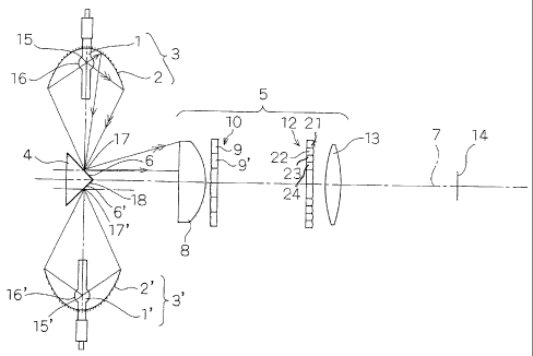
Figure 1 shows a schematic structure of the illumination
device in accordance with the embodiment of the present
invention.
The illumination device of this embodiment is
constituted by including: two lamp units 3 as an example
of plural light sources of the present invention which
include lamps 1 and ellipsoidal mirrors 2 serving as
condensing means; a triangular prism 4 as an example of
reflecting means of the present invention, a side 18 of
which is coated with a reflection film to form a synthesis
mirror 6 as an example of a reflection surface of the
present invention; a lens 8 which is arranged a
predetermined space apart from the prism 4 and changes
light beams, which are irradiated from the lamp units
CA 02482005 2004-10-06
- 25 -
3 and reflected on the synthesis mirror 6, to light beams
substantially parallel to an optical axis of an
illumination unit 5; a lens array 10 as an example of
a first lens array of the present invention which is set
a predetermined space apart from an outgoing side of the
lens 8 and has a shape with plural lenses 9 arranged in
a two-dimensional shape; a lens array 12 as an example
of a second lens array of the present invention which
is arranged a predetermined space apart from an outgoing
side of the lens array 10 and has a shape with plural
lenses arranged in a two-dimensional shape; a lens 13
which is arranged a predetermined space apart from an
outgoing side of the lens array 12 and is used for
irradiating a light beam emitted from the lens array 12
on a light-receiving surface; and a light-receiving
surface 14 which is arranged a predetermined space apart
from the lens 13 and is used for irradiating a light beam
emitted from the lens 13.
As the lamp 1, a very high pressure mercury lamp in
which a light-emitting material such as mercury or inert
gas is enclosed in a glass tube and a pressure in the
glass tube at the time of lighting rises to a very high
pressure or, other than the very high pressure mercury
lamp, a lamp such as a metal halide lamp, a xenon lamp,
CA 02482005 2004-10-06
- 26 -
or a halogen lamp excellent in light-emitting efficiency
is used.
A light-emitting portion 16 of the lamp 1 is arranged
in a first focus 15, which is one focus of the ellipsoidal
mirror 2 and condenses light irradiated from the lamp
1 on a second focus 17 side which is another focus of
the ellipsoidal mirror 2. A mirror surface of the
synthesis mirror 6 is arranged in the vicinity of the
second focus 17 of this ellipsoidal mirror 2 and can reflect
light emitted from the ellipsoidal mirror 2 in a direction
of the illumination unit 5. Similarly, light irradiated
from the lamp 1' of the other ellipsoidal mirror 2' , which
is arranged to be opposed to one ellipsoidal mirror 2,
is also condensed by the other ellipsoidal mirror 2' and
then reflected in a predetermined direction on a mirror
surface of the other synthesis mirror 6' of the prism
4. Consequently, the light irradiated from the two lamps
1 and 1' is made incident on the illumination unit 5 as
light beams traveling in substantially the same
direction.
The light emitted from the ellipsoidal mirrors 2 and
2' in the vicinity of the synthesis mirrors 6 and 6' is
condensed in small light source images in the vicinity
of the second focuses 17 and 17' and travels expanding
to the illumination unit 5 side with the vicinity of the
CA 02482005 2004-10-06
27 -
reflection surfaces of the synthesis mirrors 6 and 6'
as start points. The light traveling while expanding in
this way is made incident on the lens 8 and is converted
into light beams substantially parallel with the optical
axis 7 of the illumination unit 5 to exit from the lens
8.
The light beams having exited from the lens 8 are
guided into the plural lenses 9 of the lens array 10 and
divided into partial light beams. The divided respective
partial light beams are focused on the lens array 12,
which has lenses corresponding to the respective lenses
in the lens array 10, in shapes similar to apertures of
the respective lenses and superimposed one on top of
another on the light-receiving surface 14 serving as an
area, which should be illuminated, via the lens 13.
Consequently, although unevenness of brightness exists
in the light beams at the point when the light beams are
made incident on the lens array 10, the respective partial
light beams having various luminance distributions are
superimposed one on top of another, whereby illumination
with high uniformity is realized in the area which should
be illuminated.
The lens array 10 and the lens array 12 are arranged
a space apart from each other such that the partial light
beams divided by the lens array 10 are condensed in the
CA 02482005 2004-10-06
- 28 -
vicinity of the lens array 12. In addition, in the optical
system shown in Figure 1, since there is one light source
image formed on the synthesis mirrors 6 and 6',
respectively, the respective partial light beams
condensed by the respective lenses 9 also form two light
source images.
Therefore, light source images of a number, which
is found by multiplying the number of lenses 9 included
in the lens array 10 by the number of light source images
formed on the synthesis mirror 6 and the synthesis mirror
6', are formed on the lens array 12.
In the illumination device of the embodiment of the
present invention, lenses in the peripheral part among
the lenses of the lens array 12 are divided so as to
efficiently include the respective light source images.
In addition, as shown in Figure 1, the lenses 9' which
constitute the lens array 10, are arranged to be decentered
such that light source images are formed on the divided
lenses of the lens array 12. In other words, for example,
in the example shown in Figure 1, the lens 9' is decentered
such that two light source images from the lens 9 of the
lens array 10 are formed as light source images 27 and
29 on a lens 21, which is an example of a first lens of
the present invention, and a lens 23, which is an example
of a third lens of the present invention, of the lens
CA 02482005 2004-10-06
- 29 -
array 12, respectively, and two light source images from
the lens 9' separate from the lens 9 are formed as light
source images 28 and 30 on a lens 22, which is an example
of a second lens of the present invention, and a lens
24, which is an example of a fourth lens of the present
invention, of the lens array 12, respectively.
According to the related art, the light source image
corresponding to the lens 9 is formed on a lens 11 (a
lens having an area consisting of the lenses 21, 22 and
23 are assumed and called in this way) of the lens array
12, and the light source image corresponding to the lens
9' is formed on a lens 11' (a lens having an area consisting
of the lenses 22, 23 and 24 and not overlapping the area
of the lens 11 is assumed and called in this way) of the
lens array 12. The division of the lens array 12 means
that the lens 11 is divided into the lenses 21, 22 and
23 and the lens 11' is divided into the lenses 22, 23
and 24 as described above.
The lenses of the lens array 12 are divided in this
way to be arranged such that one light source image is
placed between the other light source images, whereby
an area of the peripheral part on the lens array 12 can
be reduced (e . g . , to 4/6) compared with the second lens
array 112 of the related art.
CA 02482005 2004-10-06
- 30 -
Such a concept of the lens division in the lens array
12 is illustrated more specifically in Figure 2 (a) and
(b). In short, as shown in Figures 2(a) and (b), the
apertures of the lenses in the peripheral part of the
lens array 12 are divided into the lens 21 and the lens
23, which are apertures corresponding to a light source
image from the predetermined lens 9 of the lens array
10, and the lens 22 and the lens 24, which are apertures
corresponding to a light source image from separate lens
9' other than the predetermined lens 9. Then, the lens
21, the lens 22, the lens 23, and the lens 24 are arranged
in this order. In addition, a center of curvature 25,
which is an example of a first center of curvature of
the present invention, of the lens 21 and the lens 23
and a center of curvature 26, which is an example of a
second center of curvature of the present invention, of
the lens 22 and the lens 24 are arranged to be adjacent
to but deviated from each other. In other words, a center
of curvature of the lens 21 and a center of curvature
of the lens 23 substantially agree with each other to
form the center of curvature 25, and a center of curvature
of the lens 22 and a center of curvature of the lens 24
substantially agree with each other to form the center
of curvature 26 . The center of curvature 25 and the center
CA 02482005 2004-10-06
- 31 -
of curvature 26 are arranged to be deviated from each
other.
The center of curvature 25 of the lenses 21 and 23
agrees with a center of curvature of the lens 11. In
addition, the center of curvature 26 of the lenses 22
and 24 agrees with a center of curvature of the lens 11' .
In other words, the centers of curvature of the lenses
11 and 11' are formed without being changed substantially
regardless of whether the lenses 11 and 11' are divided
or not (i.e., substantially preserved before and after
the division of the lenses 11 and 11') . In other words,
the centers of curvature 25 and 26, in the case in which
the lenses 11 and 11' are divided, are formed to agree
with the center of curvature in the case in which the
lenses 11 and 11' are not divided.
Figure 2(a) shows a plan view of such lenses 21 to
24 formed on the lens array 12, and Figure 2(b) shows
a sectional view thereof. With such a constitution,
individual light source images condensed by the lens 9
pass through the lenses 21 and 23 having the center of
curvature 25, and individual light source images
condensed by the lens 9' pass through the lenses 22 and
24 having the center of curvature 26. The light source
images are efficiently irradiated as effective light
= CA 02482005 2004-10-06
- 32 -
beams on the light-receiving surface 14 serving as an
area which should be illuminated.
In this way, the lenses in the peripheral part of
the lens array 12, in which a large gap tends to be formed
between a pair of light source images formed by the lens
9 of the lens array 10, are divided, and pairs of the
divided lenses have predetermined centers of curvature,
respectively. Thus, a gap between light source images
formed on the lens array 12 can be reduced, and the light
source images can be included more efficiently with a
small aperture than in the past.
For example, in the conventional illumination device,
the light source images 27 and 29 are focused in the area
formed of the lenses 21, 22 and 23 on the lens array 12,
and the light source images 28 and 30 are focused in the
area formed of the lenses 22, 23 and 24 which is an area
separate form the area in which the area of the lenses
21, 22 and 23 is formed. Therefore, when it is assumed
that areas of the lenses 21 to 24 are identical, in order
to focus a light source image from the predetermined lens
9 and a light source image from the separate lens 9' on
the lens array 12, an area equivalent to six lenses 21
is required.
However, according to the illumination device of the
present invention, with an area equal to four lenses 21,
CA 02482005 2004-10-06
- 33 -
a light source image from the predetermined lens 9 and
a light source image from the separate lens 9' can be
focused on the lens array 12. Therefore, it is possible
to cause an area, which can be saved in the peripheral
part of the lens array 12, to contribute to an increase
in apertures of the lenses in the central part of the
lens array 12. Alternatively, by reducing the area in
the peripheral part of the lens array 12 as described
above, an area of the entire lens array 12 can be made
smaller than the conventional irregular-shaped aperture
lenses, and miniaturization of the illumination device
itself can also be realized.
Note that the example shown in Figure 2 (a) and (b)
is an example. In particular, concerning the centers of
curvature 25 and 26, arrangements other than the
illustration are naturally conceivable.
In the illumination device of the present invention,
parts (gaps) on the lens array 12, where light source
images are not arranged, are eliminated as much as possible,
and a filling factor of light source images on the lens
array 12 is increased, whereby an illumination system
with higher efficiency can be realized by a smaller optical
system.
In this way, efficiency of the illumination device
can be improved more when the lenses arranged in the
CA 02482005 2004-10-06
- 34 -
peripheral part of the lens array 12 are divided and the
number of lenses of the lens array 12 is increased.
However, when the number of lenses of the lens array
12 is increased without any limitation, even if a light
source image formed by the separate lens 9' is moved to
between a pair of light source images formed in the central
part of the lens array 12, since a light source image
in the vicinity of the optical axis is large, there is
no gap between the pair of light source images, and there
is almost no place for arranging the new light source
image. In other words, on the lenses in the central part
of the lens array 12, most of light source images formed
by the separate lens 9' overlap the existing light source
images. In this case, since a position of a center of
curvature of the lenses has to be associated with one
of the lenses 9 and 91, any one of the light source images
in the overlapping part of the light source images does
not reach an area which should be illuminated, which leads
to a loss in terms of illumination efficiency.
Therefore, in order to obtain the above-described
effects more surely, the number of lenses NLA2 of the
lens array 12 only has to satisfy the following relation
with respect to the number of lenses NLA1 of the lens
array 10:
(Expression 2)
CA 02482005 2004-10-06
- 35
NLA1 < NLA2 < 2 x NLA1
Shapes of the lens array 10 and the lens array 12
may be any shapes as long as the above (expression 2)
is satisfied. As such an example, Figure 3 (a) shows an
example of a shape of the lens array 10 in the case in
which the number of the lenses 9 is forty-eight, and Figure
3(b) shows an example of a shape of the lens array 12,
which has sixty lenses, corresponding to the lens array
shown in Figure 3 (a) . In addition, Figure 3 (c) shows
an example of a shape of the lens array 10 in the case
in which the number of the lenses 9 of the lens array
10 is forty-two. Further, Figure 3 (d) shows an example
of a shape of the lens array 12, which has forty-six lenses,
corresponding to the lens array 10 shown in Figure 3 (c)
A part of the lenses of the lens array 12 is divided
in this way, whereby a size of the entire lens array 12
can be reduced to make the entire illumination device
small, or sizes of the apertures of the lenses in the
central part of the lens array 12 can be further increased
so much more for the reduction of a gap between the pair
of light source images formed in the peripheral part of
the lens array 12. Thus, it becomes possible to improve
efficiency of use of light.
Next, it will be explained, when at least one light
source image of a pair of light source images, which are
CA 02482005 2004-10-06
- 36 -
formed by the lens 9' separate from the predetermined
lens 9 of the lens array 10, is arranged between a pair
of light source images formed by the predetermined lens
9 of the lens array 10, which of the pair of light source
images formed by the separate lens 9' should be moved
to a gap between the pair of light source images formed
by the predetermined lens 9.
Figure 4 and Figure 5 show examples in which light
source images, which are actually formed in the peripheral
part of the lens array 12, are used. As shown in Figure
4, it is assumed that, in a pair of light source images
formed by the one predetermined lens 9, a width of a large
light source image on a straight line connecting area
centers of the respective light source images is R1, a
width of a smaller light source image is L1, and a width
of a gap between the light source images is G1, and
similarly, widths of a pair of light source images formed
by the separate lens 9 ' (i . e . , light source images which
would be originally formed on an imaginary lens 11' on
the lens array 12 corresponding to the lens 9' in the
case in which the lens 9' is assumed not to be decentered)
are R2 and L2, and a width of a gap between these light
source images is G2. In the case in which such two pairs
of light source images are combined, efficiency is better
when the images are arranged such that a rate of the width
CA 02482005 2004-10-06
37 -
(R1 or R2) of the large image with respect to the width
(Gi or G2) of the gap between the respective light source
images is as small as possible.
In other words, the arrangement among the respective
light source images only has to be determined such that
the following relation is satisfied:
(Expression 3)
R2/Gl >_ R1/G2
For example, in the examples shown in Figure 4 and
Figure 5, efficiency is better with a constitution in
which, rather than inserting a light source image 38 having
the width L2 in the gap of Gl or inserting a light source
image 37 having the width L1 in the gap of G2, a light
source image 39 having the large width R1 larger than
a light source image 40 having the width R2 is inserted
in the gap of G2 larger than Gl.
For example, Figure 5(a) two-dimensionally shows a
part of a structure of the lens array 12 in the case in
which the light source image 38 is arranged between the
light source images 37 and 39, and Fig 5 (b) shows a section
thereof. Although a lens 31 and a lens 33 are different
lenses, these lenses have an identical center of curvature
and are arranged across a lens 32. Further, although the
lens 32 and a lens 34 are different lenses, these lenses
have an identical center of curvature and are arranged
CA 02482005 2004-10-06
38 -
across the lens 33. In this case, the center of curvature
formed by the lenses 31 to 33 and the center of curvature
formed by the lenses 32 to 34 are arranged to be adjacent
to but deviated from each other.
However, even in the case in which the above-described
arrangement is not adopted, the same effect as described
above can be obtained in that efficiency can be made higher
than the conventional method and a size of the illumination
device can be reduced.
In addition, in the case in which a gap between a
pair of light source images is large, and a small light
source image formed by the separate lens 9' is inserted
in the gap between the light source images, a constitution
for inserting two or more pairs of light source images
formed by plural separate lenses 9' or the like rather
than a pair of light source images may be adopted. In
this case, again, the respective lenses after division
of the lens array 12 are arranged with positions of centers
of curvature thereof adjacent to but deviated from each
other in an area included in the lens 11, through which
the pair of light source images pass, such that light
beams from the corresponding lenses 9 and 9' or the like
become effective illumination reaching an area which
should be illuminated. In addition, the lenses 9 and 9'
or the like are arranged to be decentered such that light
CA 02482005 2004-10-06
- 39 -
beams passing through the lenses or the like are condensed
by the lens 11.
For example, Figure 6(a) shows, as a plan view, a
part of a structure of the lens array 12 in the case in
which a light source image 51 and a light source image
52 are arranged between light source images 50 and 53,
and Figure 6 (b) shows a section thereof. In this case,
a center of curvature 47 is formed by lenses 41 to 44,
a center of curvature 48 is formed by lenses 42 to 45,
and a center of curvature 49 is formed by lenses 43 to
46. The centers of curvature 47, 48 and 49 are arranged
to be adjacent to but deviated from each other.
In other words, a center of curvature of the lens
41 and a center of curvature of the lens 44 substantially
agree with each other to form the center of curvature
47, a center of curvature of the lens 42 and a center
of curvature of the lens 45 substantially agree with each
other to form the center of curvature 48, and a center
of curvature of the lens 43 and a center of curvature
of the lens 46 substantially agree with each other to
form the center of curvature 49. The centers of curvature
47 , 48 and 49 are arranged to be deviated from each other.
However, the respective centers of curvature are formed
without change regardless of whether the lens 11 is divided
or not as in the case shown in Figures 2(a) and (b).
CA 02482005 2004-10-06
- 40 -
In this way, the lens array 10 and the lens array
12 are formed so as to fill a gap between light source
images with another light source image as much as possible,
whereby a distance among the respective centers of
curvature formed on the predetermined lens 11 on the lens
array 12 can be reduced. Therefore, in that case, the
size of the entire lens array 12 can be further reduced,
or a diameter in the central part of the lens array 12
can be increased, whereby efficiency of use of light can
be improved.
In addition, as shown in Figure 7, in the lenses after
division of the lens array 12, in the case in which one
pair of light source images among two pairs of light source
images are relatively small and do not contribute to
overall efficiency of use of light significantly, the
lens 11 may be constituted by three or two of four lenses
11.
As described above, according to the present
invention, the lens array 12 is divided to be smaller
than the lens array 10, whereby gap areas, which are
generated among plural light source images formed on the
lens array 12, can be reduced, and an illumination device
with high efficiency of use of light can be obtained.
In addition, if the illumination device of the present
CA 02482005 2004-10-06
- 41 -
invention is used, a projection display device with high
efficiency of use of light can be realized.
Note that outward forms, which are illustrated for
representing sizes of light source images shown in Figures
12 and 2 (a) , are indicated by equi-luminance lines having
luminance of 10 to 30% in the case in which a maximum
luminance in the light source image is assumed to be 100%.
Such equi-luminance lines are indicators indicating a
range in which efficiency of use of light is affected
by taking in light as a light source image in the aperture
of the lens 11. Thus, by the above formation of the lens
arrays 10 and 12 in the case in which all the outward
forms of these equi-luminance lines are contained in the
lens 11, a significant effect can be obtained by using
the above-described method. However, even in the case
in which the outward forms of the equi-luminance lines
partly overlap each other, or even in the case in which
a part of the outward forms of the equi-luminance lines
bulges out from the lens 11, it is possible that effects
such as improvement of efficiency and reduction in a size
of the lens array 12 can be obtained as the optical system
as a whole.
In addition, a gap or a space between plural light
source images in the above description have been
represented as a distance from one equi-luminance line
CA 02482005 2004-10-06
42 -
to another equi-luminance line on a line connecting area
centers of images surrounded by the equi-luminance lines.
However, the space between the light source images may
be defined by other methods.
Further, in the above description, the triangular
prism 4 having the synthesis mirrors 6 and 6' , the sides
of which are coated with a reflective film, is described
as the reflecting means of the present invention. However,
the reflecting means of the present invention is not
limited to the prism 4 but may be a structure using two
mirrors and may be any structure as long as the structure
reflects light beams irradiated from two light sources
to the illumination unit 5.
Moreover, in the above description, the example of
using the ellipsoidal mirror 2 as the condensing means
is described. However, the condensing means may be a
parabolic mirror. Furthermore, it is also conceivable
that a lens is used as the condensing means. In that case ,
since a size of a light source image does not change
significantly in the central part and the peripheral part
of the second lens array 12, a shape of the lens array
12 is not required to be irregular-shaped apertures.
Further, in the case in which light source images formed
on predetermined one lens 11 on the lens array 12 are
spaced apart from each other, a constitution may be adopted
CA 02482005 2004-10-06
- 43 -
in which a light source image, which is formed by the
lens 9' separate from the predetermined lens 9
corresponding to the predetermined lens 11, is formed
between light source images which are formed on the
predetermined lens 11 in the same manner as described
above. In such a case, the same effect as described above
can be obtained.
In addition, in Figure 1, behind the lens array 12,
the lens 13 is illustrated as the optical means of matching
light to a shape of the light-receiving surface 14 side,
which should be illuminated, and converting the light
into illumination light having uniformity. However, as
a structure of the illumination device of the present
invention, the illumination device may have a structure
without the lens 13, a structure in which plural single
lenses are combined, or a structure of an optical system
in which optical elements such as a mirror and a prism
are included.
Further, in the above-described illumination device,
as shown in Figure 8, if a liquid crystal panel 61 (optical
modulation device) of a transmission type and a prof ection
lens 62 are provided as an example of the display device
of the present invention, a proj ection display apparatus,
which can provide a proj ection image with high uniformity,
can be obtained.
CA 02482005 2004-10-06
44 -
Moreover, in Figure 8, a structure including only
one liquid crystal panel 61 as an optical modulation device
is illustrated. However, a structure including plural
optical modulation devices may be adopted. In addition,
instead of the liquid crystal panel 61 of the transmission
type, a transmission light bulb, a reflection light bulb,
a mirror panel which can change a direction of reflection
with a micro-mirror arranged in array, an optical
modulation device of an optical writing system, an image
display device, or the like can be used. Moreover, it
is conceivable that the display device of the present
invention is, for example, a sheet for an OHP.
Further, in Figure 1, the structure using the two
light sources is illustrated. However, a structure using
three or more light sources may be adopted. However, in
the case in which three or more (N) light sources are
used, the number of lenses NLA2 of the lens array 12 only
has to satisfy the following relation with respect to
the number of lenses 9 NLA1 of he lens array 10:
(Expression 4)
NLA1 < NLA2 < N x NLA1
In that case, the structure only has to be a structure
in which the lens array 10 is formed such that, in a first
predetermined space which is a largest space among plural
images formed on the lens array 12 by the predetermined
CA 02482005 2004-10-06
- 45 -
lens 9 of the lens array 10, a largest image among images
formed on the lens array 12 a second predetermined space,
which is smaller than the first predetermined space, apart
from each other by the lens 9' separate from the
predetermined lens 9 of the lens array 10 is formed.
Moreover, although not shown in the figure, a
structure using a prism, a filter, a mirror, or the like,
which can perform color separation and color composition,
may be adopted.
Industrial Applicability
According to the illumination device and the
illumination method in accordance with the present
invention, efficiency of use of plural light sources can
be improved. Thus, the illumination device and the
illumination method are useful in a projection display
apparatus and the like.