Note: Descriptions are shown in the official language in which they were submitted.
CA 02482222 2004-09-21
#237185
DIRECT-VENT FIREPLACE CONFIGURABLE
FOR TOP VENTING OR REAR VENTING
BACKGROUND OF THE INVENTION
The present invention relates in general to fireplace structures and, in
particular, to
direct-vent, gas fireplace structures. More specifically, the present
invention relates to a
direct-vent fireplace that may be configured in one arrangement for top
venting and, in
an alternate arrangement, for rear venting. The alternate arrangements are
enabled by the
combination of an inlet cover plate and outlet elbow. The arrangement of this
inlet cover
plate and outlet elbow relative to the remainder of the fireplace structure
determines
whether the fireplace will be a top venting unit or a rear venting unit.
U.S. Patent No. 6,295,981 issued October 2, 2001 to Beal et al. addresses a
problem associated with some direct-vent, gas fireplaces namely, the
difficulty in
selectively and easily venting combustion gases in either a horizontal or a
vertical
direction. In the context of the present invention, the horizontal direction
would
correspond to a rear vent arrangement while the vertical direction would
correspond to a
top vent arrangement. The `981 patent explains some of the realities of
conventional
fireplace designs and discusses some of the efforts of other designers
(inventors) in the
following manner.
Gas fireplaces of conventional design typically utilize a source of combustion
air
from the room being heated. This lowers the efficiency of the gas fireplace
because a
portion of the heated air in the room is drawn into the combustion chamber and
exhausted up the chimney. It is known to provide separate ducting from the
outside
ambient environment to the combustion chamber to increase the efficiency of
the
fireplace. The ducted air provides a source of oxygen for combustion in the
combustion
chamber and decreases the amount of air from the room being heated which is
exhausted
up the chimney. Such ducting, however, requires additional materials and labor
to
install.
CA 02482222 2004-09-21
2
It is also known in the art to utilize concentric flue pipes to exhaust
combustion
products to the outside environment and supply combustion air from the outside
environment. Such fireplaces are termed "direct-vent" fireplaces and are
disclosed, for
example, in U.S. Patent No. 4,793,322 (Shimek I) and U.S. Patent No. 4,909,227
(Rieger). A direct-vent fireplace has the advantage of utilizing a common
concentric flue
pipe assembly to both exhaust combustion products from and supply combustion
air to
the combustion chamber. Moreover, only a single opening need be cut through an
exterior wall of a house to accommodate the concentric flue pipe assembly.
In general, a direct-vent fireplace has a first pipe with a diameter larger
than and
disposed concentrically around a second pipe. The duct formed by the second
pipe is
used to convey exhaust products from the combustion chamber to the outside
environment. The annular space formed between the first and second pipes
defines a
fresh air conduit through which combustion air flows from the outside ambient
environment into the combustion chamber.
A problem with direct-vent gas fireplaces is that the concentric flue pipe
assembly
cannot be easily vented in both a horizontal or vertical direction. Shimek I
and Rieger
disclose direct-vent fireplaces which respectively connect the concentric flue
to the rear
wall and top wall of the fireplace. A concentric flue attached to the rear
wall of the
fireplace maybe easily extended through an adjacent sidewall of the house.
However, if
it is desirable to exhaust the concentric flue in a vertical direction, the
fireplace must be
moved forward a sufficient distance to allow coupling of a right angle
concentric pipe
elbow. Thus, additional floor space is required to accommodate the projected
footprint
of the fireplace and concentric flue pipe assembly.
A concentric flue pipe assembly attached to the top of a direct-vent fireplace
has a
similar problem when it is desired to vent the concentric fluid in a
horizontal direction
(see, e.g., Rieger at Col. 1, lines 23-32). That is, the fireplace must be
moved forward a
sufficient distance to allow coupling of a right angle concentric pipe elbow.
Because of two possible installation configurations, i.e., vertical or
horizontal
venting of the concentric flue pipe assembly, it is necessary with
conventional direct-
vent fireplaces to provide two totally different configurations. That is, for
relatively
close placement of the fireplace adjacent the outside wall of the house, it is
necessary to
provide one configuration allowing attachment of the concentric flue pipe
assembly to
CA 02482222 2004-09-21
3
the back of the fireplace for horizontal venting, and a second configuration
allowing
attachment of the concentric flue pipe assembly to the top of the fireplace
for vertical
venting. The necessity to provide two different configurations increases
inventory
requirements at the factory. Reference can be made, for instance, to U.S.
Patent No.
5,320,086 (Shimek II) regarding the same. Shimek H is directed to a single
fireplace
construction that could be used in both a vertical venting configuration
(i.e., relatively
straight upwardly from the fireplace) of a horizontal venting configuration
(i.e., relatively
straight out from the back of the fireplace).
Moreover, such fireplaces should be equipped with a mechanism or process that
enables one type of venting (e.g., vertical), while preventing the other type
of venting
(e.g., horizontal). This would allow any exhaust matter to escape the
fireplace via the
selected venting type, while preventing the same from escaping via the non-
selected
type.
Accordingly, it would be desirable to have a fireplace that overcomes the
above
disadvantages.
The perceived improvement offered by the `981 patent is to first provide both
a top
port (40) and a rear port (41). These two ports communicate with an outlet box
(44)
extending from the combustion chamber (11). Each port includes a bottom panel
(48)
defining a circular hole (49). Next, according to the `981 patent, an air
inlet pipe
member (60) and a separate air outlet pipe member (61) are provided. Included
as part
of outlet pipe member (61) is a plate portion (63) that attaches to the bottom
panel (48).
Inlet pipe member (60) then is assembled in a concentric manner relative to
outlet pipe
member (61). Inlet pipe member (60) includes an integral cover plate portion
(67) that
functions to close off the non-selected port.
The present invention discloses a structural configuration that enables
selective
fireplace conversion to either horizontal (rear) venting or vertical (top)
venting. Rather
than using an outlet pipe member with a cumbersome plate portion, the present
invention
uses two separate cover plates. The fireplace is configured with an inner
panel set at
approximately 45 degrees relative to the horizontal and vertical directions
and defines a
vent port that is in direct flow communication with the combustion chamber.
One
feature of the present invention is the use of an outlet elbow. One of the
unexpected
benefits of this design is an increase in velocity of the heated gas exiting
the combustion
CA 02482222 2004-09-21
4
chamber. This increase in velocity in turn increases the intake air flow
thereby
increasing the heat output and flame performance of the fireplace. Moreover,
this
structure provides the ability to attach the inlet/outlet subassembly in a
first orientation or
arrangement for vertical venting and in a second orientation or arrangement
for
horizontal venting, while using the same vent port.
The convenience and simplicity of this structure, according to the present
invention, is seen as a novel and unobvious advance in the art.
CA 02482222 2004-09-21
SUMMARY OF THE INVENTION
A direct-vent fireplace configurable into a top venting unit in one
arrangement and
configurable into a rear venting unit in another arrangement according to one
embodiment of the present invention comprises a combustion chamber, an outer
enclosure enclosing at least a portion of a combustion chamber, the outer
enclosure
including a rear panel defining a rear opening and including a top panel
defining a top
opening, a vent panel positioned between the combustion chamber and the outer
enclosure, an outlet elbow attached to the vent panel and arranged in flow
communication with the combustion chamber, and an inlet cover plate
surrounding a
portion of the outlet elbow that extends through the outer enclosure, wherein
the outlet
elbow portion extends through the rear opening for achieving the rear venting
arrangement and the outlet/elbow portion extends through the top opening for
achieving
the top venting arrangement.
One object of the present invention is to provide an improved direct-vent
fireplace.
Related objects and advantages of the present invention will be apparent from
the
following description.
CA 02482222 2004-09-21
6
BRIEF DESCRIPTION OF THE DRAWINGS
FIG. 1 is a diagrammatic, perspective view of a direct-vent, gas fireplace,
without
its outer enclosure, according to a typical embodiment of the present
invention.
FIG. 2 is a diagrammatic, front elevational view of a fireplace assembly based
in
part on the FIG. 1 fireplace.
FIG. 3 is a diagrammatic, side elevational view, in full section,
corresponding to
the FIG. 2 fireplace arrangement.
FIG. 4 is a diagrammatic, top plan view of the FIG. 2 fireplace arrangement.
FIG. 5 is a diagrammatic, front elevational view of a fireplace assembly based
in
part on the FIG. 1 fireplace.
FIG. 6 is a diagrammatic, side elevational view, in full section,
corresponding to
the FIG. 5 fireplace arrangement.
FIG. 7 is a diagrammatic, top plan view of the FIG. 2 fireplace arrangement.
FIG. 8 is an exploded view of a direct-vent, gas fireplace, without its outer
enclosure, depicting the attachment of the outlet elbow.
FIG. 9 is a partially exploded view of the FIG. 8 fireplace assembly with
enclosing
panels included, depicting the attachment of cover plates to the enclosing
panels.
FIG. 10 is a partially exploded view of the FIGS. 8 and 9 fireplace assembly,
with
an outer enclosure added.
CA 02482222 2004-09-21
7
DESCRIPTION OF THE PREFERRED EMBODIMENTS
For the purposes of promoting an understanding of the principles of the
invention,
reference will now be made to the embodiments illustrated in the drawings and
specific
language will be used to describe the same. It will nevertheless be understood
that no
limitation of the scope of the invention is thereby intended, such alterations
and further
modifications in the illustrated device, and such further applications of the
principles of
the invention as illustrated therein being contemplated as would normally
occur to one
skilled in the art to which the invention relates.
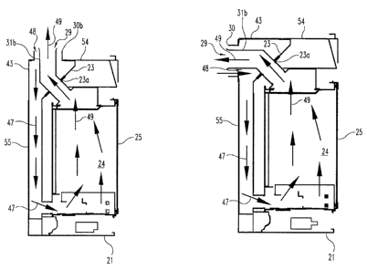
Referring to FIG. 1, there is illustrated a gas fireplace 20 that is
constructed and
arranged for direct-venting of combustion gases. Fireplace 20 is
diagrammatically
illustrated and includes various sheet metal panels that provide, among other
structural
components, a base 21, rear panel 22, and vent panel 23. A combination of
sheet metal
panels are constructed and arranged in order to create the illustrated
fireplace combustion
chamber 24. The front wall 25 of the fireplace 20 is typically a combination
of metal
and glass, serving both decorative and performance functions. The actual
construction
details regarding the front wall 25, base 21, and combustion chamber 24 are
considered
to be secondary to the primary points of focus of the present invention.
Accordingly, a
majority of the discussion regarding the present invention is directed to rear
panel 22 and
vent panel 23, as well as to the outer enclosure 28 that cooperates with
fireplace 20 in
order to create a fireplace assembly 32. Two slightly different fireplace
assemblies or
arrangements are illustrated according to the present invention. A top or
vertical venting
arrangement is diagrammatically illustrated in FIGS. 2-4. A rear or horizontal
venting
arrangement is diagrammatically illustrated in FIGS. 5-7. The partially
exploded views
of FIGS. 8, 9 and 10 illustrate the sequential build up of panels to complete
the fireplace
assembly 32 for a rear venting arrangement. In both the top venting and rear
venting
arrangements, it will be noted that vent panel 23 remains in the same
assembled location
and orientation with an approximate 45 degree incline relative to horizontal
and vertical
directions. Anticipating a normal or conventional fireplace installation, it
would be
expected for the front wall 25 of the fireplace to be substantially vertical
and
substantially parallel to the rear panel 38 of the outer enclosure 28.
Likewise, it would
CA 02482222 2004-09-21
8
be expected that the base 21 would be positioned so as to be substantially
horizontal and
substantially parallel to the top panel 36 of the outer enclosure 28.
The primary focus of the present invention is directed to a cooperating
combination of an inlet component (cover plate) 30 and an outlet component
(outlet
elbow) 31, referred herein as "subassembly" 29. More specifically, the focus
of the
present invention is directed to the options for attaching the outlet elbow 31
to vent panel
23. The inlet and outlet components work together as an unit and as part of
the fireplace
assembly 32 that includes fireplace 20, interior sheet metal panels and outer
enclosure
28. Since the fireplace assembly 32 includes the same grouping of component
parts,
albeit in two different arrangements, reference number 32 is used for both
arrangements.
As is illustrated, the inlet cover plate 30 includes a mounting plate 30a and
an integral
cylindrical sleeve 30b. The outlet elbow 31 includes a mounting plate 31a and
an
integral elbow conduit 31b, having an approximate 45 degree bend (i.e., 135
degree
included angle).
Vent panel 23 is positioned between the combustion chamber 24 and the outer
enclosure 28. The vent panel 23 is angled approximately 45 degrees relative to
the top
panel 36 and rear panel 38. This orientation represents the normal or expected
orientation for the fireplace assembly 32 within the structure where it will
be installed.
Vent panel 23 includes a generally square opening 23a that is constructed and
arranged to receive mounting plate 31a of outlet elbow 31. The specific style
of
attachment is not critical so long as plate 31a closes off opening 23a, except
for the
venting of combustion gas by way of conduit alb. One or more removable
fasteners 34
are used to secure plate 31a to vent panel 23.
In the FIG. 1 illustration, the mounting plate 31a of subassembly 29 is
attached
directly to vent panel 23 for the venting of combustion gas from the rear of
the fireplace
assembly 32 (see FIGS. 5-7). By turning the outlet elbow 31 180 degrees, the
fireplace
assembly 32 is configured for the venting of combustion gas from the top of
the fireplace
assembly 32 (see FIGS. 2-4). Regardless of how the fireplace assembly 32 may
be
initially configured for the intended installation, it can be readily changed
to the other
configuration or arrangement by simply removing the fasteners 34, turning the
mounting
plate 31a 180 degrees, and reinserting the removable fasteners 34. This change
in
configuration not only changes the fireplace assembly 32 from a rear vent
arrangement to
CA 02482222 2004-09-21
9
a top vent arrangement (or vice versa), but it also changes where the mounting
plate 30a
of the inlet cover plate 30 should be affixed. Additionally, this change in
arrangement
changes which portion of the outer enclosure, either the rear panel 38 or the
top panel 36,
is used for exhausting of the combustion gases.
The fireplace assembly 32 includes, in combination, the fireplace 20, interior
panels 54 and 55, the outer enclosure 28, and the inlet/outlet subassembly 29.
The
arrangement of these components and subassemblies is diagrammatically
illustrated in
FIGS. 2-7 and as partially exploded views in FIGS. 8-10. As illustrated, the
outer
enclosure 28 includes an opening 35 in top panel 36 and there is a similarly
sized and
shaped opening 37 in rear panel 38. The FIG. 1 configuration for fireplace 20,
corresponding to FIGS. 5-7 and 8-10, positions the mounting plate 30a of inlet
cover
plate 30 on the intermediate panel 55 at a location (opening 55a) that is
aligned with
opening 37. The arrangement corresponding to FIGS. 2-4 positions the mounting
plate
30a of inlet cover plate 30 on the intermediate panel 54 at a location
(opening 54a) that is
aligned with opening 35. In FIG. 4, plate 30a includes a plurality of
peripheral mounting
(clearance) holes 39 and a cooperating series of internally-threaded inserts
40 (or
captured nuts) that are located in panel 54 around the periphery of opening
54a. A
generally concentric relationship is maintained between the conduit 31b of
outlet elbow
31 and the cylindrical sleeve 30b of inlet cover plate 30.
With continued reference to FIG. 4, the disclosed design allows mounting plate
30a to be positioned through opening 35 and attached to panel 54 by the use of
threaded
fasteners 59 extending through clearance holes 39 and received by threaded
inserts 40.
This leaves opening 55a uncovered and, in order to close off this opening and
complete
fireplace assembly 32, a cover plate 43 is used and is attached to panel 55 in
the same
way that plate 30a is attached to panel 54. In fact, as will be clear, not
only are the size
and shape of openings 54a and 55a virtually identical, but the number,
location, and
spacing of the internally-threaded inserts 40 associated with both openings
are virtually
identical. Openings 35 and 37 are slightly larger than openings 54a and 55a
and are
aligned respectively. This means that plate 30a can either be positioned over
opening
55a and attached to panel 55 or positioned over opening 54a and attached to
panel 54.
Likewise, cover plate 43 can either be positioned over opening 54a and
attached to panel
CA 02482222 2004-09-21
54 or positioned over opening 55a and attached to panel 55. It is intended
that the
inlet/outlet subassembly 29 and cover plate 43 will be used together.
From the diagrammatic illustrations of FIGS. 3 and 6, it will be seen that the
incoming combustion air is represented by arrows 47 and this air flows through
the
generally annular ring corridor 48 defined by the concentric arrangement of
conduit alb
and sleeve 30b. The combustion gases (combustion by-products) are exhausted
from the
combustion chamber 24 by way of subassembly 29 as represented by flow arrows
49.
Ambient air enters through annular ring corridor 48 as combustion by-products
exit as
represented by flow arrows 47. The exit velocity of the combustion gases
(combustion
10 by-products) is increased through the arrangement of subassembly 29 and the
vent panel
23 creating an initially angled exit of combustion gases through outlet elbow
31. The
exit velocity of the hot gases is increased because of a vertical velocity
component. The
initial angled exit allows the exit velocity to overcome any resistance
created at the
elbow.
In the exploded views of FIGS. 8-10, it is better seen how subassembly 29 is
composed and combined with the intermediate panels 54 and 55 and with outer
enclosure
28. Outlet elbow 31 is attached to vent panel 23 by covering the opening 23a
with the
mounting plate 31a. Mounting plate 31a is firmly affixed to panel 23 by
passing
threaded fasteners 34 through clearance holes 51 in mounting plate 31a and
into holes 52
in panel 23. The fasteners 34 are preferably of a type that allows easy
insertion and
removal in light of the difficulty for an user to manually work with the
threaded end
during insertion. It is envisioned that a captured nut or threaded insert will
be used in
holes 52 to receive fasteners 34. The outlet elbow 31 is positioned in FIG. 8
for venting
of combustion gas from the rear of the fireplace assembly 32. The vent plate
23 is
positioned approximately 45 degrees in relation to the intermediate panels 54
and 55,
top enclosure panel 36, and rear panel 38. The outlet elbow bends
approximately 45
degrees to provide an initial angled exit for the exhaust gas and either a
vertical or
horizontal final exit from the fireplace assembly 32. As mentioned earlier,
this
arrangement adds a vertical velocity component for the gases during the
initial angled
exit thereby improving air intake and heat output.
Beginning with the FIG. 8 fireplace subassembly, the next step or layer in the
fabrication process is the addition of intermediate sheet metal panels 54 and
55 (see FIG.
CA 02482222 2011-08-11
61211-1827
9). These two panels are horizontal and vertical and are securely joined
together and to
the remainder of the FIG. 8 structure. Additional sheet metal panels may be
utilized as
part of this overall fabrication process in order to construct a strong and
secure fireplace.
However, with regard to the present invention, the focus will be on the use of
the top
(intermediate) panel 54 and the rear (intermediate) panel 55.
Top panel 54 includes opening 54a that is either closed by cover plate 43
using
threaded fasteners 59 (as illustrated) or receives inlet cover plate 30 when a
top venting
arrangement is selected. Rear panel 55 includes opening 55a that either
receives inlet
cover plate 30 by using threaded fasteners 59 (as illustrated) or receives
cover plate 43
when a top venting arrangement is selected.
Referring to FIG. 10, the outer enclosure 28 is added to the FIG. 9 structure
so as
to enclose the fireplace assembly and the intermediate panels. Included as
part of
enclosure 28 are top panel 36 and rear panel 38. Panel 36 includes opening 35
that is
aligned with opening 54a. Panel 38 includes opening 37 that is aligned with
opening
55a. The larger opening size for openings 35 and 37 allows the threaded
fasteners used
for inlet cover plate 30 and for outlet elbow 31 to remain accessible without
having to
remove the outer enclosure. Depending on the venting arrangement selected, the
conduit
31b of the outlet elbow 31 extends through the corresponding panels, either
panels 54
and 36 for top venting or panels 55 and 38 for rear venting.