Note: Descriptions are shown in the official language in which they were submitted.
' ~ CA 02482319 2004-10-12
I
Folding top for a cabriolet vehicle
s The invention relates to a folding top for a cabriolet vehicle according to
the
preamble of claim 1 and/or 17.
The modern construction of folding cabriolet tops which consists of a
plurality of
solid roof parts, and can be stowed automatically in a rear region of the
vehicle,
io is generally accompanied by the problem of rigid parts which can be moved
extensively in relation to one another. In respect of the configuration of the
relative sizes of the roof parts, of the movement sequence of the roof parts
in
relation to one another, of the dimensions of the collapsed and stowed roof
and
of the outlay in relation to the drive devices which are to be provided, in
terms
is of the number and associated costs thereof, a set of simultaneously
fulfillable
boundary conditions is often desirable. Thus, in the case of a number of
particularly preferred embodiments of multi-part hard-shell tops, the
overlapping
of the movements of different roof parts in space results, for example, in it
only
being possible for these roof parts to be pivoted sequentially, or quasi-
2o sequentially, without colliding with one another.
It is known, from the construction of hard-shell tops, to provide separate
drive
devices for different roof parts in order to achieve sequential pivoting of
the
different roof parts in each case.
In order to release a stowage space for the folding top in the rear region
during
an opening movement, use is often made of a rear element which can be
pivoted open counter to the direction of travel, possibly for a rear-window
shelf
arranged in front of the rear element being provided in a separately pivotable
manner in order to achieve a collision-free movement sequence. The pivoting of
the rear-window shelf here allows the rear roof part to move into the stowage
space.
CA 02482319 2004-10-12
' 2
DE 44 35 222 C1 describes a folding top in which the rear roof part is pivoted
open, in the first instance, in the direction of travel, whereupon the rear
element
can be opened counter to the direction of travel without a separately
pivotable
s rear-window shelf necessarily having to be provided. The disadvantage with
the
solution presented here is that both the rear roof part and a central roof
part,
which adjoins the rear roof part in the direction of travel, are articulated
separately in each case on the bodywork of the vehicle. In order not to
collide
with the central roof part during pivoting in the direction of travel, the
io articulations of the rear roof part comprise extendable hydraulic cylinders
in
order to raise the rear roof part over the central roof part. Such activation
is not
just complex and costly, but also susceptible to malfunctioning. In addition,
it is
necessary to have further means for fixing the rear roof part when the folding
top is closed since the hydraulic cylinders which, at the same time, form
bearing
is links of the roof part, are not readily routed in their longitudinal
direction. In
order to do away with an even greater number of drive arrangements, it is
proposed to lock the rear roof part to the central roof part in a position in
which
it has been pivoted over the central roof part. In respect of automated
folding-
top opening, however, it is also necessary to have high-outlay hydraulic or
2o electromechanical means for this purpose.
DE 100 06 296 C1 describes a three-part hard-shell top for a cabriolet vehicle
in which a central roof part is connected to a bodywork of the vehicle by
means
of a link mechanism, both a front roof part and a rear roof part being mounted
2s on the central roof part in each case via link mechanisms, and it being
possible
for the front roof part to be moved over the central roof part and for the
rear roof
part to be moved beneath the front roof part and over the central roof part.
Such an arrangement provides for unfavorable stacking of the roof parts and,
if
at all, can only be realized in the manner presented, with essentially planar
roof
3o parts. If, for example, the rear roof part comprises C-pillars of the
vehicle, or if
the roof parts are to be stacked in a different order, then the technical
realization quickly comes up against limitations, at least when as large a
. CA 02482319 2004-10-12
3
proportion of the roof-part movements as possible take place in a positively
controlled manner in relation to one another.
The object of the present invention is to provide a folding top for a
cabriolet
s vehicle according to the preamble of claim 1 and/or claim 17 in the case of
which the flexibility of the positively controlled movement of roof parts in
relation
to one another is increased.
This object is achieved according to the invention, for a folding top for a
io cabriolet vehicle which is mentioned in the introduction and is in
accordance
with the preamble of claim 1, by the characterizing features of claim 1.
A mechanical control device is advantageously provided here in a positively
controlled connection of a first and a second roof part, with the result, that
on
Is the one hand, the roof parts can be moved simultaneously by means of just a
single drive device and, on the other hand, the mechanical control device
allows coordination of the movement of the roof parts, in particular a
temporal
sequential or quasi-sequential sequence of the individual movements without
any additional drives being required. In particular, doing away with
additional
2o drives, in addition to reducing costs, ensures that the mechanics of the
folding
top as a whole are less susceptible to malfunctioning.
A folding top according to the invention additionally achieves the situation
where an opening movement of a front or central roof part can begin before the
2s first roof part has moved all the way over the front or central roof part,
with the
result that a particularly time-saving opening movement can be realized
overall.
In a preferred embodiment of a folding top according to the invention, the
control device comprises a rotary link. A single force-introduction unit
3o particularly preferably drives the rotary link, and the rotary link is
connected to
the first roof part via a first linkage and to the second roof part via a
second
linkage. It is thus possible to transmit a given way of the force-introduction
unit
in accordance with the principle of a projected circular movement onto the
first
CA 02482319 2004-10-12
4
and the second linkages, with a phase shift in each case. Starting from a
closed
folding-top position, it is thus possible to drive, in the first instance, the
first
linkage and thus the first roof part, whereas the second linkage, and thus the
second roof part, is noticeably driven only once the rotary link has been
rotated.
s If the angular position alpha of the rotary link in the starting position is
called
zero degrees, then, in a first approximation, it is possible for a factor
which can
be achieved in the transmission of the displacement for the first linkage to
be
proportional to sine (alpha + delta) and for the factor. for the transmission
of the
displacement of the second linkage to be proportional to sine
io (alpha + delta + phi), where the phase shift phi is preferably in the order
of
magnitude of ninety degrees and delta is a constant, predetermined angle of
origin. Delta can preferably differ from zero and, in particular, be somewhat
smaller than zero, in order that there is a large transmission factor for the
first
linkage for as long as possible at the start of the movement operation.
is
The first roof part is particularly preferably a front roof part, and the
second roof
part is a rear roof part, of the folding top, a central roof part being
arranged
between the first roof part and the second roof part when the folding top is
closed. It is preferable here for the first roof part to be connected to the
central
2o roof part via a front four-bar mechanism, and for the second roof part to
be
connected to the central roof part via a rear four-bar mechanism.
In particular in the case of the first roof part moving in the opposite
direction in
relation to the second roof part here, this movement, in addition, being
particularly extensive as a result of the four-bar mechanisms, the fact that
the
2s invention provides the mechanical control device is advantageous since this
makes it possible to achieve a particularly large degree of freedom in the
dimensioning of the roof parts and the design of the paths of motion of the
roof
parts.
3o The central roof part may advantageously be connected to the bodywork of
the
vehicle via a main four-bar mechanism, with the result that, during or after
pivoting of the first and of the second roof parts over the central roof part,
it is
w CA 02482319 2004-10-12
' 5
possible for the roof parts arranged in a stack to be pivoted together into a
rear
stowage region by means of the main four-bar mechanism.
At least one link of the front four-bar mechanism particularly advantageously
is
s arranged adjacent the outside of the central roof part when the folding top
is
closed. This advantageously achieves the situation, in respect of space-saving
stowage of the open folding top, where a link which bears the means for
activating the first, front roof part may be of particularly short
configuration,
since the outside link of the front four-bar mechanism allows the front four-
bar
io mechanism to be largely set back relative to the central roof part. In
particular,
however, this provision of the outside link also results in very advantageous
use
of the control device, since the outside link ultimately gives rise to
particularly
space-consuming pivoting of the first roof part which, without the control
device,
would, in the case of a preferred folding top, result in a collision with the
is second, rear roof part.
The object of the invention is additionally achieved, for a folding top which
is
mentioned in the introduction and is in accordance with the preamble of
claim 17, by the characterizing features of claim 17.
Mounting the roof parts according to the invention on a common main-link
mechanism which can be moved in relation to the bodywork of the vehicle
advantageously provides a folding top which, as far as the rest of its
configuration is concerned, has a particularly high level of flexibility. On
account
2s of the possibility of providing a rear-window shelf, or covering for a rear-
passenger compartment region located beneath the folding top, which is
formed integrally with the rear element, it is possible to dispense with an
otherwise necessary, high-outlay operation of pivoting the rear-window-shelf
region separately.
The second roof part advantageously rests on the rear element with sealing
action from above when the folding top is closed and, in a first stage of a
folding-top opening movement, can be raised up from the rear element, with the
~
CA 02482319 2004-10-12
6
result that, on the one hand, straightforward sealing of the folding top in
its rear
region is made possible and, on the other hand, it is possible to utilize
early
release of the rear element for simultaneous movement of the folding-top parts
and of the rear element. The rear element can be pivoted open counter to the
s direction of travel in a particularly straightforward manner here in order
to
release a rear stowage region for the folding top.
In an advantageous further development of a folding top according to the
invention, at least one of the roof parts, but preferably both roof parts, can
be
Io displaced in relation to the main-link mechanism. In this way, inter alia,
it is
possible for the roof parts to form a stack before the stack of roof parts is
pivoted into the stowage region by means of the main-link mechanism.
It is advantageous here for the first roof part and the second roof part to be
is mounted on the main-link mechanism by means of a first and a second link
mechanism in each case, with the result that the roof parts can be pivoted in
relation to the main-link mechanism and toward one another.
In a particularly straightforward realization of a folding top according to
the
2o invention, which is stable in respect of kinematics, at least one of the
roof parts
is, or also both roof parts are, mounted on a carrying link of the main-link
mechanism. Such a carrying link may be, for example, the connecting rod of a
straightforward main four-bar mechanism. Depending on the desired folding-top
movement, however, it is also possible for the main-link mechanism to be of
2s more complex design, for example to be designed as a seven-bar mechanism.
It is possible here for the roof parts, as proposed, to be fitted on a common
carrying link at the base or also to be articulated on different links of the
main-
link mechanism. In the latter case, pivoting of the main-link mechanism, at
least
to a slight extent, will also give rise to pivoting of the roof parts relative
to one
3o another, which, depending on the respective demands, may be desirable.
The roof parts are particularly advantageously connected to one another by a
positive control means, with the result that the movement of one roof part
gives
CA 02482319 2004-10-12
7
rise to a movement of the other roof part. The total number of driving devices
necessary for the folding top can thus be kept small.
The first roof part can advantageously be moved over the second roof part, for
s example by virtue of the link mechanisms of the roof part being configured
correspondingly, in order to allow a favorable stowage position and stacking
sequence of the folding-top parts in the rear region of the vehicle. As an
alternative, however, it is also possible for the second roof part to be moved
over the first roof part. Which of the possible stacking sequences, which can
be
io realized by just slight modifications, are optimal in each case depends, in
particular, on the design-related shape of the bodywork and the folding-top
parts.
A folding top according to the invention which is particularly advantageous in
is respect of stability is one in which a first roof part and a second roof
part are
mounted on the main-link mechanism in each case via a first and a second link
mechanism, it being possible for the roof parts to be moved relative to one
another and, in each case, relative to the main-link mechanism. In such a
combination, the total displacement which is necessary in the overlapping of
the
2o roof parts is distributed fairly uniformly between the two roof parts, with
the
result that each of the link mechanisms of the roof parts can be kept
relatively
small. Large link mechanisms in particular have the disadvantage of a lack of
stability, which generally has to be compensated for by an undesirably solid
configuration of the link parts and articulations.
2s
An additional, third roof part may advantageously also be provided in order to
cover over the passenger compartment of large vehicles. Such a third roof part
may be arranged, as a central roof part, between the first roof part and the
second roof part. In this case, it can be fixed particularly straightforwardly
to the
3o abovementioned preferred carrying link.
As an alternative to this, which may be advantageous depending on the desired
stacking sequence and predetermined dimensioning of the roof parts, it is also
CA 02482319 2004-10-12
possible, however, for the third roof part to be provided as the front roof
part, in
which case it can be mounted, in particular, on the first roof part. It can
thus be
ensured, for example, that, even in the case of a three-part folding top, the
second, rear roof part may be arranged as the lowermost roof part of the
s stacking sequence when the folding top is open.
The positive control means, which couples the movements of the first roof part
and the second roof part, can particularly preferably be equipped with a
previously described mechanism for delaying the movement of the roof parts in
io relation to one another. As far as the advantages of such a delaying
mechanism are concerned, it is referred to the description above.
Further advantages and features of a folding top according to the invention
can
be gathered from the exemplary embodiments described hereinbelow and from
is the dependent claims.
Two preferred exemplary embodiments of a folding top according to the
invention are described hereinbelow and explained in more detail with
reference to the attached drawings, in which:
Fig. 1 shows a schematic partial view, from the side, of a first exemplary
embodiment of a folding top according to the invention in a closed
position,
Fig. 2 shows the folding top from figure 1 in a basic illustration depicting
2s the interaction of the components,
Fig. 3 shows a schematic partial view, from the side, of a first exemplary
embodiment of a folding top according to the invention in a first
step of an opening movement,
Fig. 4 shows the folding top from figure 3 in a basic illustration depicting
3o the interaction of the components,
Fig. 5 shows a schematic partial view, from the side, of a first exemplary
embodiment of a folding top according to the invention in a
second step of an opening movement,
CA 02482319 2004-10-12
9
Fig. 6 shows the folding top from figure 5 in a basic illustration depicting
the interaction of the components,
Fig. 7 shows a schematic partial view, from the side, of a first exemplary
embodiment of a folding top according to the invention in a third
s step of an opening movement,
Fig. 8 shows the folding top from figure 7 in a basic illustration depicting
the interaction of the components,
Fig. 9 shows a schematic partial view, from the side, of a first exemplary
embodiment of a folding top according to the invention in a fourth
to step of an opening movement,
Fig. 10 shows the folding top from figure 9 in a basic illustration depicting
the interaction of the components,
Fig. 11 shows a lateral overall view of the folding top from figure 1,
Fig. 12 shows a lateral overall view of the folding top from figure 9,
is Fig. 13 shows the folding top from figure 12 in a further step of an
opening movement,
Fig. 14 shows the folding top from figure 12 in a state in which it has been
opened fully and stowed in a rear region of the vehicle,
Fig. 15 shows a view, in detail form, of an outside link of the first
2o exemplary embodiment of a folding top according to the invention
in a closed position,
Fig. 16 shows the view, in detail form, from figure 15 in a partially open
position,
Fig. 17 shows the view, in detail form, from figure 15 in a fully open
2s position, with the outside link pivoted to the maximum extent,
Fig. 18 shows a schematic view, from the side, of a second exemplary
embodiment of a folding top according to the invention,
Fig. 19 shows the folding top from figure 18 following a first step of a
folding-top opening movement,
3o Fig. 20 shows the folding top from figure 18 following a second step of a
folding-top opening movement,
Fig. 21 shows the folding top from figure 18 following a third step of a
folding-top opening movement,
. CA 02482319 2004-10-12
Fig. 22 shows the folding top from figure 18 following a fourth step of a
folding-top opening movement,
Fig. 23 shows the folding top from figure 18 following a fifth step of a
folding-top opening movement,
s Fig. 24 shows the folding top from figure 18 following a sixth step of a
folding-top opening movement,
Fig. 25 shows the folding top from figure 18 in a fully open state, the
folding top having been stowed in a rear stowage region of the
vehicle,
to Fig. 26 shows the folding top from figure 25 with the rear element closed,
and
Fig. 27 shows the folding top from figure 18, a trunk lid which is integrated
in the rear element having been opened.
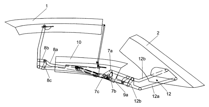
is The first exemplary embodiment of a folding top of the invention according
to
figures 1 to 17 comprises a first, front roof part 1, a second, rear roof part
2 and
a central roof part 10 which, in the closed state, is arranged between the
first
and the second roof parts 1, 2. The central roof part 10 is fixed to a central
link
10a, with the result that the central roof part 10 and the central link 10a
may be
2o regarded as a structural unit.
The first roof part 1 is connected to the central roof part 10 via a front
four-bar
mechanism 11, a front link 11 b of the front four-bar mechanism being
connected in an articulated manner to the central link 10a, and an outside
link
2s 11 a of the front four-bar mechanism 11 being articulated on the central
roof
part 10 from the outside. In the closed state according to figures 1, 2 and
11,
the outside link is arranged adjacent the outside of the central roof part 10,
the
outside link being located in a roof-rail or rain-channel recess of the
central roof
part 10.
The second, rear roof part 2 is articulated on the central link 10a by means
of a
rear four-bar mechanism 12. The rear roof part 2 comprises C-pillars of the
CA 02482319 2004-10-12
11
folding top and a solid rear window. The rear four-bar mechanism 12 comprises
a first rear link 12a and a second rear link 12b.
Overall, the first roof part 1 and the second roof part 2 can thus be pivoted
over
s the central roof part 10 in each case, it being possible for the rear roof
part 2
additionally to be pivoted over the front roof part 1.
The front four-bar mechanism 11 and the rear four-bar mechanism 12 are
connected to one another via a drivable positive control means 4, with the
result
to that a position of the first roof part 1 is clearly associated in each
case, in
mechanical terms, with a position of the second roof part 2.
The positive control means 4 comprises a first linkage 8, which activates the
front four-bar mechanism 11, a second linkage 9, which activates the rear four-
is bar mechanism 12, and a rotary link 7. The rotary link is connected to the
central link 10a such that it can be rotated at a first articulation 7a. The
rotary
link 7, in addition, can be rotated for driving action by means of a force-
introduction unit 5, which is designed as a linear hydraulic cylinder and is
supported against the central link 10a. In this case, the rotary link is
designed
2o as three-arm link. However, it is also possible, in particular, for a
rotary link to
be understood, in the sense of the invention, as a rotary plate or control
plate.
In particular a universally usable perforated plate can also be utilized as a
control plate, with the result that, by virtue of articulations being fitted
in a
variable manner on the perforated plate, it is possible, using standard
2s components, to provide a deceleration-control means which can be adapted to
different folding tops.
The first linkage 8 comprises a first, front control link 8a and two front
links 8b,
8c, it being possible to achieve a particularly large pivoting angle for the
front
3o four-bar mechanism 11 by virtue of the front link 11 b being connected to
the
first control link 8a by means of the two front links 8b, 8c. The first
control link
8a is connected to the rotary link 7 at a second articulation 7b of the rotary
link
7.
CA 02482319 2004-10-12
12
The second linkage 9 comprises a second, rear control link 9a, which is guided
in relation to the central link 10a via a small supporting link 9b. The second
control link 9a is articulated on an extension of the second rear link 12b,
with
s the result that the rear four-bar mechanism 12 is articulated on the second
control link 9a and can be activated via the latter.
The central roof part 10 or the central link 10a is connected to a bodywork-
mounted main-bearing unit 14 via a main four-bar mechanism 13, the main
io four-bar mechanism 13 comprising a first main link 13a and a second main
link
13b.
A rear stowage region 16 of the vehicle can be covered over by means of a rear
element 15, it being possible for the rear element 15 to be pivoted open
counter
is to the direction of travel in order to release a through-passage space for
the
folding top which is to be stowed.
As a particularly advantageous detailed solution for the folding top according
to
the invention which is illustrated in detail, in particular, in figures 15 to
17, the
20 outside link 11 a is not articulated on the central roof part 10 via a
conventional
rotary articulation. Rather, the articulation arrangement comprises a small
four-
bar mechanism 20, the central roof part 10 forming the base of the small four-
bar mechanism 20 and the outside link 11 a forming the connecting rod of the
small four-bar mechanism 20. A first link 20a and a second link 20b of the
small
2s four-bar mechanism 20 cross over one another. A short covering plate 21 can
be pivoted along essentially parallel to the links 20a, 20b of the small four-
bar
mechanism 20 about a dedicated articulation arrangement 21 a, the covering
plate 21 being guided with sliding action in the region of its end located
opposite its articulation arrangement 21 a.
In the case of a link being configured as an outside link, account should be
taken of a series of special features. As is also the case in the exemplary
embodiment shown, an outside link 11 a is advantageously arranged in a roof-
CA 02482319 2004-10-12
13
rail recess 10b, which is provided in any case in most modern folding vehicle
tops. The roof-rail recess 10b is laminated with a roof-rail covering 10c
outside
the region of the link 10a. The outside link 11 a expediently comprises a
corresponding lamination 22 positioned on the actual link, with the result
that,
s when the folding top is closed, the link is able to give the appearance of a
continuous drip molding 10c, 22. Such an arrangement, however, is
accompanied by the problem that, on account of being accommodated in a
sunken manner in the roof-rail recess 10b, the link 11 a would strike against
the
roof-rail covering 10c during a pivoting movement, at least when a large
to pivoting angle of the link 11 a is necessary. As a result of the
advantageous
detailed solution for the articulation arrangement of the link in the small
four-bar
mechanism 20, however, the link 11 a, together with its roof-rail cover 22,
passes out of the roof-rail recess 10b over its entire length even as it
begins to
pivot, with the result that a particularly large pivoting angle is made
possible.
is Figures 15 to 17 show that a free pivoting angle of the outside link of
more or
less 180 degrees is thus made possible.
The short covering plate 21, which can be pivoted along with the four-bar
mechanism 20, merely serves for covering over the roof-rail region above the
2o small four-bar mechanism 20 when the folding top is closed.
It should be mentioned that the prior art has disclosed solutions in which a
recessed, outside link can be covered by means of a strip-like flap which is
fitted in a pivotable manner on a roof part and forms a roof-rail cover. In
2s contrast, the solution described has considerable advantages since, for
example, the roof-rail cover can be secured directly on the link.
The invention functions, then, as follows:
3o Starting from the closed state of the folding top according to figures 1, 2
and 11,
in the first instance, a first part of a folding-top opening movement is
initiated.
The force-introduction unit 5 is actuated for this purpose, as a result of
which
the rotary link 7 is rotated, according to the illustrations, in the
counterclockwise
CA 02482319 2004-10-12
14
direction. A comparison of figures 1 to 10 clearly shows that, in the first
instance
here, it is predominantly the first linkage 8 which is actuated by the rotary
link,
whereas, on account of the position of the third articulation 7c in relation
to the
second linkage 9, the second linkage 9 is barely actuated in the first
instance, in
s particular in the relevant longitudinal direction of the second, rear
control link
9a.
In the first instance, it is thus predominantly the case that the front roof
part 1
pivots over the central roof part 10. The pivoting of the front roof part 1
prevails
to in the movement sequence approximately up to the position which is
illustrated
in figures 5 and 6.
The relative movement of the front roof part 1, which has already been pivoted
to a significant extent over the central roof part 10, subsequently slows
down.
is At the same time, the movement of the rear roof part 2 increases since (for
example from the position which is shown in figures 5 and 6) a very direct
conversion of the rotary movement of the rotary link 7 into a longitudinally
directed movement of the rear control link 9a then takes place. The
abovedescribed movement sequence of the two roof parts may thus be referred
2o to as quasi-sequential.
The first part of the folding-top opening movement is at an end when the three
roof parts 1, 2 and 10 are arranged entirely in the form of a stack (see
figures 9,
and 12).
2s
A second part of the folding-top opening movement is illustrated in the
overall
views of the folding top according to figures 12 to 14. In this case, pivoting
of
the main four-bar mechanism 13 driven by a second drive device displaces the
previously formed stack of roof parts 1, 2, 10 into a rear stowage region 16
of
3o the vehicle. For this purpose, the rear element 15 is first of all pivoted
open
counter to the direction of travel and then pivoted closed again.
CA 02482319 2004-10-12
A second exemplary embodiment of a folding top according to the invention is
described hereinbelow:
The second exemplary embodiment of the folding tap according to the invention
s comprises a first, front roof part 101 and a second, rear roof part 102. The
second roof part 102 rests on a rear element 115 with sealing action from
above when the folding top is closed, according to figure 18, and comprises a
rear window and pillars of the folding-top located alongside the rear window.
The rear element 115 comprises a front region 115a, as seen in the direction
of
to travel, which is arranged within the passenger compartment, and thus
beneath
the second roof part 102, when the folding top is closed. The region 115a
essentially corresponds to a rear-window shelf, arranged beneath a rear
window, in a conventional sedan with a solid roof.
is The first, front roof part is connected in a releasable manner to a
windshield
frame 130 of the vehicle when the folding top is closed.
A main-link mechanism 113 is mounted on the bodywork of the vehicle by
means of a main-bearing unit 114. This makes it possible, in particular, to
2o construct the folding top as a module which can be prefabricated
separately,
since the main-bearing unit essentially constitutes the only connection
between
the movable roof parts and the rest of the vehicle which is to be fitted.
The main-link mechanism is designed as a four-bar mechanism, the main-
2s bearing unit 114 or the bodywork of the vehicle forming the base of the
four-bar
mechanism. A first main link 113a and a second main link 113b form the links
of the main-link mechanism or four-bar mechanism 113. A carrying link 110a
forms the connecting rod of the main-link mechanism 113. The carrying link
11 Oa extends both to the front and rear over the distance which is necessary
for
3o coupling the four-bar mechanism 113, and serves as a carrier for the roof
parts
101 and 102. The carrying link 110a thus essentially corresponds to the
central
link 10a of the first exemplary embodiment. It can be seen from this that it
is
CA 02482319 2004-10-12
16
also possible for a central roof part to be additionally mounted on the
carrying
link 110a.
The first roof part 101 is mounted on the carrying link 110a in its front
region by
s means of a first link mechanism 111, the first link mechanism being designed
here as a four-bar mechanism and comprising a first front link 111 a and a
second front link 111 b. The first roof part 101 or a link which is fixed to
the first
roof part 101 forms the connecting rod of the first link mechanism 111.
to The second roof part 102 is mounted on the carrying fink 110a in its rear
region
by means of a second link mechanism 112, the second link mechanism 112
being designed here as a four-bar mechanism and comprising a first rear link
112a and a second rear link 112b. The second roof part 102 or a link which is
fixed to the second roof part 102 forms the connecting rod of the second link
Is mechanism 112.
A control link 104 is articulated in each case on the first front link 111 a
and the
second rear link 112b. This produces a positive control means 104 which
connects the first link mechanism 111 and the second link mechanism 112 to
20 one another in a positively controlled manner. A positively controlled link
chain
is thus formed overall, this chain comprising the first and the second front
links
111 a, 111 b, the first roof part 101, the first and the second rear links
112a,
112b, the second roof part 102, the carrying link 110a and the positive
control
means 104. As an alternative to the positive control means 104 being designed
2s as a straightforward control link 104, it is also possible to provide a
more
complex mechanism according to the first exemplary embodiment as the
positive control means, for example the positive control means 4, which is
shown in the first exemplary embodiment, with the integrated control device 6
for delaying the movement of the roof parts 101, 102, relative to one another.
A drive arrangement (not illustrated) for moving the roof parts 101, 102
relative
to one another can easily be provided as a linear force-introduction unit
which is
CA 02482319 2004-10-12
17
supported against two suitable links of the previously described positively
controlled link chain.
In the present exemplary embodiment, the rear element is designed in two
s parts, an articulation being provided between the rear-window-shelf region
115a
and the rest of the rear element 115. A particularly large trunk lid which can
be
pivoted open in the direction of travel is thus formed, as can be seen from
figure 27 in particular. This practice of dividing up the rear element in the
region
of the rear-window shelf, however, does not in any way correspond with the
io separately pivotable rear-window shelf which is known from the prior art
for the
purpose of releasing a space for the movement of the folding top. In the
closed
folding-top arrangement according to figures 18 and 27, the rear-window-shelf
region 115a cannot be pivoted.
is The invention functions, then, as follows:
Starting from the closed folding-top position according to figure 18, in the
first
instance, a first stage of movement of the roof opening is initiated by means
of
a first force-introduction unit (not illustrated), the main-link mechanism 113
zo staying in the same position. It can be seen from figures 19 to 21 that the
second roof part 102 is pivoted in the direction of travel in the first
instance by
the driven movement of the previously described positively controlled link
chain,
the second roof part raising up from the rear element and being moved away
upward, and in the direction of travel, from the rear element.
At the same time, the first roof part 101 is pivoted rearward, counter to the
direction of travel, away from the windshield frame, with the result that the
roof
parts 101, 102 move toward one another, in which case they essentially
maintain their spatial orientation. The first, front roof part 101 here is
pivoted
over the second, rear roof part 102 until a stacked position of the roof parts
according to figure 21 has been reached. The stack of roof parts is connected
to the vehicle via the main-link mechanism 113.
CA 02482319 2004-10-12
18
The rear element 115 is then pivoted open counter to the direction of travel
(see figure 22), in which case in particular the region 115a of the rear
element
115 is pivoted along integrally. This is made possible by the previously
s described movement of the second roof part 102, as a result of which the
movement space for the rear element 115 has been released.
Once a rear stowage region 116 for the folding top has thus been released, the
main-link mechanism 113 is moved by means of a second drive device (not
io illustrated). According to the movement steps shown in figures 23 to 25,
the
stack of roof parts here is displaced over an arcuate path of motion into the
rear
stowage region 116.
The rear element 115 is then closed again (see figure 26), in which case it
is covers over the stowed roof. In particular, the front region 115a of the
rear
element 115 adjoins a rear seat back 131, as is also the case when the folding
top is closed.
It can be seen from the open state of the folding top according to figure 26
that
2o a useful trunk volume remains beneath the lowermost, second roof part 102.
For the closing operation of the folding top, the previously described
kinematics
take place in reverse order.