Note: Descriptions are shown in the official language in which they were submitted.
. . .
CA 02483117 2013-07-11
Multi-SymbM Encapsulated OFDM System
CROSS-REFERENCE TO RELATED APPLICATIONS
FIELD OF THE INVENTION
[1] The present invention relates to communication systems using OFDM
transmission
format, and more specifically to formatting an OFDM signal for improving
system
performance in the presence of linear channel distortion.
BACKGROUND OF THE INVENTION
[2] Orthogonal frequency division multiplexing (OFDM) has received
considerable attention
for its robustness against inter-symbol interference (1ST) and impulse noise,
low
implementation complexity and high spectral efficiency. It was first
standardized for Digital
Audio and Video Broadcasting applications, and later for digital subscriber
loops (DSL) and
wireless LAN. One important advantage of an OFDM system is its simple receiver
structure
utilizing a frequency domain equalizer with only one complex multiplication
per sub-carrier.
This is achieved by inserting a time domain cyclic prefix (CP) in front of
each OFDM
symbol, enabling the receiver to separate a steady-state response from a
transient response of
the communications channel. The CP, which is a cyclic extension of the inverse
discrete
Fourier transformation (IDET) output, has to be at least as long as the
channel impulse
response (CIR) in order to avoid inter-symbol interference. Therefore,
redundancy is
unavoidably introduced into conventional OFDM systems. This restricts
achievable
bandwidth efficiency, especially for channels with a very long CIR.
[3] To mitigate this problem, many OFDM receivers apply a finite-impulse
response (FIR)
time domain equalizer (TEQ) before the discrete Fourier transform (DFT) in
order to shorten
the effective length of the CIR. However, this significantly undermines the
major advantage
of OFDM, i.e., the simple frequency domain equalization.
[4] Further, conventional OFDM transmission is known to be sensitive to
synchronization
errors, represented by frequency and timing offsets. Frequency offset at the
receiver
1
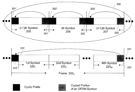
CA 02483117 2004-09-29
introduces inter-carrier interference (ICI) due to the loss of orthogonality
among
demodulated sub-carriers. Timing offset results in a rotation of the OFDM sub-
carrier
constellation. As a result, an OFDM system cannot recover the transmitted
signal without a
near perfect synchronization, especially when a high-order quadrature
amplitude modulation
(QAM) of the subcarriers is used.
[5] Another disadvantage of the conventional OFDM transmission is its high
peak-to-average
power ratio (PAPR). As a result, OFDM signals cover a wide range of amplitudes
but dwell
mostly at small values. The disadvantages caused by this are twofold. As only
the linear
region of the amplifier can be used, high PAPR means low efficiency of the
amplifier. On the
other hand, OFDM signals have to be normalized to the conversion range of
digital-to-analog
(D/A) and analog-to-digital (A/D) converters for transmission and signal
processing
purposes. For a given quantization word length, a higher PAPR implies a lower
signal-to-
quantization-noise ratio.
[6] The instant invention provides a new and simple multi-symbol encapsulated
(MSE)
OFDM system which employs a different type of cyclic prefix; instead of using
one cyclic
prefix for each OFDM symbol, a number of OFDM symbols are grouped together as
a frame
and protected by one single cyclic prefix. Two different frame implementations
can be
realized for different purposes, i.e., either to improve the bandwidth
efficiency or to improve
the robustness to synchronization errors and to reduce the PAPR of the MSE-
OFDM system,
as illustrated in Figure 2 and 8. These two different systems are named CP-
reduced and FFT
size-reduced MSE-OFDM system, respectively.
[7] H. Sari, et al. in an article "Transmission Techniques for Digital
Terrestrial TV
Broadcasting," IEEE Commun. Mag., vol. 33, no. 2, Feb. 1995, pp. 100-109, and
D. Falconer
et al. in an article "Frequency domain equalization for single-carrier
broadband wireless
systems", IEEE Communications Magazine, Volume: 40, Issue: 4, April 2002
Pages: 58
66, disclosed grouping multiple single carrier symbols into a frame followed
by a cyclic
prefix to facilitate frequency-domain equalization in single carrier systems.
This approach
essentially emulates the time-domain signal structure of the conventional OFDM
system by
providing a cyclic data frame at least several times longer than the channel
response time;
2
=4...,0%,..g*Mett-****.=
______________________________________________________________________ =
CA 02483117 2004-09-29
using a cyclic prefix in a single-carrier system for each symbol would be
impossible because
of a very short duration of the single-carrier symbol in a system having a
comparable bit rate.
[8] Encapsulating multiple OFDM symbols with a single cyclic prefix in one
OFDM frame
has not been disclosed heretofore; conventional OFDM systems already provide a
cyclic
frame structure enabling frequency-domain equalization. However, the multi-
symbol
encapsulation of OFDM symbols in a cyclic OFDM frame with a single cyclic
guard portion
would provide additional benefits compared to prior-art OFDM systems and the
system of
H. Sari et al., by potentially improving the bandwidth efficiency, enhancing
system's
robustness to synchronization errors and suppressing digitization noise
through PAPR
reduction.
[9] It is therefore an object of this invention to provide a method for OFDM
transmission
wherein a high bandwidth efficiency is achieved by encapsulating multiple OFDM
symbols
in a frame with a single cyclical prefix.
[10] It is another object of this invention to provide a method of a multi-
symbol
encapsulated (MSE) OFDM transmission with low peak-to average power ratio and
enhanced tolerance to frequency synchronization errors.
[11] It is another object of this invention to provide an MSE-OFDM system
having high
bandwidth efficiency.
[12] It is another object of this invention to provide an MSE system for OFDM
transmission having low peak-to average power ratio and enhanced tolerance to
frequency
synchronization errors.
SUMMARY OF THE INVENTION
[13] In accordance with the invention, a communication system for transmitting
information in an OFDM format is provided, comprising at least one of (a) an
OFDM
transmitter for transmitting a multi-symbol encapsulated OFDM signal along a
transmission
channel, and (b) an OFDM receiver for receiving the multi-symbol encapsulated
OFDM
signal from a transmission channel, wherein the multi-symbol encapsulated OFDM
signal
comprises a sequence of OFDM frames bearing the information, each said frame
including a
sequential plurality of OFDM symbols and only one cyclic guard portion, said
cyclic guard
portion appended at one end of the frame and replicating an opposing end of
the frame, and
3
CA 02483117 2004-09-29
wherein the multi-symbol encapsulated OFDM signal has at least two OFDM
symbols
between each two consecutive guard portions.
[14] In accordance with one embodiment of the invention, the communication
system
comprises the OFDM transmitter for transmitting a multi-symbol encapsulated
OFDM
signal, said transmitter including: a multi-symbol encapsulator for converting
an input
sequence of m-ary data symbols into a sequence of the OFDM frames, a D/A
converter for
converting the sequence of OFDM frames into an OFDM signal waveform, and an RF
transmitter for transmitting the OFDM signal waveform along a transmission
channel.
[15] In accordance with another embodiment of the invention, the communication
system
includes the OFDM receiver for receiving the multi-symbol encapsulated OFDM
signal
transmitted along the transmission channel, said OFDM signal further
comprising a preamble
sequence having a pre-determined structure, wherein the OFDM receiver
comprises: (a) an
A/D converter for sampling the received OFDM signal at a sampling frequency
and for
producing a sequence of received waveform samples; (b) a synchronization and
channel
estimation unit adapted to identify the preamble sequence in the sequence of
received
waveform samples and to perform channel and frequency offset estimation from
the
received preamble sequence and the pre-determined structure of the preamble
sequence; (c) a
cyclic guard removing unit adapted to identify information-bearing OFDM frames
in the
sequence of received waveform samples, to remove the cyclic guard portions
from each
identified OFDM frame and to produce a sequence of guard-removed OFDM frames;
(d) a
channel equalizer, comprising: a first processing unit adapted to perform an
MxN points
DFT and M x N complex multiplications for converting the guard-removed OFDM
frames
to frequency domain, and for frequency-domain equalization to produce a
sequence of=
equalized frame spectra, and a second processing unit adapted to perform an M
x N point
inverse DFT on each equalized frame spectrum to produce a sequence of
equalized guard-
less OFDM frames, each comprising M OFDM symbols; (e) a third processing unit
adapted
for splitting the equalized frame into MOFDM symbols, performing MN-point
inverse DFTs
for demodulating the equalized guard-less OFDM frames and for producing a set
ofMxN
received m-ary symbols from each equalized OFDM frame; and (f) a parallel-to-
serial
converter adapted to convert the set of Mx N received m-ary symbols into a
received
sequence of m-ary data symbols.
4
CA 02483117 2004-09-29
[16] In accordance with another aspect of this invention, a method for an OFDM
transmission is provided comprising the step of forming an OFDM signal
comprising a
sequence of OFDM symbols and a sequence of cyclic guard portions, the OFDM
signal
having at least two OFDM symbols between each two consecutive cyclic guard
portions,
wherein the cyclic guard portions replicate end portions of OFDM symbols.
[17] In one embodiment of this aspect of the invention, the step of forming a
sequence of
multi-symbol OFDM frames by performing the steps of: (a) providing an input
sequence of
m-ary data symbols; (b) dividing the input sequence of m-ary data symbols into
subsets of N
m-ary data symbols, wherein N> 1; (c) performing frequency domain multiplexing
of each
subset of N m-ary data symbols by modulating N frequency subcarriers therewith
and using
an N-point inverse DFT for producing N waveform samples forming an N-point
OFDM
symbol; (d) grouping the N-point OFDM symbols into ordered sets of M OFDM
symbols,
the ordered sets forming data sections of the frame, wherein M> 1; (e) forming
a multi-
symbol OFDM frame from each ordered set of M OFDM symbols by appending a
cyclic
guard portion at an end of the data section of the frame, the cyclic guard
portion replicating
an opposing end portion of the frame and having P wavefoiin samples.
[18] One embodiment of the method of present invention provides OFDM frames
having a
length exceeding the length of the channel impulse response by at least a
factor of 30 for
providing high bandwidth efficiency.
[19] Another embodiment of the method of present invention provides OFDM
frames
having a length exceeding the channel impulse response length by at most a
factor of 16, and
comprising each at least 4 OFDM symbols for providing at least one of: reduced
frequency
offset sensitivity of the OFDM system, and reduced PAPR.
BRIEF DESCRIPTION OF THE DRAWINGS
[20] Exemplary embodiments of the invention will now be described in
conjunction with
the drawings in which:
[21] FIG. lA is a block diagram of a prior-art OFDM transmitter.
CA 02483117 2004-09-29
[22] FIG. 1B is a block diagram of a prior-art OFDM receiver.
[23] FIG. 2A is a diagram of an MSE-OFDM frame for a CP-reduced transmission
system
in comparison with a conventional OFDM signal structure;
[24] FIG. 2B is a diagram of an MSE-OFDM frame sequence wherein cyclic guard
portions replicate frame portions which are not part of a data section of the
frame.
[25] FIG. 2C is a diagram of an MSE-OFDM frame sequence having identical
cyclic
guard portions.
[26] FIG. 3 is a block diagram of an OFDM transmitter with a parallel
encapsulator
according to instant invention.
[27] FIG. 4 is a block diagram of a serial multi-symbol encapsulator.
[28] FIG. 5 is a block diagram of a serial multi-symbol encapsulator with a
reduced buffer
size.
[29] FIG. 6 is a block diagram of an OFDM receiver according to instant
invention.
[30] FIG.7 is diagram of an MSE-OFDM signal including a preamble.
[31] FIG. 8 is a diagram of an MSE-OFDM frame for an FFT-size reduced
transmission
system in comparison with a conventional OFDM signal structure.
DETAILED DESCRIPTION OF THE PREFERRED EMBODIMENTS
[32] Before providing a detailed description of exemplary embodiments of an
OFDM
transmission system and method of the present invention, general principles of
OFDM
transmission will be briefly discussed with reference to FIG. 1A and B,
showing a prior-art
OFDM transmitter and receiver respectively. A detailed description of a
typical prior-art
OFDM system can be found for example in US Patent 5,732,113 issued to Schmidl
et al,
which is incorporated herein by reference.
6
CA 02483117 2004-09-29
[33] An OFDM transmitter 5 receives an input binary information sequence 12.
The
binary sequence 12 is fed into an encoder 10, which converts it into an input
sequence of m-
ary data symbols X(k). A sequence of N m-ary data symbols X(k) is then passed
onto an
OFDM symbol generator 35, typically comprising a serial-to parallel converter
20, a digital
signal processor (DSP) 30, and a parallel-to-serial converter and CP adder 40.
The digital
signal processor (DSP) 30 is programmed to perform an inverse discrete Fourier
transform
(IDFT) or, preferably, an inverse fast Fourier transform (IFFT) on the input
sequence of N
complex m-ary data symbols.
[34] Encoder 10 typically performs an m-ary quadrature amplitude modulation
(MQAM)
encoding of consecutive sub-segments of v input bits, m=2', mapping thereby
segments of
v bits to predetermined corresponding complex-valued points in an m-ary
constellation. Each
complex-valued point in the constellation represents discrete values of phase
and amplitude.
The sequence of N m-ary data symbols is used then by the IFFT processor 30 as
frequency-
domain complex modulation coefficients for modulating N frequency-domain sub-
carriers,
thereby forming an N-point OFDM symbol defined as
1 N-1 nk
[35](x(n) = E X k)e n=0, I, 2, ......, N-1.
(1)
k=0
[36] Encoder 10 may also use a block and/or convolutional coding scheme to
introduce
error-correcting and/or error-detecting redundancy into each segment of v x N
bits and then
sub-divide the coded bits into N sub-segments of v bits. The integer v
typically ranges from
2 to 6.
[37] The OFDM symbol defined by the equation (1) is then passed onto the
parallel-to-
serial converter 40 which converts the OFDM symbol into a time domain, where
it is
represented by a sequence of N digital samples spaced by time intervals
ts=T/N, where T is
a duration of one time-domain OFDM symbol, which corresponds to frequency
spacing
between subcarriersf I/T.
[38] As a result of the discrete-valued modulation of the OFDM sub-carriers in
frequency
domain by the m-ary data symbols over OFDM symbol intervals of T seconds, the
OFDM
7
CA 02483117 2004-09-29
sub-carriers each display a sinc(x) = sin(x)/x spectrum in the frequency
domain. By spacing
each of the sub-carriers 1/T Hz apart in the frequency domain, the primary
peak of each sub-
carrier's sinc(x) spectrum coincides with a null of the spectrum of every
other sub-carrier. In
this way, although the spectra of the sub-carriers overlap, they remain
orthogonal to one
another.
[39] The parallel-to-serial (P/S) converter 40 performs also another important
function ¨ it
extends the time-domain OFDM symbol by appending a cyclic prefix (CP) at the
beginning
of each OFDM symbol to protect it from channel-induced inter-symbol
interference (ISO. 1ST
typically appears due to multi-path interference of the OFDM signal during
channel
propagation causing a channel delay spread. Duration of the CP exceeds the
delay spread t to
protect the symbol from the 1ST. The CP is typically a copy of an end portion
of the symbol
appended at the beginning of the symbol. Alternatively, the CP can be a copy
of a portion of
the beginning of the symbol appended to an opposing end of the symbol. The CP
will be also
referred to hereafter in this specification as a cyclical guard portion.
[40] In prior-art systems, the CP is appended in front of each OFDM symbol to
protect
each symbol from ISI, and its length P, i.e. a number of waveform samples
therein, is
selected so that P exceeds a channel impulse response length L = r /ts. The
delay spread T
can be determined by estimating a decay time of the channel impulse response
h(t) at the
receiver. Obviously, adding the CP to each symbol decreased bandwidth
efficiency of the
OFDM transmission by a factor z = N/(P+N).
[41] The cyclically extended digital time-domain OFDM symbols are then passed
to a
digital-to-analog converter 50 to produce an analog OFDM signal which is then
fed into an
RF transmitter 55. Many variations of the RF transmitter 55 exist and are well
known in the
art, but typically, the RF transmitter 55 includes a low-pass filter 60, an RF
modulator 70
typically comprising an RF local oscillator wherein the signal is frequency up-
converted to
an RF central frequency, a power amplifier 80 and an antenna 90. Typical
embodiments of
modules 50, 60, and 70 can be found in US Patent 5,732,113.
[42] In order to receive the OFDM signal and to recover the input data bits
that have been
encoded into the OFDM sub-carriers at a remote location, an OFDM receiver must
perform
8
CA 02483117 2004-09-29
essentially the inverse of all the operations performed by the OFDM
transmitter described
above. These operations can be described with reference to FIG. 1B, which is a
block
diagram of a typical OFDM receiver according to the prior art.
[43] Through antenna 15, a received OFDM signal is fed into an analog-to-
digital
converter 25 where it is down-converted in frequency to remove the RF carrier
from the
signal and digitized at a sampling rate'', to produce discrete-time waveform
samples of the
received OFDM signal. The difference between the downshifting frequency f: of
the
receiver and the carrier frequency fe of the transmitter is the frequency
offset, Af = fe' ,
which should be equal to zero in an ideal receiver; nonzero frequency offset
can lead to inter-
carrier interference (ICI) and transmission errors.
[44] The output of the AID converter 25 is then delivered to DSP 35 as a
complex-valued
OFDM signal r(n), where index n represents digitized time samples. DSP 35
identifies
OFDM symbol boundaries in the received sequence of waveform samples r(n) ,
splits it into
cyclic-extended OFDM symbols, removes the cyclic prefixes from each such
symbol, and
performs serial-to-parallel 1 to N conversion of the received and digitized
OFDM signal,
producing a parallel stream of N complex waveform samples. The DSP 35 can also
perform
additional operations on the samples of the received OFDM signal, which may
include for
example synchronizing D/A converter to the timing of the symbols and data
samples within
the received OFDM signal, and estimating and correcting for the carrier
frequency offset of
the received OFDM signal. The parallel sets of N complex waveform samples are
then
passed onto a DSP 45 programmed to perform an N- point DFT, typically ¨ FFT,
perfoilhing
simultaneously frequency-domain equalization, typically done by multiplying
the computed
Fourier coefficients R(k) for each k-th sub-carrier, k = 0,...N-1, by an
inverse of an estimated
channel transfer function H(k) at a corresponding sub-carrier frequency.
[45] DSP 45 thus computes a sequence of equalized frequency-domain MQAM
symbols,
REQw(k), from each symbol of the OFDM signal by demodulating the sub-carriers
of the
OFDM signal by means of the FFT calculation. DSP 45 then delivers these sets
of MQAM
symbols to a parallel-to-serial converter 55 producing a sequence of the MQAM
symbols,
which is finally passed to a MQAM decoder 65 which outputs an output binary
sequence
9
=
CA 02483117 2004-09-29
reproducing the input binary sequence. This recovery is performed by decoding
the
frequency-domain MQAM symbols to obtain a stream of data bits 104 which should
ideally
match the stream of data bits 12 that were fed into the OFDM transmitter 5.
This decoding
process can include soft Viterbi decoding and/or Reed-Solomon decoding, for
example, to
recover the data from the block and/or convolutionally encoded m-ary data
symbols.
[46] A typical feature of the aforedescribed prior-art OFDM transmission
system is the use
of a cyclic prefix (CP) which is appended at the beginning of each OFDM symbol
to combat
ISI. This CP should be at least as long as the length of the channel ClR to
shield the OFDM
symbols from the channel-induced ISI; however, having the CP attached to each
symbol
decreases a bandwidth efficiency of the OFDM transmission by a factor of z =
N/(P+N). For
channels with a long impulse response, this penalty in bandwidth efficiency
can be
significant, as the length of one OFDM symbol is typically limited by carrier
spacing and
peak to average power ratio (PAPR), as the carrier spacing cannot be too small
and PAPR
cannot be too large.
[47] Exemplary embodiments of a communication system and method for
transmitting
information in OFDM format will now be discussed with reference to FIGs. 2-7.
[48] A principal feature of the OFDM transmission system of present invention
is the use
of multi-symbol encapsulation, wherein multiple OFDM symbols are grouped
together in a
frame which includes a single cyclic prefix, or more generally ¨ a single
cyclic guard portion
having a length that preferably exceeds the CIR length. This cyclic guard
portion can be
attached either at the beginning of the frame before the first OFDM symbol of
the frame
forming thereby the cyclic prefix, or after the frame following the last OFDM
symbol of the
frame forming a cyclic suffix (CS).
[49] Hereinafter in this specification, we will be referring to the OFDM frame
as having
two opposing ends rather than a beginning and an end; this is illustrated in
FIG.2A wherein
the frame 250a has two opposing ends 221 and 222, and two corresponding
opposing end
portions 223 and 223'. This terminology allows expressing more clearly
similarity between
frames having a CP and a CS, and is equally applicable to a frame converted in
a parallel
format, which will be discussed hereafter in this specification.
CA 02483117 2004-09-29
[50] If the C1R length L, which is in the context of this specification
defined in relative
terms as L = MIT < P, where t is a characteristic decay time of the CIR, T is
a duration of
one OFDM sample and N is the size of the DFT used to form the OFDM symbol, the
effect
of the channel on the OFDM signal will be very similar to an effect of the
channel on an
OFDM signal wherein the OFDM symbol is periodically repeated that can be
described by a
cyclic convolution. This allows the use of FFT-assisted frequency-domain
equalization to
remove linear channel-induced distortions such as 1ST from the received
signal, as the FFT is
equivalent to an inverse of cyclic convolution. Making the signal appear
periodic by inserting
a cyclic guard portion at one of two ends of a frame is therefore essential
for proper use of
FFT for frequency-domain equalization; in that instance, the effect of 1ST, or
any linear
channel distortion, can be removed from the received signal by FFT-assisted
frequency-
domain equalization without attaching a cyclic prefix to each symbol. This
frequency-domain
equalization however needs to be performed on a whole frame rather than on
each symbol,
increasing therefore the required FFT size. This should not pose a significant
problem for
many applications due to commercial availability of fast DSP processors
capable of
performing FFT operations on large number of samples.
[51] In the following description, Nand M denote the size of the inverse DFT
modulator,
preferably embodied as an IFFT modulator, and the total number of OFDM symbols
in one
MSE-OFDM frame, respectively. The length of the cyclic guard portion is P
samples. To
illustrate the use of the cyclic guard portion in the MSE-OFDM signal
structure of the instant
invention, the time-domain frame structures of a conventional OFDM system and
of one
embodiment of the MSE-OFDM system are shown in FIG. 2A. As explained earlier
in the
specification, in the MSE-OFDM system of the present invetion only one cyclic
prefix 223'
is used for a group of consecutive time-domain OFDM symbols 2201, 2202¨ 220m ,
which
form a data section of the frame. In this embodiment, the cyclic prefix 223'
is the cyclic
extension of the last OFDM symbol 220m in the same frame, i.e. a copy of its
end portion
223 appended to the opposing end 222 of the frame. Alternatively, in another
embodiment
the first P samples of the OFDM symbol 2201 are copied and the copy appended
at the
opposing end 221 of the frame forming a cyclic suffix. In another embodiment
shown in
FIG.2B, the cyclic guard portions 224' is a copy, or a replica, of an opposing
end portion 224
11
CA 02483117 2004-09-29
of the frame 251, wherein the opposing end portion of the frame 224 is a sub-
sequence of
waveform samples which is not a part of any of the OFDM symbols 2201, ...220m
forming
the data section of the frame, but can be for example a training sequence.
[52] With reference to FIG.2C, in other embodiment the cyclic guard portion of
a frame is
a copy of an end portion of an adjacent frame; e.g. the cyclic guard portion
226a of a frame
253 is a copy of a cyclic guard portion 226b of the preceding frame 254, and
the cyclic guard
portion 226b replicates a cyclic guard portion 226c of its preceding frame. In
this
embodiment, all cyclic guard portions are substantially identical and can be
used as training
sequences.
[53] To support the novel MSE-OFDM frame structure shown in FIG.2,
modifications
have to be made to both the aforedescribed prior art OFDM transmitter and the
prior art
OFDM receiver shown in FIG.1A and 1B.
[54] FIG. 3 shows a block diagram of an exemplary embodiment of the MSE-OFDM
transmitter generating a CP-extended OFDM frame; with minimal modifications
that would
be obvious to those skilled in the art, the transmitter shown in FIG.2 can be
adopted to
generate a CS-extended frame.
[55] Each block in the diagram shown in FIG.3 is a functional unit of the OFDM
transmitter adopted to perform one or several steps of the method of OFDM
transmission of
the present invention in one embodiment thereof; these steps will be also
hereinafter
described in conjunction with the description of the corresponding functional
blocks of the
transmitter.
[56] Similar to the conventional OFDM transmitter of prior art shown in FIG.
1A, the
MSE-OFDM transmitter 300 has at its input the encoder 10 that converts the
input binary
sequence 12 into the input sequence of m-ary data symbols X(k), typically in
MQAM format,
which are used as complex modulation coefficients to modulate the frequency-
domain sub-
carriers of the OFDM signal in accordance with equation (1). However, M OFDM
symbols
have to be generated before the CF insertion at the transmitter side. The OFDM
symbol
generator 35 of the prior art transmitter is therefore replaced by a multi-
symbol encapsulator
12
CA 02483117 2012-10-24
Doc. No.: 102-4 CA Patent
335, which includes a 1 to (N x M) serial-to-parallel converter 320, MN-point
IFFT
modulators 3301, 3302- 330m which can be embodied as M DSP units programmed to
perform N-points FFT or, preferably, as a single DSP unit, and a serial-to-
parallel converter
340. A main function of the mutli-symbol encapsulator 335 is to receive the
input sequence
X(k) and to convert it into an output sequence of multi-symbol cyclically-
extended OFDM
frames 250. Accordingly, the S/P converter 320 converts the input stream of m-
ary symbols
X(k) into an (N x M) parallel stream, splits it into M N-point groups of the m-
ary data
symbols, and passes said groups onto M N-point IFFT modulators 3301, 3302-
330M, each of
which functions similarly to the IFFT modulator 30 of the prior art OFDM
transmitter 5 to
produce an N-point OFDM symbol. The IFFT modulators 3301, 3302- 330m together
produce a parallel stream of M groups of N complex time-domain modulation
coefficients
si(n), hereinafter also referred to as complex waveform samples, forming M
OFDM symbols,
which are then converted in a serial form by the P/S converter 340 to form a
time-domain M-
symbol OFDM frame.
[57] The P/S converter 340 also performs the function of adding a cyclic
prefix 223' to the
frame, by copying the end portion 223 of the frame and appending the copy at
the beginning
of the frame as explained above in this specification, to form a cyclical-
extended OFDM
frame, outputting a sequence of cyclic-extended OFDM frames 250.
[58] An /-th cyclic-extended MSE-OFDM frame is described by the equation (2)
N-1 M -1 N-1
[591s1 = X/M_l(k)YJI(n,k) +11X ,t(k) Vi2(n ¨ iN ¨ AP , k) (2)
k=O 1=0 k=0
[60] where the two subscripts ie [0,M ¨1] and / mean the i-th OFDM symbol of
the /-th
frame. VI (n, k) and V2 (n, k) are two rectangular signal multiplexing window
functions
corresponding to the cyclic prefix and the M information carrying OFDM symbols
defined as
follows
13
CA 02483117 2004-09-29
,
{ 1 j27rk(N-P+n)
____________________________ e N
, 0 __ri__P-1
[61] Vii(n,k) = Nr-A7 (3)
0, elsewhere
[62] and
{ _______________________________ 1 j2rdc(n-P-iN)
, _________________________________ e N , P ._.n MN +P-1
[63] v2(n¨iN¨P,k)= vN (4)
0, elsewhere
[64] The sequence of cyclically extended digital time-domain OFDM frames
described by
equation (2) forms an output of the P/S converter and CP adder 340, which is
passed onto the
D/A converter 350 to produce an analog OFDM signal bearing the sequence of the
OFDM
frames, which is then fed into an RF transmitter 355. In the exemplary
embodiment shown
in FIG. 3, the RF transmitter 355 includes an RF modulator 370 for frequency
up-conversion
of the analog waveform outputted from the D/A converter 350 into the RF
frequency range, a
power amplifier 380 for amplifying the up-converted OFDM signal, and an
antenna 390 for
transmitting the OFDM signal along a transmission channel. Many variations of
the RF
transmitter 355 are known and can be used in this embodiment, as would be
obvious to those
skilled in the art.
[65] The aforedescribed embodiment of the MSE-OFDM transmitter of present
invention
includes the multi-symbol encapsulator 335 performing parallel DFT processing
of NxM
complex symbols, wherein all M symbols of one OFDM frame are formed
simultaneously.
FIG.4 shows a block diagram of another embodiment of the multi-symbol
encapsulator 335,
labeled "335a", wherein the function of forming the OFDM frames is realized
using a single
N-point inverse DFT modulator 730, embodied as a DSP unit adapted to perform
an N-point
1FFT. The multi-symbol encapsulator 335a receives the input sequence of m-ary
symbols
X(n), preferably but not exclusively in MQAM format, and passes it to a serial-
to-parallel
converter 720, which converts the input sequence X(k) into a sequence of
parallel N-symbol
words formed by a sub-sequence of N consecutive m-ary symbols, and passes
these words to
the DSP unit 730, wherein the m-ary symbols from each word are used as
modulation
14
..._ _
CA .02483117 2012-10-24
Doc. No.: 102-4 CA Patent
coefficients to form an N-point OFDM symbol x(n) using the N-point IFFT; up to
this point,
the system is similar to a corresponding section of the prior art system shown
in FIG.1. Next,
the N complex waveform samples forming the OFDM symbol x(n) are delivered to a
memory buffer having a size sufficient to store at least MxN complex values,
which is
programmed to accumulate MxN complex waveform samples forming M consecutive
OFDM symbols; the parallel set of MxN complex waveform samples is then passed
to the
P/S converter and CP adder 340 where they are converted in a serial format to
form a time-
domain M-symbol OFDM frame, and the CP is added at the beginning of the frame
as
described heretofore in this specification with reference to FIG.3.
[66] Instead of adding a cyclic prefix at the beginning of the frame as was
mentioned before
in this specification, a cyclic guard portion of the same length P replicating
the first P
samples of the first OFDM symbol of the frame can be equally added at the end
of the frame,
forming a cyclic suffix (CS). Using the CS in the MSE-OFDMsystem can be
advantageous
as it allows reducing the size of the buffer used in the OFDM transmitter.
[67] FIG.5 shows a block diagram of another embodiment of the multi-symbol
encapsulator
in accordance with the instant invention. In this embodiment, the multi-symbol
encapsulator
335b adds a cyclic suffix at the end of the word, which allows decreasing the
memory size of
the used buffer to the length P of the cyclic suffix. The first two blocks 720
and 730 of the
multi-symbol encapsulator 335b are the same as in the previous embodiment
shown in FIG.4
and perform the same functions, outputting a sequence of parallel N-element
sets of complex
waveform samples each forming an OFDM symbol x(n). This output is sent to a
memory
buffer unit 735b capable of storing at least P complex waveform samples. The
memory
buffer unit 735b is programmed to count OFDM symbols produced by the N-point
IFFT
modulator 730, to store first P samples of every (1+jM) OFDM symbol in the
sequence of
OFDM symbols produced by the N-point IFFT modulator 730, where j = 0,1.....,
and to
deliver them to a P/S converter and cyclic suffix adder 740 once a ((j+1)M)th
OFDM symbol
arrives. The P/S converter and cyclic suffix adder 740 converts the sequence
of N-point sets
of complex waveform samples into a sequence of time-domain OFDM symbols.
Additionally, after outputting every Mth OFDM
CA 02483117 2004-09-29
symbol, it inserts in the output OFDM sequence the sequence of P samples
received from the
buffer 735b, thereby forming a cyclic suffix of an OFDM frame.
[68] An exemplary embodiment of an MSE-OFDM receiver according to the instant
invention is shown in FIG.4 and will now be described. For clarity, the MSE-
OFDM signal
embodiment with a cyclic prefix will be assumed. However, only small
modifications would
be required to the receiver of this embodiment if a cyclic-suffix extend frame
format is used
instead, and these modifications would be obvious to those skilled in the art.
[69] Each block in the diagram shown in FIG.4 is a functional unit of the
receiver adopted
to perform one or several steps of the method of OFDM transmission of the
present invention
in one embodiment thereof; these steps will be also hereinafter described in
conjunction with
the description of the corresponding functional blocks of the receiver.
[70] An RF antenna 415 receives the transmitted OFDM signal affected by the
transmission channel, and passes it to an A/D converter 425. The RF antenna
includes an RF
receiver which is not shown and which also performs a function of frequency
down-
conversion to reverse the frequency up-conversion performed by the RF
modulator 370. The
difference between the downshifting frequency L of the receiver and the
carrier frequency
fc of the transmitter is the frequency offset, Af = fe ¨ f; , which should be
equal to zero in
an ideal receiver; nonzero frequency offset can lead to inter-carrier
interference (ICI) and
transmission errors. Those skilled in the art would appreciate that different
versions of the RF
receiver exist that can be used in this embodiment.
[71] The AID converter 425 digitizes the received OFDM signal by sampling it
at the
sampling frequencyfs, to produce a sequence of received OFDM samples r(n),
where index n
marks individual OFDM samples in the time-ordered sequence r(n). As we
mentioned
before, the frequency offset here refers to carrier frequency offset, i.e.,
the difference
between the downshifting frequency and the carrier frequency of the
transmitter.
[72] The output of the AID converter 425 is then split into two data streams
426 and 427,
each carrying the sequence of the received complex-valued OFDM samples. Stream
426 of
the received OFDM samples is delivered to a cyclic guard removing unit 435,
which is
16
CA 02483117 2004-09-29
programmed to identify OFDM frame boundaries in the received sequence of OFDM
samples r(n) using a timing synchronization signal supplied by a
synchronization and channel
estimation unit 433, to remove the cyclic prefix from each frame, and to
perform serial-to-
parallel 1 to (N x M) conversion of the received and digitized OFDM signal,
producing a
parallel stream of (N x M) complex waveform samples. This parallel stream is
then passed to
a channel equalizer 436.
[73] The received OFDM samples are also fed into a synchronization and channel
estimation unit 433 embodied as a DSP and adapted to generate timing
information and to
perform channel and frequency offset estimation. The DSP 433 supplies timing
information
to the A/D converter 425 and the cyclic guard removal unit 435. It also
supplies an estimated
channel transfer fimction fl and an estimated frequency offset to the channel
equalizer 436.
[74] Channel equalization in the MSE-OFDM receiver is performed differently
from the
aforedescribed channel equalization in the prior art OFDM receiver; according
to the present
invention, the channel equalization is performed on a per-frame rather than
per-symbol basis,
and the channel equalization and OFDM de-modulation are perfoinied in two
different steps.
[75] For each identified OFDM frame, the cyclic guard removal unit 435
produces a
sequence of M x N received wavefoini samples forming a guard-removed OFDM
frame and
passes it to a channel equalizer 436 formed by a sequentially-connected first
and second
processing means 437, 439. Functioning of this channel equalizer will now be
explained.
[76] An OFDM frame sequence formed by the multi-symbol encapsulator 335 can be
presented as a vector of size [MN+.1] using the following equation (5):
[77] s1 =
¨ p +1), ...,x-1), x, x,(N ¨1), x,,T(0),..., ¨1)T .
prefix M OFDM symbols
(5)
[78] A received and digitized OFDM frame sequence corresponding to the
transmitted
vector s1distorted by the transmission channel can be expressed through a
matrix convolution
equation as:
17
_ _ _
CA 02483117 2004-09-29
h, 0 0 0 0 0 0
h, hõ 0 0 ................. 0 0 0
h, h, h00 ................. 0 0 0
h ................... h, h, 1)0 0 0 0 0
[79] ................. 0 hp,. h, h,
h, 0 0 0 (6)
0 0 h ........... h, h, h, ..0 0 0 _
F, = +w
' 0 0 0 hpõ ..... h, h, h, 0 '
0 0 0 0 0h_, ................ 122 121120
0 0 0 0 0 0h, ............ h2h1
0 0 0 0 0 0 0 hp_, .........
0 0 0 0 0 0 0 ... 0h1
[80] where 3"/T is a transposed version of -s-/ , and the size of the channel
convolution
matrix in the right hand side of equation (6) is [MN + 2P, MN + P]; w is an
additive white
Gaussian noise (AWGN) vector having the same size as s1.
[81] Equation (6) assumes that the frequency offset is zero. A method for
compensating
the frequency offset will be discussed hereafter in this specification in
conjunction with a
description of functioning of the synchronization and channel estimation unit
433.
[82] The received guard-removed OFDM frame i/ produced by the cyclic guard
removal
unit 320 is a cyclic convolution between a CP-removed original frame vector s
and a CIR
h when the AWGN noise is neglected. Therefore, the following DFT transform
pair holds
[83] <=> DFT() = H + (7)
[84] Where vectors H and are the Fourier transforms of h and noise vector
*,
respectively. The tilde symbol indicates the signal after the CP removal. H is
commonly
referred to as a channel transfer function. Note that the size of DFT here is
MN points. It
follows from equation (7) that if the channel transfer function H is known
from channel
estimation, channel impairments can be compensated using a one-tap frequency
domain
equalizer. For the demodulation of each of M OFDM symbols from the frame, the
equalized
frequency domain signal has to be converted back into the time domain for the
EDFT
18
CA 02483117 2004-09-29
demodulation. The left hand side of equation (7) represents an unequalized
received frame
sequence, i. An equalization process producing an equalized guard-removed
frame
sequence frEQ from the unequalized frame sequence, i is therefore implemented
in two
steps on the basis of the following equation (8):
[85] FEQ
Ir = DFT{DFT )} FEQ
-I
Mt/ (8)
[86] where *F; EQ is the AWGN noise after the equalization, and the division
at the right-
hand side of equation (8) is an element-by-element division.
[87] The operations defined by the right-hand-side of equation (8) are
perfoaned by the
first and second processing units 437 and 439. The first processing unit 437
receives the
guard-removed frame sequence I , performs MxN point DFT to calculate an
equalized
frame spectrum in a frequency domain, and then, as shown in the argument of
the IDFT
function in the right hand side of equation (8), computes an equalized frame
spectrum
performing an element-by-element division of the equalized frame spectrum by
the
estimated channel transfer function ii provided by the DSP unit 433. The MxN
point
equalized frame spectrum is then passed to the second processing unit 439 to
perform the
inverse DFT and produce the equalized time-domain frame frEQ .
[88] The equalized frame 1./FEQ , consisting of a sequence of /14"xN wavefolin
samples, is
then passed to third processing means 445 adapted to split the equalized frame
into M OFDM
symbols for demodulation with M demodulator units 4451 ¨ 445m each adapted to
perform an
Npoint DFTs. The third processing means 445 outputs a set of M x N complex
modulation
coefficients corresponding to received m-ary symbols. This set of M x N
received m-ary
symbols produced from each equalized OFDM frame by the processing means 445 is
passed
to a parallel to serial converter 455 adapted to convert the set of M x N
received m-ary
symbols into a sequence of the received M x N m-ary data symbols. This
sequence is then
passed to an MQAM decoder 465 to produce a sequence of information bits
reproducing the
input binary sequence.
19
CA 02483117 2004-09-29
[89] The processing means 437, 439 and 445 can be integrated or separate
structures
implemented in either software or hardware or a combination thereof commonly
known to
provide the aforedescribed functionalities, including DSPs, ASICs, and FPGAs.
For example,
they can be implemented using a single DSP programmed with corresponding sets
of
instructions. This DSP can also perform the aforedescribed functions of units
433, 435, 455
and 465 shown in FIG.6.
[90] A method of channel and frequency offset estimation in accordance with
one
embodiment of the instant invention will now be discussed.
[91] We first note that accuracy of the channel estimation is crucial to the
performance of
the overall system in terms of bit or symbol error rate. The frequency offset
Af has also to
be estimated and corrected to avoid inter-carrier interference (ICI) due to
the loss of
orthogonality among the subcarriers. A variety of approaches to the channel
estimation and
the frequency offset estimation is know in the art and can be used in the
method and system
of present invention, as will be understood by those skilled in the art. An
embodiment of the
method of this invention for channel estimation will be described herein that
provides a joint
maximum likelihood (ML) estimator of the frequency offset and the channel
impulse
response. The method is based on inserting an MSE-OFDM preamble sequence in
the
sequence of OFDM frames at the OFDM transmitter, and analyzing channel-induced
changes
in the received preamble sequence at the OFDM receiver using a prior knowledge
of the
preamble structure. The structure of the MSE-OFDM preamble is exploited to
reduce the
complexity of the estimators.
[92] The MSE-OFDM preamble sequence a is generated at the OFDM transmitter by
a
preamble generator 360 and inserted in the MSE-OFDM frame sequence prior to
information- carrying frames. If the transmission channel characteristics are
expected to vary
with time, the preamble sequence is inserted repeatedly in time to enable
equalization
adjustment at the receiver to changing channel. A resulting structure of the
MSE-OFDM
signal 500 according to present invention is shown in FIG.5.
[93] The MSE-OFDM preamble vector a has a length N, i.e., it has N elements
and has
therefore the duration of one OFDM symbol. The preamble sequence generated by
the
preamble generator 360is also extended by a cyclic guard portion of length P,
in this
CA .02483117 2012-10-24
Doc. No.: 102-4 CA Patent
illustrative embodiment ¨ by a CP with length P. The preamble generator 3360
can be
embodied in different ways as known to those skilled in the art. For example,
in one
embodiment the preamble generator 360 can include a buffer wherein a pre-
determined
preamble sequence is stored. In other embodiments, it can be an FFT-based OFDM
signal
generator with a fixed input. Details of the preamble design will be discussed
hereafter in this
specification.
[94] A mathematical foundation of the joint channel and frequency offset
estimator of this
embodiment of the method of present invention will now be described.
[95] If the inter-symbol interference is completely mitigated by the CP, the
received
preamble vector y after CP removal can be expressed as
[96] y = F(Ak)Ah + w (9)
[97] where Ak is the relative frequency offset: Ak = TAf and F(Ak) is a
diagonal matrix:
[98] F(Ak) = diag{1,ef22rAkIN ei4zAkIN ...,ej2z(N-1)A1,11 (10)
[99] A is N X P matrix with elements
[100] [A] = a1'
, 05_.iN-1, (11)
-
[101] A cyclic notation is used in equation (11) for the preamble vector
elements ak, so that a_
k = aN_k_i and negative indexes correspond to a cyclic extension of the
preamble. Noise vector
w = [w(0), w(1),...,w(N ¨1)1T is a zero-mean Gaussian vector with a covariance
matrix
Cw = E{wwH = N
where is the N X N identity matrix. The vector of the received
signal y has a Gaussian distribution with a mean F(Ak)Ah and a covariance
matrix 0IN
Thus, a likelihood function for the parameters (h, Ak) can be written as
1
[102] A(y1h, Ak) = 1 N expH[y - F(Ak)Ahr [y - F(Ak)Ah[}}. (12)
(ro.n2)
21
CA 02483117 2012-10-24
Doc. No.: 102-4 CA Patent
[103] Maximum likelihood channel estimation can be achieved choosing hand Ak
such that
the maximum likelihood function given by equation (12) is maximized. This is
equivalent to
minimizing a function A L(y1 h, Ak) given by an equation
[104] AL(y1h,Ak) = TrI[y - f(Ak)Ah]H [y - F(Ak)Ah]l . (13)
[105] Since AL(y1h, Ak) is a convex function over hand Ak , the estimation of
h can be
obtained by choosing h that satisfies the condition
aAL(37111,Ak)
[106] =0 (14)
an
[107] An estimate of the channel transfer function h can be obtained from
equation (13) and
(14):
[108] fi = (AHA)-1 AHFH(Ak)y (15)
[109] If we substitute fi back into AL(y h, Ak) , it is found that maximizing
the likelihood
function, A L(y h,Ak) , is equivalent to maximizing a function
[110] j(Ak)= yHlF(Ak)Bril (Ak)y (16)
[111] Where a matrix B = A(AHA)-1 All .
[112] A frequency offset estimator can be formulated as
[113] Ak = arg max {j(Ak)} . (17).
Ak
[114] Equation (16) indicates that estimations of Ak and h can be separated,
i.e., the
frequency offset Ak can be estimated in a step prior to estimation of the
channel CIR vector
h. This observation coincides with the results published in an article of P.
Stoica "Training
sequence design for frequency offset and frequency-selective channel
estimation," IEEE
Trans. Commun, vol. 51, no. 11, pp. 1910-1917, Nov. 2003.
[115] Once the estimated frequency offset Ak is obtained, channel estimation
can be
performed using the following formula
22
CA .02483117 2012-10-24
Doc. No.: 102-4 CA Patent
[116] = (AHA)-1AHFH(Ak)y (18)
[117] The maximization of the j(Ak) in (16) can be realized with a two-step
procedure. First,
a coarse search procedure computes j(Ak) over a grid of discrete Afc values
and determines
the location of its maximum. The j(Afc) values near the maximum are
interpolated in a next
step for a fine search of AI. However, these search steps require a large
number of complex
operations due to the matrix manipulations when calculating j(Ak), as the term
yHF(Ak)BTH (Ak)y has to be calculated multiple times.
[118] A simplified embodiment of the joint frequency estimator will now be
described. The
estimator is programmed into the synchronization and channel estimation unit
433 as an
embedded set of processor instructions implementing processing steps described
hereinafter,
and the unit 433 is embodied as a DSP adopted to perform the instruction set.
[119] This embodiment of the joint estimator uses a specific preamble
structure realized at
the transmitter, which is exploited to reduce the complexity of the frequency
offset estimator
and described by H. Song, Y. You, J. Paik and Y. Cho, in an article "Frequency-
offset
synchronization and channel estimation for OFDM-based transmission," IEEE
Commun.
Letters, vol. 4, no. 3, pp. 95-97, Mar. 2000.
[120] With reference to FIG. 7, the preamble sequence 501 has an even number,
L, of
repetitive slots (RS) 510 within each preamble. A particular selection of the
number of
identical slots is a tradeoff between the frequency offset estimation
accuracy, frequency
offset estimation range, and channel estimation accuracy. Advantageously, this
preamble
structure allows bundling groups of RS together in L' sub-blocks, where L' can
be between 2
and L, to obtain a new RS of different size, as explained by H. Song et al. in
further detail;
selection of a particular sub-block granularity L' allows to adjust the
frequency offset
estimation range and the estimation accuracy to a particular application.
[121] By averaging over consecutive sub-block pairs L'-1 times, the carrier
frequency offset
can be estimated using the equation (19)
23
CA 02483117 2004-09-29
IL-2 N I L' ¨1
[122] Ak = arg E E Y N I L'i-
nY(p+ON / L'+n (19)
2 g p=0 n=0
[123] The variance of the estimation error can be evaluated using equation
(20):
[124] var[Ak]= P \2 L'
(SNR)-1 . (20)
27ri (P-1)N
[125] where a signal to noise ratio SNR = Es2/0;27
[126] Accordingly, the joint frequency offset and channel estimator uses
computation steps
given in equation (19) to compute the frequency offset estimate in a first
step of the joint
estimation process. The estimated frequency offset is then sent to the channel
equalizer 436
which performs frequency correction of the guard-removed OFDM frames prior to
performing the aforedescribed equalization steps. In some embodiments, this
signal is used to
adjust the frequency of a local oscillator used for the frequency down-
conversion of the
received OFDM signal in the RF receiver.
[127] Having obtained the estimated frequency offset Aic , the frequency
offset in the
received signal can be at least partly compensated prior to the channel
impulse response
estimation. By doing so, the impact of the frequency offset on the channel
estimation reduces
to an impact due to a residual frequency offset Ak LS:if .
[128] A compensation of the frequency offset is performed in a second step of
the joint
estimation process as a shift of the received preamble sequence y by ¨Ak in
the frequency
domain. This step, also performed by the DSP unit 433, produces a frequency-
corrected
received preamble sequence y' by multiplying the received preamble sequence by
a diagonal
matrix
24
CA 02483117 2004-09-29
[129] 1"(¨Ak) = diag {1, e-i216SI11 e-JamAim ...,e-J214A1-1)Ak7N} (22)
[130] as described by the following equation (21):
[131] yi= T(¨Aby (21)
[132] The channel impulse response is then estimated in a next step using a
simplified
estimator defined by equation (24):
[133] (ARA)' AHy'. (24)
[134] To reduce the estimation complexity, the matrix (AA)' AH is pre-
calculated and
stored in the synchronization and channel estimation unit 433.
[135] In this embodiment of the joint estimator, only Nxpcomplex
multiplications are
needed.
[136] Once an estimate of the channel CR Ii is obtained, an estimated channel
transfer
function is determined in a next step using a pruning FFT to reduce the
computation
complexity, as known to those skilled in the art. This operation needs
[137] N =2MNLlog2 P j-2MN 4P + 4 +2MNP
(25-a)
200g, P1
[138] real multiplications and
[139] N add = 3MNLlog2 Pi¨ 2? ¨3MN +2 + 3MNP
(25-b)
2Liog2PJ
CA 02483117 2004-09-29
a
[140] real additions. In equations (25-a) and (25-b), the function L J returns
an integer part
of its argument.
[141] To further reduce the computation complexity, the length of ui can be
truncated in
some embodiments of the estimator using a threshold approach, exploiting that
P represents
a maximum expected CIR length, and a true C1R is often much smaller than P .
Note here if
Lk ¨ = 0, the above estimator is identical to a conventional ML
channel estimator. A
mean square error of the channel estimation can be evaluated using the
following formula
(26)
MSE
[142] = E[TrI(AHA) AHwwfiA(AHA)-11 (26)
= an2Tr {(AHA)-1}.
[143] In a final step of the channel estimation process, the estimated channel
transfer vector
H is passed to the processing means 437 for channel equalization, as described
hereinbefore.
[144] The aforedescribed MSE OFDM frame structure of the present invention
provides
additional degree of freedom thereby enabling optimization of various system
parameters.
[145] In one embodiment that can be used for static or slowly-varying
channels, the
bandwidth efficiency of the OFDM signaling is improved through reducing the
number of
CP insertions, as shown in FIG.2; this system is referred to herein as a CP-
reduced system. In
a conventional OFDM system, the length of each OFDM symbol is chosen to be
typically
between 4 and 16 times the CIR length as a trade-off between the bandwidth
efficiency of the
system and the system sensitivity to sampling frequency synchronization, with
the later
increasing as the sub-carrier frequency spacing decreases for longer symbols.
In the CP-
reduced MSE-OFDM system, the length of each OFDM symbol remains the same as
for the
conventional OFDM system. The bandwidth efficiency is improved as a redundancy
introduced by the CP insertion, which is the ratio between the CP duration and
the MSE-
OFDM frame duration, decreases with a longer frame size.
26
,T= n...=====^..==== _______________ +=nnw=me~ uyat., MeAUSAIRM.INI=NM
CA 02483117 2004-09-29
[146] With reference to FIG. 8, another embodiment, termed hereinafter as an
FFT size
reduced system, is designed to keep the MSE-OFDM frame duration the same as
for a
conventional OFDM symbol 201b, i.e., to reduce the symbol duration T for MSE-
OFDM
system while keeping its bandwidth unchanged and thereby preserving the
bandwidth
efficiency. However, reducing the OFDM symbol duration T while keeping the
OFDM
bandwidth is equivalent to reducing the number of subcarriers N and the DFT
size of the
MSE-OFDM system. By doing so, the PAPR and robustness to frequency offset of
the MSE-
OFDM system can be substantially improved.
[147] Improvements to the bandwidth efficiency, the PAPR and robustness to
frequency
offset for different implementations of the MSE-OFDM system of present
invention will now
be described.
[148] Bandwidth Efficiency: Each OFDM subcarrier conveys a symbol taken from a
two-
dimensional (2-D) signal constellation with 2' points and is modulated during
T seconds.
Taking the CP duration into consideration, the bandwidth efficiency, 771 , is
given by:
________________ bits/s/Hz, (27)
[149] rh = v (N + P)
[150] For the CP reduced MSE-OFDM system, the bandwidth efficiency, 712
becomes
MN
bits/s/Hz,. (28)
[151] 712=v (MN + P)
[152] The improvement in bandwidth efficiency of the MSE-OFDM system from
conventional OFDM systems can be expressed as:
[153] Aq = 772 -i/1 = v PN(M ¨1) (N + P)(MN + P)bits/s/Hz,. (29)
[154] Table I. Bandwidth efficiency improvement of CP reduced MSE-OFDM
system.
27
CA 02483117 2004-09-29
[155] M [156] 1 [157] 4 [158] 8 [159] 16
[161] 3.555 [162] 3.878 [163] 3.938 [164] 3.969
[160] 772
6 8 5 0
[167] 0.323 [168] 0.382 [169] 0.413
[165] Ai i [166] 0
2 9 4
[170] Table 1 shows improvement of the bandwidth efficiency for a CP reduced
system
depending on the number of OFDM symbols M in a frame, as compared to the prior
art
system having 64 subcarriers with CP length of 8 and 16QAM modulation. The
bandwidth
efficiency of the CP reduced MSE-OFDM system is improved. As M increases, the
bandwidth efficient improvement, A , tends to completely compensate the CP-
related
redundancy of the prior art system vP/(N+P)=0.4444 bits/s/Hz. Infinitely large
number of the
OFDM symbols have to be encapsulated together to fully remove the redundancy
caused by
the cyclic prefix. However, even having M =4, corresponding to a frame length
exceeding
the CP length by a factor of 32, removes 75% of the redundancy.
[171] Impact of Synchronization Errors: denoting as hereinbefore the relative
frequency
offset, i.e. the ratio of the actual carrier frequency offset to the
subcarrier spacing, as Ak , the
DFT demodulation performed by the processing unit 445 produces a set of
complex
modulation samples, with a k-th modulation sample obtained by demodulating kth
sub-carrier
defmed by
[172] Rk AX k+Ik+Wic (30)
[173] where
[174] A = sin(76,k) epo,k(N-1)1N
(31)
N sin(gAlc I N)
sin(nAk)
= e-pt(1-k-f-Alc)IN = ej1)1N
[175] I (32)
k
1=-K sin(n-(/ ¨ k + Ak) I N)
1#1,
[176] And
28
¨ .
CA 02483117 2004-09-29
1 N-1 j2szkn
[177] W
k \TV En=0 o (n) = e N . (33)
[178] A , k and Wk represent the complex gain, the inter-carrier interference
(ICI) due to
the frequency offset and the AWGN noise after DFT, respectively. Equation (30)
indicates
that each subcarrier has a common error including attenuation and phase
rotation described
by a complex constant A in (31) . A symbol error rate (SER) of the MSE-OFDM
systems
with synchronization errors can be evaluated using know in the art approaches.
It is also
know in the art that the SER performance of an OFDM system with frequency
offset is
dominated by ICI.
[179] Therefore, the FFT size reduced MSE-OFDM system can be more robust to
frequency offset, as a direct result of reducing the number of subcarriers.
Indeed, the relative
frequency offset is inversely proportional to the number of the subcarriers in
the MSE-
OFDM system when the bandwidth of the MSE-OFDM signal remains unchanged.
Conventional OFDM systems have a symbol duration of 4-16 times of the channel
impulse
response time. This symbol duration is limited by the channel coherence time.
In an MSE-
OFDM system having M > 4 and a similar frame duration as the conventional
systems, i.e.
4-16 times greater than the channel impulse response time, the symbol duration
of this MSE-
OFDM system is much smaller than the symbol duration of the conventional OFDM
system,
which implies the carrier spacing is much larger than in the conventional OFDM
system,
yielding reduced sensitivity to the carrier frequency offset.
[180] Reducing the number of subcarriers within the same OFDM bandwidth,
however,
results in subcarriers' bandwidth to expand. If the subcarrier bandwidth is
larger than the
coherence bandwidth of the channel then it is not possible to use a single tap
frequency
domain equalization technique. Even static and slowly varying channels can
have small
coherence bandwidths, because of long multipath delays. However, this can be
avoided
using known in the art time domain processing techniques similar to impulse
response
shortening for DSL systems to reduce the effective length of the impulse
response.
[181] Reduction of Peak-to-average Power Ratio: The peak-to-average power
ratio for
baseband MSE-OFDM signal s(t) can be defined as
29
CA 02483117 2004-09-29
max [Is(t)121
[182] PAPR = (34)
Ps
[183] where P., corresponds to the average power of the desired baseband MSE-
OFDM
signal. For mathematical convenience, we alternatively consider the crest
factor (C), which is
defined as the square-root of the PAPR, i.e.,
[184] C = JPAPR = max I s(t)I
= max ly(t) (35)
[185] Where
2
[186] y(t)=Is(t)1 ,\Isi(t) sa (t) (36)
[187] is the envelope of the complex baseband MSE-OFDM signal normalized by
the
average power. By assumption, the in-phase and quadrature components of s(t),
i.e., s1(t) and
sQ (t) are asymptotically Gaussian for large N, and the uncorrelated samples
of s 1(t) and
s (t) become independent Gaussian random variables, due to the fact that
uncorrelated
Gaussian random variables are statistically independent. Thus y(t) is a
Raleigh random
variable of which the cumulative distribution function is given by:
[188] Fe (y) = Pr (Is(t)1 < y) = exp[¨eNyer. . (37)
3
[189] In practice, the complementary cumulative distribution function Pr(C >
y) =1¨ Fc(y)
is of particular interest, as it is directly related to the PAPR. It is clear
from (16) that the
approximated complementary cumulative distribution of PAPR only depends on the
number
of the subcarriers N for an OFDM system.
[190] If the symbol duration and bandwidth of the MSE-OFDM system are kept the
same as
for the conventional OFDM system, the peak-to-average power ratio will be the
same for the
two systems, since the number of the subcarriers are the same for both
systems. However, the
symbol duration of the FFT size reduced MSE-OFDM system becomes 1/M of a
CA 02483117 2012-10-24
Doc. No.: 102-4 CA Patent
conventional OFDM symbol. This indicates that the number of subcarriers
becomes 1/M of
the number of subcarriers in the original OFDM system when the total bandwidth
remains
the same. Therefore, the PAPR of FFT-size reduced MSE-OFDM system is reduced
because
of the smaller number of subcarriers.
[191] Quantization Noise Suppression: Another disadvantage caused by the high
PAPR is
the quantization noise. OFDM signals have to be normalized to the conversion
range of the
D/A and A/D converters for transmission and reception purpose. Higher PAPRs
imply a
higher resolution requirement for D/A and A/D converters. Let 0-,2 be the
variance of the
quantization error which can be determined as
r A
[192] (72 _Q2 = , (38)
12 12
[193] where A, Q, and L are the maximum of the OFDM signal, quantization
interval and
word length of A/D converter, respectively. With the above notation, the
signal-to-
quantization noise ratio (SQNR) can be determined as:
[194] SQNR = E, 12.22L-2 (39)
c7,2, PAPR
[195] where E, is the average power. It is obvious that as the PAPR increases,
the SQNR
decreases. With the proposed MSE-OFDM system, the SQNR can be improved by
logõ) APAPR dB. Or if it is desired that the signal to quantization noise
level be unchanged,
an ADC or DAC with a short word length is sufficient. The reduction of the
word length can
be calculated from (39) as:
[196] AL = log, PAPR ¨ log, PAPR (40)
2
[197] where PAPR' is the peak-to-average power ratio for the MSE-OFDM system.
System
implementation cost can therefore be reduced by using a less expensive ADC or
DAC in the
FFT-size reduced embodiment.
[198] Of course numerous other embodiments may be envisioned within the scope
of the
invention as defined by the appended claims.
31