Note: Descriptions are shown in the official language in which they were submitted.
CA 02483467 2004-10-25
Security element and method for producing it
[0001] The invention relates to a security element for security papers, bank
notes,
ID cards or the like, as well as a security paper and a document of value with
such a
security element. Furthermore, the invention relates to methods for producing
the
security element, or the security paper and the document of value with such a
security
element.
[0002] In EP 0 330 733 Al a security thread is proposed, which can be checked
both visually as well as by machine. For this purpose a transparent plastic
film is
metallically coated and this coating is provided with gaps in the form of
characters or
patterns. Furthermore, the security thread contains colouring and/or
luminescent
substances in the areas congruent to the gaps, by means of which under
appropriate
light conditions the characters or patterns differ in a color-contrasting
fashion from the
opaque metal coating. Preferably, an aluminum layer is used as metal layer.
This
security thread is embedded in security papers as a so called "window security
thread",
i.e. it is woven in the paper during the sheet formation of the security
paper, so that in
regular intervals it is freely accessible at the surface of the paper and
fully embedded
in the paper only in the intermediate areas.
[0003] This security thread already meets the requirements of a very high
security
standard. The continuous metallic coating enables an automatic check of the
electrical
conductivity, while the gaps serve as a visual authenticity feature, which in
transmitted
light is easily recognizable by the viewer. Furthermore, the thread has an
additional
feature not easily recognizable by the viewer, namely the luminescence in the
area of
the gaps, which also is automatically checkable. When glancing cursory at bank
notes,
which have such a security thread, however, primarily the metallic luster of
the
window areas catches the eye. This luster can be imitated by simply bonding
aluminum foil elements. When checking in a cursory fashion solely in incident
light,
such forgeries could be considered to be authentic bank notes.
CA 02483467 2011-07-29
- 2 -
[00041 It is therefore the problem of the present invention to propose a
security
element as well as a security paper and a document of value, which, compared
to prior
art, has an enhanced forgery-proofness.
[0005] This problem is solved by the features of the independent claims.
Developments are subject of the subclaims.
[0005A] According to one aspect of the invention, there is provided a security
element for security papers, bank notes, ID cards or the like, with a
substrate, on which
are disposed at least two metal layers, the metal layers having different
optical
densities, wherein each of the at least two metal layers has gaps formed
therein that are
not arranged in a completely congruent configuration.
[0005131 According to one aspect of the invention, there is provided transfer
material
or laminated film for producing security elements, which has a carrier foil
and a
substrate, on which at least two metal layers are disposed, wherein the metal
layers
have different optical densities, wherein each of the at least two metal
layers has gaps
formed therein that are not arranged in a completely congruent configuration.
[0005C] According to one aspect of the invention, there is provided a method
for
producing a security element for security papers, bank notes, ID cards or the
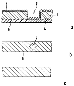
like, with
a substrate, on which are disposed at least two metal layers, the metal layers
having
different optical densities wherein each of the at least two metal layers has
gaps
formed therein that are not arranged in a completely congruent configuration,
consisting of the following stages: al) providing the substrate in the form of
a self-
supporting plastic film or in the form of a carrier material on which is
disposed a
plastic layer; bl) optionally, printing the substrate with alphanumeric
characters,
patterns, logos or the like using a printing ink with a high pigment content
and drying
the printing ink as to form a pored, raised applied ink layer; c 1) applying
the optically
thinner metal layer onto the, optionally, printed substrate; dl) printing the
optically
thinner metal layer with alphanumeric characters, patterns, logos or the like
using a
printing ink with a high pigment content and drying the printing ink as to
form a
pored, raised applied ink layer; el) applying the optically denser metal layer
onto the
CA 02483467 2011-07-29
- 2a -
optically thinner metal layer; fl) removing the applied ink layer and the
metal layer or
metal layers lying thereabove or having penetrated the applied ink layer, by
washing
out with a liquid, possibly combined with mechanical action; g 1) drying and,
optionally, cutting the substrate to size or a2) providing the substrate in
the form of a
self-supporting plastic film or in the form of a carrier material on which is
disposed a
plastic layer; b2) printing the substrate with alphanumeric characters,
patterns, logos or
the like using a printing ink with a high pigment content and drying the
printing ink as
to form a pored, raised applied ink layer; c2) applying the optically denser
metal layer
onto the printed substrate; d2) removing the applied ink layer and the metal
layer or
metal layers lying thereabove or having penetrated the applied ink layer, by
washing
out with a liquid, possibly combined with mechanical action; e2) applying the
optically thinner metal layer onto the optically denser metal layer; 12)
optionally,
cutting the substrate to size.
[0006] According to the invention the security element has a substrate,
onto which
at least two metal layers with different optical densities are disposed
preferably one
above the other and/or preferably on the same side of the substrate. At least
the layer
with a higher optical density preferably has gaps, i.e. that at least in a
partial area of
the substrate only the optically thinner layer of the at least two metal
layers with
different optical densities is present. In case the metal layers are disposed
one above
the other, the two metal layers adjoin each other in particular directly, i.e.
no further
layers lie between the metal layers. The optical impression rendered by such a
security
element can be imitated, if at all, only with great effort, in particular if
different-
coloured metal layers are applied in complicated patterns with exactly defined
layer
thicknesses, which possibly may also be intertwined with each other.
[0007] The metal layers have different optical densities, i.e. each
layer shows a
different transmission behaviour. The optically denser metal layer of the at
least two
metal layers, hereinafter referred to as metal layer A, shows a lower
transmission,
preferably a maximum transmission of 30 %, especially preferred a maximum of
%. The optically thinner metal layer of the at least two metal layers,
hereinafter
CA 02483467 2011-07-29
- 2b -
referred to as metal layer B, shows a higher transmission than layer A,
preferably more
than 10 %, especially preferred 25 to 80 %. Particularly attractive effects
are the result,
when the metal layer A has a maximum transmission of 10 % and the metal layer
B a
minimum transmission of 50 %.
100081 The metal layer A due to its lower transmission is perceived
opaque by the
viewer, while the metal layer B shows semitransparent properties.
CA 02483467 2004-10-25
-3-
100091 "Semitransparency" here means translucence, i.e. the layer shows a
light
transmission ratio of under 90 %, preferably between 80 % and 20 %.
[00101 The functional correlation between transmission T and optical density
OD
is formulated as follows:
OD = logT [%]
[00111 The transmission values are preferably determined within the visible
spectral region, especially preferred at a wavelength of 500 nm.
[00121 Furthermore, the optical density of a metal layer depends, among other
things, on the metal used and on the layer thickness. Depending on the kind of
metal
and on the transmission properties to be achieved, as a rough approximate
value for
metal layer A can be assumed a layer thickness of about 20 to 300 nm and for
metal
layer B a layer thickness of 2 to 20 nm.
[00131 The metal layers can be applied onto the substrate either side-by-
side,
overlapping or one above the other.
[00141 In principle, the layer order of the metal layers can be any desired
order.
The designations metal layer A and metal layer B do not represent the order
with
respect to a carrier, but shall merely permit an easier linguistic
differentiation between
a layer optically more dense and a layer optically less dense. For example,
with layers
lying one above the other at first the optically denser metal layer can be
applied and
then the optically thinner metal layer. However, the layer order can be vice
versa as
well. Which layer order is the more suitable one results from the individual
case.
10015] In the inventive embodiment the metal layers preferably are disposed
one
above the other. The metal layers disposed one above the other in particular
adjoin
each other directly, i.e. no further layer is disposed between the metal
layers A and B.
= 100161 The metal layers A and B can consist of the same material, but
also of
different materials. When combining different metals, the following color
CA 02483467 2004-10-25
- 4 -
- combinations are particularly suitable: gold-/silver-
coloured, gold-/copper-coloured,
chromium-/gold-coloured, chromium-/copper-coloured.
[00171 Suitable metals are, for example, aluminum, cobalt, copper,
gold, iron,
chromium, nickel, silver, platinum, palladium, titanium or other "nonferrous
metals"
and any alloys thereof such as e.g. Inconel, gold bronzes, silver bronzes etc.
For the
optically denser layer A preferably aluminum is used because of its small
penetration
depth for visible light and because it is easier to process, and gold, copper,
chromium,
silver or iron are used for the optically thinner layer B because of their
large
penetration depth for visible light and their characteristic colour.
100181 Some preferred material combinations are summarized in the
table shown
below.
T<10 % Alu Copper Gold Iron Chro- Nickel Silver Platinum Palla-
Inconel
layer A mium
dium
T > 50 %
layer B
Alu D/A 0 0 OM 0 M
0
Copper 0 D/A 0 OM 0 M 0 0 0 0
Gold 0 0 D/A OM 0 M 0 0 0 0
Iron 0 0 0 D/A
M 0 0 0
Chromium 0 0 0 D/A M D/A M
0 0 0
Nickel 0 0 OM 0 D/A
0
Silver 0 0 OM 0
D/A 0
Platinum 0 0 OM 0
D/A 0
Palladium 0 0 OM 0
D/A 0
Inconel 0 0 0 . M
0 - 0 0 0 D/A ,
T: transmission
0: visually easily perceptible colour contrast
CA 02483467 2004-10-25
- 5
M: with an appropriate thickness a machine-readable magnetism in layer
A is
the result
D/A: when viewed in incident light the security element appears
homogeneously
metallized; in transmitted light gaps are visible.
[0019] The forgery-proofness can be additionally increased, when the gaps,
i.e. the
places, where the optically denser layer is not present or which are metal-
free, do not
have an only simple form, but the form of alphanumeric characters, patterns,
logos or
the like, or are disposed in the form of a code, e.g. a bar code.
[0020] The optically denser metal layer when having an appropriate
thickness can
additionally have magnetic properties. When the gaps are disposed in a
suitable
fashion, even a machine-readable coding can be incorporated into the security
element.
[0021] The substrate of the security element preferably is a plastic film.
In
addition, the substrate can be provided with diffraction structures in the
form of a
relief structure. The diffraction structures can be any diffractive
structures, such as
holograms or grating structures (e.g. Kinegrams0, pixelgrams) or the like.
[0022] Furthermore, it is possible, that the substrate consists of films
laminated
together. In particular two films can be laminated together, one metal layer
at a time
being present on the outside of a film.
[0023] In the following are described the different variations of layer
material and
layer structure in combination with gaps and diffraction structures and their
different
forms of appearance. Of course, all variations can be combined with each other
in any
desired fashion.
Variation 1: Metal layers made of the same material
[0024] In this embodiment the metal layers A and B consist of the same
material.
For example, aluminum can be vapor-deposited onto the substrate as metal layer
A and
B. The different optical densities of the individual layers are achieved e.g.
via a
variation of the layer thickness.
CA 02483467 2004-10-25
- 6 -
[0025] The layer sequence in the security element reads, for example,
substrate,
optically thin metal layer B, optically dense metal layer A. Alternatively,
the layer
structure can read substrate, optically dense metal layer A, optically thin
metal layer B.
Preferably, all three layers lie directly one above the other and are not
separated from
each other by further layers. The optically dense metal layer A is not applied
all-over,
i.e. the opaquely appearing layer A has gaps.
[0026] When viewing this security element in transmitted light, the
areas not
covered with the opaquely appearing layer A are clearly recognizable as
transparent
areas. Depending on how the transmission properties of the optically thin
metal layer
B have been adjusted, the viewer, despite the metal coating B present in the
area of the
gaps of layer A, believes to perceive fully transparent areas or
semitransparent areas.
[0027] In incident light the security element appears as uniform all-
over-coated
surface. I.e. the gaps are not visible.
[0028] Beside the gaps in the metal layer A, there can be gaps in the
metal layer B,
too. Impressive effects are achieved, whenever the layers A and B lie one
above the
other and a part of the gaps in the metal layers A and B at least partially
lie one above
the other and preferably are disposed congruently, or lie one above the other
and
preferably the gaps in the metal layer A are larger than the gaps in the
semitransparent
metal layer B.
[0029] The gaps in one or in the two metal layers can be disposed in
any form,
combination and order.
[0030] Additionally, the security element can be equipped with
diffraction
structures. Preferably, these are incorporated at least into partial areas of
the substrate
surface, preferably embossed, the metal layers coming to lie on the substrate
surface
with the diffraction structures. Preferably, the coating order will be the
following:
substrate with diffraction structure / metal layer A / metal layer B.
[0031] The diffraction structures are particularly brilliantly visible
in those places,
where a metal layer is present, i.e. where is no gap. In the area of the gaps
in
CA 02483467 2004-10-25
- 7
transmitted light the diffraction structures are only slightly visible or not
visible. In
incident light the diffraction structures are visible in both the area of the
metal layer as
well as the area of the gaps.
Variation 2: Metal layers made of different materials
[0032] With this embodiment the metal layers A and B consist of different
materials. For example, aluminum can be vapor-deposited onto the substrate as
metal
layer A and gold as metal layer B. The different optical densities of the
individual
layers are achieved e.g. via a variation of the layer thickness and/or the
material.
[0033] The layer sequence within the security element and the disposition
of the
gaps in the individual layers can be the same as described in variation 1.
[0034] When viewing this security element in transmitted light, the gaps
in the
layer A are clearly recognizable as transparent areas. Depending on how the
transmission properties of the optically thin metal layer B have been
adjusted, the
viewer, despite the metal coating B present in the area of the gaps in layer
A, believes
to perceive fully transparent areas or semitransparent areas. Possibly, the
semitransparent areas stand out in colour against the surroundings due to the
different
materials in layer A and B.
[0035] In incident light the security element does not appear as a
uniform, all-over
coated surface, but shows another appearance in the areas not covered with the
optically denser metal, namely areas in the colour tone of the second metal.
I.e. the
gaps in the metal layer A are also visible in incident light and have the
colour of the
metal layer B.
[0036] Beside the gaps in the metal layer A, there can be gaps in the
metal layer B,
too. Impressive effects are achieved, whenever the layers A and B lie one
above the
other and a part of the gaps in the metal layers A and B at least partially
lie one above
the other and preferably are disposed congruently, or lie one above the other
and
preferably the gaps in the metal layer A are larger than the gaps in the
semitransparent
metal layer B.
CA 02483467 2004-10-25
-8-
100371 The gaps in one or in the two metal layers can be disposed in any form,
combination and order.
[0038] Additionally, the security element can be equipped with diffraction
structures. Preferably, these are incorporated at least into partial areas of
the substrate
surface, preferably embossed, the metal layers coming to lie on the substrate
surface
with the diffraction structures. Preferably, the coating order will be the
following:
substrate with diffraction structures / metal layer A / metal layer B.
[0039] The diffraction structures are particularly brilliantly visible in
those places,
where a metal layer is present, i.e. where is no gap. In incident light the
diffraction
structures are recognizable also on the places of the gaps.
[0040] The following description is not restricted to the variations 1 and 2,
but is to
be understood as a general description which applies to all embodiments
equally.
[0041] The security element can be a security thread, which consists of a self-
supporting plastic film to which the different metal layers are applied. This
security
thread can at least partially be incorporated into a security paper or
security document.
If the security thread is designed such that it looks identically irrespective
of whether
viewing front or back, not even the trueness to side needs to be taken into
account
when incorporating the security thread. It is also thinkable to form the
security element
in a ribbon-shaped or label-shaped fashion and to fasten it to the surface of
the security
paper or document of value.
[0042] Alternatively, the security element can also have the form of a
transfer
element or laminated film. This variation is particularly advantageous, if the
security
element is disposed completely on the surface of the security paper or
document of
value. In this case the layer structure of the security element is prepared on
a carrier
foil, usually a plastic film, and afterwards transferred in the desired
outline contours to
the security paper or document of value e.g. by means of a hot stamping
method.
CA 02483467 2010-09-09
- 9 -
[0043] If the security element is disposed on the surface of the security
paper or
document of value, it can have any outline structures, such as for example
round, oval,
star-shaped, rectangular, trapezoidal or strip-shaped outline contours.
[0044] According to a preferred embodiment the security paper or document
of
value, onto which the security element is applied, has a continuous opening.
Here the
security element is disposed in the area of the opening and protrudes it on
all sides.
[0045] In another preferred embodiment the security paper or document of
value
has a security element in the form of a security thread.
[0046] In both embodiments the security element can be checked from both
front
and back of the paper or document, which distinctly facilitates the
authentication
check even for an unpractised viewer.
[0047] Therefore, an imitation of the colour effect is particularly
complicated or
can be completely ruled out with these embodiments.
[0048] But the use of the inventive security element is not restricted to
the area of
security documents. The inventive security element can also be advantageously
used in
the field of product protection for protecting any goods from forgery. For
that purpose
the security element can have additional antitheft elements, such as for
example a coil
or a chip. The same applies to the security paper or document of value that is
provided
with such a security element.
[0049] The application of the metal layers preferably is effected by a
vapor
deposition unit, e.g. by means of sputtering or by means of an electron beam
vapor
deposition method.
[0050] The manufacturing of the gaps in the respective metal layers
preferably is
effected with the aid of a washing method as described in WO 99/13157. Here
the
security elements are prepared in the form of a security foil, which contains
a number
of simultaneous copies of the security element. The basic material is a self-
supporting,
preferably transparent plastic film.
CA 02483467 2004-10-25
- 10
This plastic film in the case of security threads or labels corresponds to the
inventive
plastic layer of the security element. When the security elements are
dissolved out
from an embossed film, the plastic film forms the carrier material of this
transfer
material, to which the plastic layer is applied in the form of a lacquer
layer. In this
lacquer layer or, in the case of security threads or labels, in the plastic
film can be
embossed diffraction structures. The inventive plastic layer of the security
element is
printed in the form of the future gaps, preferably by gravure printing. For
this a
printing ink with a high pigment content is used, which forms a pored, raised
applied
ink layer. Afterwards the different-coloured metal layers are vapor-deposited
onto the
printed plastic layer. As a last stage finally the applied ink layer and the
metal layer
lying on top of it are removed by washing out with a liquid, possibly combined
with
mechanical action. Preferably, a water-soluble printing ink is used, so that
water can
be used as liquid. Thus this method is very environmentally friendly and does
not
require any particular protective measures. Furthermore, this method has the
advantage, that the gaps in the two or several metal layers are manufactured
in one
single operation.
[0051] The washing out can be supported by mechanical means, such as a
rotating
roll, brush or ultrasound.
[0052] As an alternative to the vapor-deposition of the layers onto one
substrate,
the layers each can be applied to a separate substrate. Afterwards, the coated
substrates
are laminated together, preferably in such a way, that the coated sides of the
substrates
come to lie facing each other.
[0053] Due to the fact, that the inventive security element cannot be
imitated with
simple technical means and every attempt of replication is easy to detect, but
also due
to the visually distinctly perceptible colour effects and incident/transmitted
light
effects which are easily recognizable by a viewer, the inventive security
element
shows an enormously improved forgery-proofness. In particular the security
element
cannot be manufactured by the mere punching out of foil, etching away or
scraping off
CA 02483467 2004-10-25
- 11 -
= the metal layer, since the metallization technique and at the
same time exact control of
the layer thicknesses have to be mastered.
[0054] Further embodiments and advantages of the inventive security
element or
security paper and document of value are explained with reference to the
figures. The
Figures are schematic diagrams and do not necessarily correspond to the
dimensions
and proportions present in reality.
[0055] Fig. 1 shows an inventive document of value,
[0056] Fig. 2a shows layer structure and section through an
inventive
security element along the line A - A,
[0057] Fig. 2b shows the security element according to Fig.
2a in a top view
in transmitted light,
[0058] Fig. 2c shows the security element according to Fig.
2a in a top view
in incident light,
[0059] Fig. 3a shows layer structure and section through an
inventive
security element along the line A - A,
[0060] Fig. 3b shows layer structure and section through an
inventive
security element along the line A - A,
[0061] Fig. 4a shows layer structure and section through an
inventive
security element along the line A - A,
[0062] Fig. 4b shows the security element according to Fig.
4a in a top view
in transmitted light,
[0063] Fig. 4c shows the security element according to Fig.
4a in a top view
in incident light,
[0064] Fig. 5a shows layer structure and section through an
inventive
security element along the line A - A,
CA 02483467 2004-10-25
- 12 -
- [0065] Fig. 5b shows the security element
according to Fig. 5a in a top view
in transmitted light,
100661 Fig. 5c shows the security element according to Fig.
5a in a top view
in incident light,
[00671 Fig. 6a shows layer structure and section through an
inventive
security element along the line A - A,
100681 Fig. 6b shows the security element according to Fig.
6a in a top view
in transmitted light,
[0069] Fig. 6c shows the security element according to Fig.
6a in a top view
in incident light,
100701 Fig. 7a shows layer structure and section through an
inventive
security element along the line A - A,
[0071] Fig. 7b shows the security element according to Fig.
7a in a top view
in transmitted light,
100721 Fig. 7c shows the security element according to Fig.
7a in a top view
in incident light,
[00731 Fig. 8a shows layer structure and section through an
inventive
security element along the line A - A,
[00741 Fig. 8b shows the security element according to Fig.
8a in a top view
in transmitted light,
100751 Fig. 8c shows the security element according to Fig.
8a in a top view
in incident light,
[0076] Fig. 9a to 9e show a method for producing an inventive security
element,
CA 02483467 2004-10-25
- 13 -
. [00771 Fig. 10a to 13 show further variations of the inventive
security element in a
top view in transmitted light and in cross section.
100781 Fig. 1 shows an inventive document of value in a top view. The shown
example is a bank note 1. This bank note has a strip-shaped security element
2, which
extends across the entire width of the bank note 1 and spans a hole 3 in the
bank note.
The displayed security element is a security element that consists of a
plastic layer and
two metal layers of different optical densities. At least in the optically
denser layer,
optionally also in the optically thinner layer, are located the gaps. The
entire surface of
the security element 2 facing the viewer is coated according to the invention,
the
effects, in particular visually perceptible in the area of the hole 3, being
described in
the following Figures. For clarity's sake the following Figures each show a
layer
structure minimized to the basic inventive idea. Further layers, such as
adhesive layers
or laminated films used for protecting the surface etc., can of course be
present
additionally, and are to be added by the person skilled in the art depending
on the case
of application.
[00791 Fig. 2a in a detail view shows the cross section of the security
element 2
along the line A - A in Fig. 1 in a first embodiment. Here the plastic film 4
can be
recognized, which serves as a substrate for the metal layers to be vapor-
deposited. In
the plastic layer the diffraction structures 5 are incorporated.
Alternatively, the
diffraction structures could be incorporated in an additionally applied
lacquer layer. To
the side of the plastic film, where the diffraction structures are located, a
metal layer 6
is vapor-deposited directly adjoining, which is the optically denser metal
layer A and
which appears opaque when viewed. In the present embodiment the metal layer A
consists of aluminum. Thereabove again a metal layer 7 is located, namely the
optically thinner metal layer B, which also consists of aluminum. In the
layers 6 and 7
there are present the same diffraction structures as in plastic film 4.
Additionally, in
the layer 6 are located gaps 8, which are any characters, alphanumeric
characters,
patterns, logos or the like. The layer order substrate / layer A / layer B
results in
advantageously designed security elements, in particular when diffraction
structures
are contained in the substrate.
CA 02483467 2004-10-25
- 14 -
= [0080] Fig. 2b shows how the detail of Fig. 2a appears when viewed
in transmitted
light. When viewing the security element from the uncoated side of the
substrate 4, in
transmitted light the gap 8 is recognizable as a transparent area or as a
semitransparent
area. The gap 8, here in the form of a star, is all-over bordered by the
silver appearing
aluminum layer 6.
100811 Fig. 2c shows the same detail viewed in incident light. The gap 8 is
no
longer recognizable as such and the viewer is shown a seemingly all-over
homogeneously coated security element.
[00821 In Fig. 3a a further embodiment of an inventive security element is
shown
in cross section. Here the plastic film 4 at first is coated with an optically
thinner
aluminum layer 7, and thereabove is located an optically denser aluminum layer
6 with
gaps 8. Onto the optically denser aluminum layer 6 a second optically thinner
aluminum layer 7 is vapor-deposited. In the area of the gap 8 the two
optically thinner
aluminum layers 7 adjoin each other, the sum of the two layer thicknesses of
the two
aluminum layers 7 being lower than the layer thickness of the metal layer 6.
The
advantage of this embodiment is, that it is a symmetrical security element,
i.e.
irrespective of whether being viewed from front or back, the appearance is
always the
same.
[0083] In Fig. 3b an embodiment of an inventive security element is shown in
cross section, in which the optically denser layer 6 and the optically thinner
layer 7 are
not placed one above the other, but next to each other. At first a plastic
film 4 is only
partially coated with an optically thinner aluminum layer 7, e.g. in a strip-
shaped
fashion. In a second stage the optically denser aluminum layer 6 is applied to
the
spaces in between in exact register or slightly overlapping with layer 7. This
embodiment, too, shows the same appearance irrespective of whether viewed from
front or back. In transmitted light on the ribbon-shaped substrate the viewer
sees
alternating light and dark stripes extending crosswise thereto. In incident
light the
substrate appears uniformly silvery-coated.
CA 02483467 2004-10-25
- 15
100841 Fig. 4a shows a further embodiment in cross section. With this
variation at
first the optically thinner layer B and afterwards the optically denser layer
A is applied
onto the substrate 4, in contrast to the layer order in Fig. 2a. This layer
order is
preferably used for substrates not embossed. This embodiment is characterized
by the
fact, that the optically thinner layer and the optically denser layer are each
composed
of different metals. With respect to this no restraints are imposed upon a
person skilled
in the art. By way of example one possibility, representative for many others,
is
described with reference to Fig. 4a. On the substrate 4 in the left area of
the Figure is
located the optically thinner metal layer 9 made of aluminum and in the right
area of
the Figure is located the optically thinner metal layer 10 made of chromium.
On top of
the metal layer 9 made of aluminum is located a further aluminum layer 11,
though
designed as an optically denser layer. On top of the chromium coating is
located the
optically denser metal layer 12 made of gold. The optically denser layers made
of
aluminum and gold here are disposed in such a way, that a gap 8 is the result
in the
area where the optically thinner layers 9 and 10 adjoin each other.
100851 Fig. 4b shows the detail of the security element shown in Fig. 4a in
cross
section when viewed in transmitted light. When viewing the security element
from the
direction of the optically denser layer, in the left area of the image can be
seen the
silvery appearing area 13 and in the right area the gold-coloured appearing
area 14.
The gap 8 can be recognized as a transparent detail protruding into the area
11 as well
as into the area 12.
100861 Fig. 4c shows the same detail in incident light. In the left area of
the figure
the security element appears as all-over homogeneously silver-shining surface
13,
while in the right area of the figure 14 a silver-coloured partial area 15 is
visible,
which is for the most part surrounded by the gold-coloured area 14.
[0087] Fig. 5a shows a further embodiment of the inventive security element 2.
In
this variation both the optically thinner as well as the optically denser
metal layer are
made of aluminum. Onto the substrate 4 at first the optically thinner aluminum
layer 7
is applied, this layer already having a gap 16. Onto the optically thinner
aluminum
CA 02483467 2004-10-25
- 16 -
. layer 7 the optically denser aluminum layer 6 is applied in such
a way, that the gaps in
the optically denser layer 8 on the one hand come to lie congruently to the
gap 16 and
on the other hand are located above the optically thinner layer 7.
[0088] When viewing the security element of Fig. 5a in transmitted
light, to the
viewer appears, as shown in Fig. 5b, a silver-shining ribbon with transparent
areas,
which are designed on the one hand as a square 17 and on the other hand as a
circle 18.
[0089] As shown in Fig. 5c, in incident light a different image is
presented to the
viewer. Here the gap 16, which is congruent to gap 8, can still be perceived
as
transparent area 17, while the area 18 no longer is recognizable and the
security
element in this area presents itself as an apparently homogeneously coated
element.
[0090] Fig. 6a shows a further embodiment of the inventive security
element. In
this element, too, the optically thinner layer 7 and the optically denser
layer 6 are made
of the same material, namely aluminum. The gaps in both layers are disposed in
such a
way, that the gap 16 in the optically thinner layer and the gap 8 in the
optically denser
layer are disposed one on top of the other, the gap 8 being larger than the
gap 16. The
disposition of the layers on the substrate 4 corresponds to that shown in Fig.
5a. When
viewing this security element in transmitted light, as shown in Fig. 6b, the
viewer
perceives a transparent area 19, which corresponds to the outline form of the
gap 8.
Gap 16 is not recognizable as such.
[0091] When viewing this segment in incident light, as shown in Fig. 6c,
only gap
16 can still be perceived as a transparent area. Again, gap 8 is perceived as
a
homogeneous surface, which cannot be differentiated from the rest of the
opaque
layer.
[0092] To what extent the optically thinner layer 7 is perceived as
transparent or
semitransparent, depends on the respective materials and layer thicknesses.
These can
be adjusted depending on the desired effect by a person skilled in the art.
[0093] Fig. 7a shows an embodiment, which shows the same layer structure
as Fig.
5a, but differs from the embodiment of Fig. 5a in the fact that the optically
thinner
CA 02483467 2004-10-25
, layer 7 is made of copper and the optically denser
layer 6 is made of aluminum. In - 17 -
transmitted light, as shown in Fig. 7b, in the area of the gaps 8 and 16,
again,
transparent areas 20, 21 are recognizable. If desired, the transmission
property of the
copper layer can be adjusted in such a way, that the viewer does not perceive
a fully
transparent gap in the area 21, but recognizes a slightly greenish
semitransparent area.
In incident light, as shown in Fig. 7c, the gap 16 continues to be
recognizable as a
transparent area 20, while in the area of the gap 8, which lies on top of the
copper
layer, appears a circular-shaped, copper-coloured element 21 in silvery
surroundings.
[00941 Like in Fig. 6a in Fig. 8a is shown an embodiment, in
which the gap 8
comes to lie above the gap 16 and covers a larger area than the latter. In
contrast to the
embodiment in Fig. 6a, Fig. 8 shows a variation wherein the optically denser
layer 6
consists of aluminum and the optically thinner layer 7 of copper. The effect
perceptible
in transmitted light as shown in Fig. 8b, corresponds to that shown in Fig.
6b. I.e., the
transparent surface 22, which the viewer is able to perceive, corresponds to
the gap 8.
In incident light, however, Fig. 8c shows another form of appearance than the
one
described in Fig. 6c. Gap 16 is recognizable as a transparent area 23 in the
form of a
rectangle, while the gap 16 can be perceived as a copper-coloured triangle 22.
The rest
of the surface of the security element appears silver-coloured which is due to
the
aluminum layer.
[0095] Fig. 9a to 9e schematically display the method for
producing an inventive
security element as shown in Fig. 5a and 7a. The method is explained by way of
example for security threads or security labels, but, of course, can be used
analogously
for security elements with different layer sequences. The security elements
preferably
are produced in the form of a security foil, which contains a number of
simultaneous
copies of the security element. In the displayed example a self-supporting
plastic film
4 forms the basis. In a first stage, as shown in Fig. 9a, this film is printed
with a
strongly pigmented printing ink 24 in the areas where later the gaps 16, 8
shall be
present, so that a large-pored print is the result. Afterwards, the in this
case optically
thinner metal layer 7 made of aluminum is applied to the printed plastic film
4. This is
preferably effected by a vapor deposition method, with the help of which the
metals
CA 02483467 2004-10-25
- 18 -
are vapor-deposited one after the other, optionally via masks, onto the
plastic film 4. In
the area of the print 24 the formation of a continuous metal layer does not
take place,
which is due to the porous surface structure of the printing ink. The
intermediate
product provided with the metal layer 7 is displayed in Fig. 9b.
100961 With the first print of washable ink will be manufactured the gap 16
in the
embodiment shown in Fig. 5a and 7a. As to manufacture the gaps 8, again a
print 25
with washable ink is effected on the desired place. Fig. 9c here shows the
intermediate
product printed with the printing ink 24 and afterwards coated with aluminum
and
again printed with ink 25.
100971 This intermediate product then again is coated with metal, e.g. with
aluminum, so as to manufacture the optically denser layer 6 (see Fig. 9d).
100981 Since a formation of a solid metal surface does not take place in the
area of
the print 24 and 25, the print and the metal layer 6 or 6 and 7 present in
this area can
be removed nearly without difficulty by washing out. Preferably, water is used
for the
washing out. Possibly, it may become necessary to additionally use brushes,
which
ensure a complete removal of the print 24 and 25. The final product is shown
in Fig.
9e. The metal layers 6 and 7 have the gaps 8 and 16. Afterwards the security
foil can
be cut into security elements of the desired form.
100991 The washing method has the advantage that sharp and defined edges and
contours are achieved, so that with the help of this method also very fine
high-
resolution characters or patterns can be manufactured in the metal layers.
[0100] Fig. 10a to 13 show further variations of the inventive security
element,
gaps being combined to form positive text or negative text and maybe being
present in
one or both layers.
101011 Fig. 10a shows an embodiment, in which on the one hand the gaps 16
come
to lie in the optically thinner layer 7 congruently to the gaps 8 in the
optically denser
layer 6, and on the other hand the gap 8 in the optically denser layer is
substantially
larger than the gaps 16. By this explicit disposition of the gaps in
transmitted light to
CA 02483467 2004-10-25
- 19 -
' the viewer the writing "PL 2000" always appears as transparent
area, which is
disposed in an opaque field or in a semitransparent field. In Fig. 10b the
layer structure
of the security element shown in Fig. 10a can be seen in cross section. The
representation of the cross section here is restricted to the representation
of the two left
fields shown in Fig. 10a.
101021 In Fig. ha is shown an embodiment, in one area of which the gaps
in the
optically denser and the optically thinner layer come to lie congruently and
in a further
area the optically thinner layer is present all-over, while the gaps in the
optically
denser layer are designed in such a way that the writing "PL 2000" stands out
as
positive text against a semitransparent background. The pertinent layer
structure is
displayed in Fig. 11b, wherein again the two left fields of the security
element shown
in Fig. lla are displayed.
[0103] In Fig. 12a is displayed a security element, that has areas, in
which the
semitransparent writing "PL 2000" appears in opaque surroundings, while in
other
fields the opaque positive writing "PL 2000" appears in semitransparent
surroundings.
This appearance is achieved by the fact, that the optically thinner layer 7 is
present all-
over and the optically thicker layer 6 applied thereon with the desired gaps
is applied
with the aim of manufacturing a positive or negative text. Fig. 12b shows the
pertinent
layer structure of the two left fields shown in Fig. 12a.
101041 In Fig. 13 various gap variations shown in the previous Figures
are
combined with each other. In this security element a semitransparently
appearing
negative writing "PL 2000" is present in opaque surroundings, neighboured by a
semitransparent field, in which appears the opaquely appearing positive
writing
"PL 2000" which in turn is neighboured by an opaquely appearing field with the
transparently appearing writing "PL 2000". The layer structure of these three
fields
corresponds to the layer structure shown in Fig. 12b combined with the layer
structure
of the first field, which is shown in Fig. 11b.