Language selection

Search

Patent 2483808 Summary

Third-party information liability

Some of the information on this Web page has been provided by external sources. The Government of Canada is not responsible for the accuracy, reliability or currency of the information supplied by external sources. Users wishing to rely upon this information should consult directly with the source of the information. Content provided by external sources is not subject to official languages, privacy and accessibility requirements.

Claims and Abstract availability

Any discrepancies in the text and image of the Claims and Abstract are due to differing posting times. Text of the Claims and Abstract are posted:

  • At the time the application is open to public inspection;
  • At the time of issue of the patent (grant).
(12) Patent: (11) CA 2483808
(54) English Title: SLIDER BLOCK FOR PUSHER LUG
(54) French Title: COULISSEAU POUR PLATEAU-POUSSOIR
Status: Deemed expired
Bibliographic Data
(51) International Patent Classification (IPC):
  • B27B 25/04 (2006.01)
  • B65G 19/24 (2006.01)
(72) Inventors :
  • HENDERSON, DEANE (Canada)
  • WIGHT, GEOFF (Canada)
  • WILLEY, JASON (Canada)
  • HALVERSON, BRUCE G. (Canada)
(73) Owners :
  • USNR KOCKUMS CANCAR HOLDINGS ULC (United States of America)
(71) Applicants :
  • COE NEWNES/MCGEHEE ULC (Canada)
(74) Agent: BORDEN LADNER GERVAIS LLP
(74) Associate agent:
(45) Issued: 2007-12-04
(22) Filed Date: 2004-10-04
(41) Open to Public Inspection: 2005-07-08
Examination requested: 2005-12-07
Availability of licence: N/A
(25) Language of filing: English

Patent Cooperation Treaty (PCT): No

(30) Application Priority Data:
Application No. Country/Territory Date
10/752,585 United States of America 2004-01-08

Abstracts

English Abstract

An improved slider block is a length of flanged channel having a cut-out in the lower web of the channel to accommodate mounting a flat bar journalled in the cut-out. The flanged channel is resilient. The flanged channel has a length sufficient to cover the length of a base plate on which the flat bar is orthogonally mounted. The sides of the channel define a cavity having a depth corresponding to the thickness of the base plate. A pair of flanges extend inwardly over the cavity from the sides of the channel so as to define a chain-receiving slot therebetween. The base plate mounts within the cavity. The base plate is welded to a chain so that when the base plate is mounted in the cavity the chain is mounted in and along the chain-receiving slot.


French Abstract

Un bloc coulissant amélioré est une longueur de canal à bride présentant une découpe dans la bande inférieure du canal pour recevoir le montage d'une barre plate tourillonnée dans la découpe. Le canal à bride est élastique. Le canal à bride a une longueur suffisante pour couvrir la longueur d'une plaque de base sur laquelle la barre plate est montée orthogonalement. Les côtés du canal définissent une cavité ayant une profondeur correspondant à l'épaisseur de la plaque de base. Une paire de brides s'étendent vers l'intérieur au-dessus de la cavité à partir des côtés du canal de manière à définir une fente de réception de chaîne entre eux. La plaque de base est montée à l'intérieur de la cavité. La plaque de base est soudée à une chaîne de telle sorte que lorsque la plaque de base est montée dans la cavité dans laquelle la chaîne est montée et le long de la fente de réception de chaîne.

Claims

Note: Claims are shown in the official language in which they were submitted.


WHAT IS CLAIMED IS:

1. An improved slider block for mounting on a chain mounted pusher lug, the
slider block
comprising:
a flanged channel having a lug receiving slot and a cut-out cooperating
therewith in a
lower web of said flanged channel to accommodate mounting a flat bar of the
pusher
lug journalled in said cut-out,
wherein said flanged channel is resilient and covers the length of a base
plate of the
pusher lug on which the flat bar is orthogonally mounted,
wherein opposite sides of said channel define a cavity having a depth
corresponding to
a thickness of the base plate,
and wherein a pair of flanges extend inwardly in opposed facing relation over
said
cavity from said sides of said channel so as to define a chain-receiving slot
therebetween, so that when the base plate is mounted within said cavity, the
chain on
which the base plate is mounted mates in and along the chain-receiving slot,
and the
flat bar mates in the cut-out.
2. The slider block of claim 1 wherein said cut-out has first and second
opposite ends
lying along a cut-out axis parallel to the long axis of the chain when the
pusher lug is
mounted in said slider block, said cut-out axis equi-distant between said
sidewalls of
said flanged channel, and wherein said first end of said cut-out is closed-off
so that an
adjacent portion of said lower web is continuous, extending between said
sidewalls and
between said first end of said cut-out and an adjacent first end of said lower
web so as
to form a resilient hinge in a plane containing said lower web,

6


and wherein an opposite second end of said cut-out is open-ended by said
pusher lug
receiving slot.
3. The slider block of claim 2 wherein said pusher lug receiving slot is
generally parallel
to said side walls and extends from said second end of said cut-out to an
adjacent
second end of said lower web so as to receive the flat bar of the pusher lug
slid along
and into said cut-out.
4. The slider block of claim 3 wherein said pusher lug receiving slot has a
width, being
the spaced distance between an opposed facing pair of edges defying said
pusher lug
receiving slot, which is less than the thickness of the flat bar, wherein said
pusher lug
receiving slot opens resiliently, by deformation of said lower web about said
pusher lug
receiving slot and said resilient hinge, to receive the flat bar as it is slid
into said cut-
out, and said pusher lug receiving slot closes resiliently behind the flat bar
once the flat
bar is mounted within said cut-out.

7

Description

Note: Descriptions are shown in the official language in which they were submitted.


CA 02483808 2004-10-04
SLIDER BLOCK FOR PUSHER LUG
Field of the Invention
a
This invention relates to the field of pusher lug lumber conveyors employed in
the lumber industry, and in particular to an improvement to pusher lug slider
blocks.
It is common practice in lumber processing facilities such as sawmills to
transport lumber over the top of sorter bins by overhead chain conveyors
equipped with pusher
lugs. Chain conveyors for the movement of lumber have links which each have an
upstanding
lug mounted thereon, spaced at intervals along the chain. Movement of the
chain brings the
lug into contact with the lumber, which is then urged in the direction of the
running of the
chain. When the lumber is located over a desired bin, a gate corresponding to
that bin opens
allowing the lumber to fall into that bin. Conventionally, a slider block is
rigidly mounted to
the chain where the pusher lugs attach to the chain to facilitate sliding
translation of the lugs
along the conveyor. Typically, fasteners attach the slider block to the chain,
requiring that the
chain links be pre-drilled where the slider blocks are to be fastened. Thus,
the process of
attaching the slider blocks to the chain is time consuming and costly.
It is consequently an object of the present invention to provide a slider
block
that requires no pre-drilling of the chain and no fasteners for mounting of
the slider block onto
the chain and pusher lug. It is a further object of the present invention to
provide for the
efficient installation and repla~cernent of slider blocks.
1


CA 02483808 2004-10-04
Summary of the Invention
In summary, the improved slider block of the present invention is a length of
flanged channel having a cut-out in the lower web of the channel to
accommodate mounting a
flat bar journalled in the cut-out. The flanged channel is resilient. The
flanged channel has a
length sufficient to cover the length of a base plate on which the flat bar is
orthogonally
mounted. The sides of the channel define a cavity having a depth corresponding
to the
thickness of the base plate. A pair of flanges extend inwardly over the cavity
firm the sides of
the channel so as to define a chain-receiving slot therebetween. The base
plate mounts within
the cavity. The base plate is welded to a chain so .that when the base plate
is mounted in the
cavity the chain is mounted in and along the chain-receiving slot.
The cut-out has first and second opposite ends lying along a cut-out axis
parallel to the long axis of the chain. The cut-out axis is equi-distant
between the sidewalk of
the flanged channel. The first end of the cut-out is closed-off so that the
adjacent portion of
the lower web is continuous, extending between the sidewalk and between the
first end of the
cut-out and the adjacent first end of the lower web so as to form a resilient
hinge in a plane
containing the lower web. The opposite second end of the cut-out is open-
ended. A flat bar-
receiving slot is generally parallel to the side walls and extends from the
second end of the cut-
out to the adjacent second end of the lower web so as to receive a flat bar
slid along into the
cut-out. The flat bar receiving slot has a width, that is the spaced distance
between the
opposed facing edges of the slot, which is less than the thickness of the flat
bar. Thus the flat
bar-receiving slot must open resiliently, by deformation of the lower web
about the slot and
the resilient hinge, to receive the flat bar as it is slid into the cut-out.
The flat bar-receiving
closes resiliently behind the flat bar once the flat bar enter into the cut-
out.
2


CA 02483808 2004-10-04
Brief Description of the Drawings
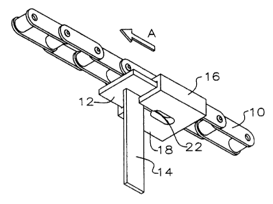
Figure 1 is an isometric view of the slider block of the present invention
mounted on a chain and pusher lug.
Figure 1 a is the slider block of Figure 1 in top perspective view.
Figure 2 is an isometric view of the slider block of to the present invention
being slide on to the pusher lug of Figure 1.
Figure 3 is a vertical sectional view through a chain run, orthogonally to the
longitudinal axis of the chain of Figure 1, showing the slider block and
pusher lug of Figure 1
within the confines of the chain run.
Figure 4 is a vertical sectional view through a chain return showing the
slider
block and pusher lug of Figure 1 sliding over the chain return.
Figure 5 is the lower surface of the slider block of Figure 1.
Detailed Description of Embodiments of the Invention
With reference to the drawing figures wherein similar characters of reference
denote corresponding parts in each view, as seen in Figures 1 and 2, a length
of chain 10 has
plate 12 welded to it. A rigid flat bar 14 is welded to plate 12 so as to
extend orthongally from
the plate. The piste and flat bar form a pusher lug. A plurality of pusher
lugs are mounted in
spaced array along the length of the chain. Only one of the pusher lugs is
illustrated. Bar 14 is
welded to the plate so that it protrudes downwardly orthogonally from the
plate to collectively
forma T-shape in vertical cross-section. The plate is welded to the chain.
3


CA 02483808 2004-10-04
Slider block 16 is made of wear-resistant resilient material such as plastic
or
other malleable solids. In one embodiment, block 16 is a flanged channel
sleeve or envelope
(collectively referred to as a flanged channel) so that block 16 slides snugly
and completely
over plate 12, save and except for where plate 12 is welded to chain 10, as
seen in the sectional
views of Figures 3 and 4. As seen in Figure 5, the lower surface 18 of slider
block 16 has an
elongate or obround aperture 20 machined or formed into it. A pusher lug
receiving slot 22
connects aperture 20 to one edge of slider block 16. The width of slot 22 is
smaller than the
thickness of the flat bar 14. When slider block 16 is urged in direction A as
shown in Figure 2,
such that slot 22 abuts the narrowest side of flat bar 14, slot 22 is
resiliently deformed and
opens or spreads apart to accommodate flat bar 14 and permit flat bar 14 to
enter aperture 20.
Once slider block 16 is in position such that flat bar 14 is contained within
aperture 20, slot 22
resiliently returns to its un-deformed state and thus seals and retains slider
block 16 on plate
12.
In operation, chain 10, plates 12 and slider blocks 16 run along the inner
lowermost surfaces inside a chain run 24. Chain run 24 is suspended from
above, as seen in
Figure 3. The lower surface of slider block 16 is contoured to match the
contour of the inner
lowermost surface of the chain run. Flat bar 14 protrudes downwardly from a
slot in the
lowermost surfaces of chain run 24. As chain 10 is run in a direction along
its longitudinal
axis opposite to direction A, slider block 16 slides along the inner surface
of chain run 24,
dragged along by flat bar 14, that is, chain 10 is run in a direction such
that flat bar 14 pushes
against the closed end of aperture 20 and not against slot 22. On an endless
chain, at the end
of the chain run, the pusher lug and slider block 16 are returned along chain
return 26, as seen
in Figure 4. Chain return 26 is a channel in which chain 10 is run, slider
block 16 carrying
plate 12 and flat bar 14 over the upper surface of the channel.
As will be apparent to those skilled in the art in the light of the foregoing
disclosure, many alterations and modifications are possible in the practice of
this invention
4


CA 02483808 2004-10-04
without departing from the spirit or scope thereof. Accordingly, the scope of
the invention is
to be construed in accordance with the substance defined by the following
claims.

Representative Drawing
A single figure which represents the drawing illustrating the invention.
Administrative Status

For a clearer understanding of the status of the application/patent presented on this page, the site Disclaimer , as well as the definitions for Patent , Administrative Status , Maintenance Fee  and Payment History  should be consulted.

Administrative Status

Title Date
Forecasted Issue Date 2007-12-04
(22) Filed 2004-10-04
(41) Open to Public Inspection 2005-07-08
Examination Requested 2005-12-07
(45) Issued 2007-12-04
Deemed Expired 2022-10-04

Abandonment History

There is no abandonment history.

Payment History

Fee Type Anniversary Year Due Date Amount Paid Paid Date
Registration of a document - section 124 $100.00 2004-10-04
Application Fee $400.00 2004-10-04
Registration of a document - section 124 $100.00 2005-08-12
Request for Examination $800.00 2005-12-07
Maintenance Fee - Application - New Act 2 2006-10-04 $100.00 2006-09-07
Registration of a document - section 124 $100.00 2007-02-14
Final Fee $300.00 2007-08-01
Maintenance Fee - Application - New Act 3 2007-10-04 $100.00 2007-09-20
Maintenance Fee - Patent - New Act 4 2008-10-06 $100.00 2008-10-03
Registration of a document - section 124 $100.00 2009-07-17
Maintenance Fee - Patent - New Act 5 2009-10-05 $200.00 2009-10-02
Maintenance Fee - Patent - New Act 6 2010-10-04 $200.00 2010-09-03
Maintenance Fee - Patent - New Act 7 2011-10-04 $200.00 2011-09-13
Maintenance Fee - Patent - New Act 8 2012-10-04 $200.00 2012-09-13
Maintenance Fee - Patent - New Act 9 2013-10-04 $200.00 2013-09-04
Maintenance Fee - Patent - New Act 10 2014-10-06 $250.00 2014-09-10
Maintenance Fee - Patent - New Act 11 2015-10-05 $250.00 2015-09-09
Maintenance Fee - Patent - New Act 12 2016-10-04 $250.00 2016-09-14
Maintenance Fee - Patent - New Act 13 2017-10-04 $450.00 2017-10-09
Maintenance Fee - Patent - New Act 14 2018-10-04 $250.00 2018-10-01
Maintenance Fee - Patent - New Act 15 2019-10-04 $450.00 2019-09-27
Maintenance Fee - Patent - New Act 16 2020-10-05 $450.00 2020-09-25
Maintenance Fee - Patent - New Act 17 2021-10-04 $459.00 2021-09-24
Registration of a document - section 124 2021-10-25 $100.00 2021-10-25
Registration of a document - section 124 2021-11-05 $100.00 2021-11-05
Owners on Record

Note: Records showing the ownership history in alphabetical order.

Current Owners on Record
USNR KOCKUMS CANCAR HOLDINGS ULC
Past Owners on Record
COE NEWNES/MCGEHEE INC.
COE NEWNES/MCGEHEE ULC
HALVERSON, BRUCE G.
HENDERSON, DEANE
USNR/KOCKUMS CANCAR COMPANY
WIGHT, GEOFF
WILLEY, JASON
Past Owners that do not appear in the "Owners on Record" listing will appear in other documentation within the application.
Documents

To view selected files, please enter reCAPTCHA code :


To view images, click a link in the Document Description column. To download the documents, select one or more checkboxes in the first column and then click the "Download Selected in PDF format (Zip Archive)" or the "Download Selected as Single PDF" button.

List of published and non-published patent-specific documents on the CPD .

If you have any difficulty accessing content, you can call the Client Service Centre at 1-866-997-1936 or send them an e-mail at CIPO Client Service Centre.


Document
Description 
Date
(yyyy-mm-dd) 
Number of pages   Size of Image (KB) 
Cover Page 2005-06-17 1 39
Abstract 2004-10-04 1 23
Description 2004-10-04 5 192
Claims 2004-10-04 2 66
Drawings 2004-10-04 3 58
Representative Drawing 2005-06-10 1 9
Cover Page 2007-11-13 1 40
Correspondence 2008-10-10 1 15
Correspondence 2009-09-22 1 17
Correspondence 2009-09-22 1 14
Correspondence 2009-01-13 6 218
Correspondence 2005-10-19 1 14
Fees 2006-09-07 1 35
Assignment 2004-10-04 8 377
Assignment 2005-08-12 122 4,906
Assignment 2005-09-06 3 159
Prosecution-Amendment 2005-12-07 1 33
Assignment 2007-02-14 59 2,052
Correspondence 2007-08-01 1 33
Fees 2007-09-20 1 36
Correspondence 2008-07-24 6 193
Correspondence 2008-10-10 5 176
Correspondence 2008-09-09 5 175
Correspondence 2009-01-13 5 191
Fees 2008-10-03 2 71
Assignment 2009-07-17 5 196
Correspondence 2009-07-17 10 365
Fees 2009-10-02 1 201
Fees 2011-09-13 1 39
Correspondence 2012-07-16 6 273
Correspondence 2012-07-31 1 14
Correspondence 2012-07-31 1 22