Note: Descriptions are shown in the official language in which they were submitted.
CA 02483964 2011-04-04
1
Monitoring Medical Gas Xenon Concentration using Ultrasonic Gas Analyser
Field of the Invention
The present invention relates to a method and apparatus using the gas
specific property of speed of sound for monitoring the concentration of xenon
in a
medical gas mixture with oxygen and, optionally, nitrogen recirculating
through a
medical device introducing carbon dioxide into the mixture.
Background of the Invention
Apparatus and methods for determining the concentration of components in
gas mixtures using sonic or ultrasonic transmission/detection systems are
known.
The concentration can be determined by phase or pulse measurements (see, for
example, US-A-6192739) and it is known to use the time for a pulse to be
reflected
one or more times across an internally reflective housing having the
transmitter and
receiver located at the same or different ends of the housing.
For example, US-B-5060514 discloses an ultrasonic gas measuring device
which has a cylindrical housing having transmitting and receiving means
provided on
opposite end walls of the housing. Gas flows axially through the housing from
an
inlet in the end wall having the transmitter to an outlet in the opposite end
wall. At
least at some instance during its flow through the housing, the gas flow is
divided so
as to reduce gas flow turbulence. Electronic circuitry in the device is
designed to
generate a signal corresponding to the ultrasonic radiation detected having
passed
through the gas sample, which is compared with a reference signal provided to
the
transmitting transducer and the resulting phase shift used to compute the
concentration of the gas. The device is particularly applicable to the
analysis of
oxygen concentration in medical devices used by respiratory patients.
In another example, US-B-6279378 discloses an apparatus and method
utilizing high frequency ultrasonic waves, especially of about 0.5 MHz, for
analysing
gases so as to measure trace amounts of gases in an air sample. The sample is
drawn through an acoustic chamber using a low speed air pump and the sound
velocity and acoustic attenuation of sound waves travelling through
CA 02483964 2004-10-26
WO 03/093812 PCT/GB03/01877
-2-
the gas/air mixture compared with that of air alone. The acoustic chamber of
the
device is small, the exemplified distance between a pair of transmitters/
receivers typically being 0.64cm but the wave is reflected back and forth
across
the chamber several times, for example five reflections. The speed of sound
and
the time of flight (TOF) over 11.43 cm is listed for several gases, including
xenon, together with the difference in TOF as compared with air alone.
Xenon has long been known as an anaesthetic gas used in admixture
with oxygen and optionally also helium, but has not been extensively used as
such. More recently, there has been interest in other medical uses for xenon.
In
particular, WO-A-0053192 discloses the use of xenon to treat
neurointoxications
such as caused by apoplexy, drug abuse, oxygen deficiency during birth,
Parkinson's disease, schizophrenia, Giulles de la Tourette syndrome,
craniocerebral trauma or migraine and refers to the use of xenon in a cardio-
pulmonary bypass machine. Further, WO-A-0108692 discloses the use of xenon
as an NMDA antagonist to, for example, provide neuroprotection, relieve
neuropathic pain or inhibit synaptic plasticity.
Xenon has limited availability in that it is usually extracted from air, in
which it constitutes only 0.000039 percent by weight (0.0000087 percent by
volume). Accordingly, it is desirable to recover or reuse xenon in any
application
and the need for such recovery or reuse will increase with increasing demand
for
xenon. In particular, it is desirable to recirculate xenon through medical
devices.
However, it is necessary to carefully monitor, and adjust, the xenon
concentration in a recirculating medical gas and hence the need exists for a
simple and relatively inexpensive means for providing a rapid and reasonably
accurate monitoring of xenon concentration in recirculating medical gas.
Although ultrasonic methods have been proposed to measure xenon
concentration as a contaminant, the active concentration of xenon in medical
gases is substantially higher than contaminant level and the presence of
carbon
dioxide introduced by the medical device would interfere with xenon
concentration measurements using ultrasonic measurements.
CA 02483964 2011-04-04
3
Summary of the Invention
According to a first aspect of the invention there is provided a method of
monitoring the concentration of xenon in a medical gas mixture recirculating
through
a medical device in which carbon dioxide is introduced into the mixture
resulting in a
carbon dioxide-contaminated gas mixture, said medical gas having xenon as an
active component and being selected from oxygen-containing mixtures consisting
of
oxygen and xenon and mixtures of xenon with a composition consisting of oxygen
and nitrogen and/or helium in known proportions, said method comprising
removing
carbon dioxide from said carbon dioxide-contaminated gas mixture downstream of
the medical device to provide a carbon dioxide-free gas mixture and
subsequently
upstream of the medical device the concentration of xenon is monitored by
measuring the time delay between transmission of an ultrahigh ultrasonic pulse
of at
least about 100 kHz axially through the carbon dioxide-free gas mixture in an
internally reflective cylindrical sample chamber from a location at one end
thereof
and reflection of said pulse axially from the other end of the chamber back to
said
location.
In a second aspect, the present invention provides an apparatus for
recirculating a medical gas mixture selected from oxygen-containing mixtures
consisting of oxygen and xenon and mixtures of xenon with a composition
consisting
of oxygen and nitrogen and/or helium in known proportions, through a medical
device in which carbon dioxide is introduced into the mixture resulting in a
carbon
dioxide-contaminated medical gas mixture, said apparatus comprising:-
a circuit for recirculatory flow of the medical gas mixture to and from said
medical device;
a carbon dioxide absorber downstream from the medical device for removing
carbon dioxide from the carbon dioxide-contaminated medical gas mixture to
provide
a carbon dioxide-free gas mixture;
an analyser upstream of the medical device for monitoring the concentration
of xenon in the carbon dioxide-free medical gas mixture recirculating within
the
circuit; said analyser comprising:-
an internally reflective cylindrical sample chamber having a gas inlet,
CA 02483964 2011-04-04
4
an ultrahigh frequency ultrasonic transmitter located at one end of the
sample chamber for emitting ultrasonic pulses of at least about 100 kHz
axially through the sample chamber,
a receiver located at said end of the sample chamber for receiving
ultrasonic radiation reflected axially from the other end of the sample
chamber, and
processing means for determining the time delay between transmission
and receipt of an ultrasonic pulse by said transmitter and receiver
respectively
and correlating said delay with reference data to indicate the concentration
of
xenon in the medical gas mixture in the sample chamber, and
gas replenishment means for introducing make-up gas components to
the medical gas mixture to control the constitution thereof.
Detailed Description of the Invention
Usually, the gas replenishment means will comprise separate respective inlets
into the recirculatory circuit for oxygen and for a xenon/oxygen mixture and,
optionally, a separate inlet into the recirculatory circuit for air.
Volumetric means may be provided for monitoring the volume of the carbon
dioxide-free medical gas mixture in the recirculatory circuit and/or an
analyser for
monitoring oxygen concentration in the carbon dioxide-free medical gas mixture
in
the recirculatory circuit. When the recirculating gas comprises nitrogen
and/or
helium additional mean usually will be provided for monitoring their
concentration.
In a third aspect of the invention, there is provided an analyser for use in
the
method of the invention, said analyser comprising:-
an internally reflective cylindrical sample chamber having a gas inlet and a
gas outlet located at axially and peripherally spaced locations in the side
walls
thereof with the gas inlet behind the transmitting surface of the transmitter
whereby
flow of gas through the chamber has an axial component;
an ultrahigh frequency ultrasonic transmitter located at one end of the sample
chamber for emitting ultrasonic pulses of at least about 100 kHz axially
through the
sample chamber,
a receiver located at said end of the sample chamber for receiving ultrasonic
radiation reflected axially from the other end of the sample chamber; and
CA 02483964 2004-10-26
WO 03/093812 PCT/GB03/01877
-5-
processing means for determining the time delay between transmission
and receipt of an ultrasonic pulse by said transmitter and receiver
respectively
and correlating said delay with reference data to indicate the concentration
of the
xenon in a gas mixture in the sample chamber.
The analyser preferably operates at a pressure of up to about 250 millibar
gauge (mbarg) (125 kPa), more preferably up to about 150 mbarg (115 kPa) and
the apparatus may provide gas to the medical device at a pressure of up to
about 100 mbarg (110 kPa), but preferably about 30 mbarg (103 kPa).
The transmitter and receiver may be separate but preferably a single
combined transmitter/receiver is used.
The frequency of the ultrahigh ultrasonic radiation used in the method is
greater than about 100 kHz and more preferably greater than about 250 kHz.
Preferably, the frequency is less than about 400 kHz and still more preferably
about 380 kHz. The use of ultrahigh ultrasonic radiation allows a very narrow
beam of pulses to be transmitted, which minimizes multiple reflections and
thus
improves the accuracy of the measurement. It also enables the sample
chamber to be minimized in size whilst maintaining the desired level of
accuracy
in the measurement.
Preferably the sample chamber is made from a polished low thermal
expansion material and is preferably of circular cross section. It also is
preferred
to have a volume of less than about 500 cm3 and more preferably less than
about 200 cm3
Preferably, the measurement of the content of gas is of an accuracy of
less than about 5%, more preferably less than about 2%, still more
preferably
3 0 less than about 1 % and most preferably less than about 0.5%.
CA 02483964 2004-10-26
WO 03/093812 PCT/GB03/01877
-6-
The accuracy of measurement is dependent on inter alia the path length
of the pulse, the overall volume of the sample chamber and the frequency of
the
ultrahigh ultrasonic radiation. However, if minimizing the size of the sample
chamber is important in the use of the analyser, such as to provide rapid
information regarding changes in the composition of a circulating medical gas
mixture, the level of accuracy may be compromised to enable rapid analysis of
the composition.
Preferably, in order to reduce the risk of affecting the measurement by
to refractive deflection of the beam, as may occur if a jet of gas from the
gas inlet is
introduced directly toward the transmitting surface of the transmitter, the
gas
inlet to the sample chamber is behind the transmitting surface. More
preferably,
the gas inlet and gas outlet to the sample chamber are located at axially and
peripherally spaced locations in the side walls of thereof whereby flow of gas
though the chamber has an axial component.
The accuracy of the measurement provided by the method and apparatus
of the invention is only slightly affected by small variations in temperature
and
readily can be approximately corrected by a correction signal derived from a
temperature sensitive electronic component. Similarly, provided that a
reasonable gas flow pattern is achieved, it is believed that the measurement
is
not significantly affected by variations in flow rate. However, in order to
maximize the accuracy in the measurement, the device may be calibrated before
use by passing pure xenon through the sample chamber at approximately the
flow rate to be used.
The method and apparatus of the present invention is particularly
applicable to the measurement of gas mixtures used in cardiopulmonary bypass
oxygenators or artificial ventilators.
When, as often in the case of spent medical gases, the gas mixture
contains, in addition to carbon dioxide, water vapour and/or other components
CA 02483964 2011-04-04
7
which absorb energy at high ultrasonic frequencies, it is usually necessary to
remove, or at least reduce, the content of said components prior to analysis
to
prevent interference with the analysis.
Brief Description of the Drawings
The following is a description by way of example only and with reference to
the accompanying drawings of presently preferred embodiments of the invention.
In
the drawings:-
Figure 1 is a cross-sectional side view of an analyser in accordance with the
present invention; and
Figure 2 is a diagrammatic representation of the use of the analyser of Figure
1 in a gas recirculation system for providing gas to a cardiopulmonary bypass
oxygenator.
Detailed Description of the Drawings and Preferred Embodiment
With reference to Figure 1, the gas analyser (generally designated 1) for
determining the composition of a gas mixture comprises a hollow internally
smooth
stainless steel cylinder 17, which defines a sample space 2 for the sample of
gas to
be analysed, and has a gas inlet 3 and a gas outlet 5 and an aperture 7. An
ultrahigh frequency ultrasonic gauge 11 is held in aperture 7 by ring seal 9
and the
opposing wall 15 of the cylinder 17 reflects ultrasonic pulses emitted by the
gauge.
The gauge 11 comprises a transducer 13, for emitting ultrasonic radiation, on
the
lowermost surface 19 of gauge 11. The transducer also acts as an ultrasonic
receiver and is connected to a microprocessor (not shown) for linearizing the
data
generated by the analyser.
In use, the analyser is used to measure the proportion of a gas in a mixture,
preferably oxygen and xenon, by emitting ultrasonic radiation at 380 kHz from
transducer 13 through the sample chamber 2, which contains the gas mixture
passing through the device via gas inlet 3 and gas outlet 5, and receiving the
radiation reflected from opposing wall, with receiver 19. The data is
CA 02483964 2004-10-26
WO 03/093812 PCT/GB03/01877
-8-
transferred to the microprocessor where it is manipulated to show the relative
proportions of gases in the mixture.
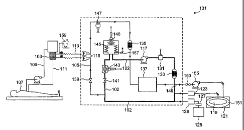
With reference to Figure 2, a xenon/oxygen mixture in a ratio of 80%
xenon to 20% oxygen is fed into the main circuit 102 of the apparatus
(generally
designated 101) from a xenon/oxygen supply in fresh gas space 119 of container
121 via xenon mass flow controller (MFC) 123.
The oxygen content of main circuit 102 is topped up from oxygen cylinder
125 via regulator 127 and oxygen mass flow controller (MFC) 129.
One or more (preferably four) diaphragm pumps 117 pump the
xenon/oxygen mixture around the circuit 102 at a rate of up to 20 litres per
minute (1/min) at a pressure of up to 150 millibar gauge (115 kPa).
The gaseous composition is fed to cardiopulmonary bypass (CPB)
oxygenator 103 via medical device supply conduit 105, which is regulated by
flow control valve 139, which may be set at a desired level by the operator.
CPB oxygenator 103, which is typically a membrane oxygenator, is fed
unoxygenated blood from a patient 107 via unoxygenated blood conduit 109 and
returned to the patient 107 via oxygenated blood conduit 111. Spent gas from
the CPB oxygenator 103 is fed through spent gas return conduit 113 and then
through water trap 147 and primary carbon dioxide absorber 135 to return to
the
main circuit 102 upstream of pump(s) 117.
Gas passing through the spent gas return conduit 113 and medical device
supply conduit 105 pass through respective bacterial filters 115 to protect
the
patient 107 from contamination from the apparatus 101 and vice versa.
In order to ensure that a constant flow of gas at the set pressure is
supplied to the oxygenator 103 and thus available to the patient's blood, gas
CA 02483964 2004-10-26
WO 03/093812 PCT/GB03/01877
-9-
circulates through the main circuit 102 via pressure maintaining valve 141
downstream from the outlet to medical device supply conduit 105. Pressure
maintaining valve 141 is a valve which allows gas flow only when the pressure
exceeds a predetermined level, for example 30 mbarg (103 kPa) and accordingly
maintains a constant pressure between the pumps 17 and the valve 141.
Downstream from the pressure maintaining valve 141, the gaseous
composition is analysed for xenon content using the ultrasonic xenon analyser
143 of Figure 1. In an alternative arrangement (not shown) the xenon analyser
is
located upstream of the pressure maintaining valve 141.
The gas is then fed via bellows 145, which expand to take up any
additional volume of gas in the apparatus or contract to compensate for loss
of
volume in the apparatus, and receives the spent gas upstream of pump(s) 117.
The oxygen concentration in the main circuit 102 is monitored by oxygen
fuel cell sensor 131 that is shown situated in the main circuit 102 downstream
from pump(s) 117 but could be located downstream of the pressure maintenance
valve 141. The gas is then fed through backup carbon dioxide absorber 133,
which removes residual carbon dioxide from the recirculating gas. The carbon
dioxide removed by absorbers 133 and 135 has entered via the oxygenator 103
after being flushed from the patient's blood. At least absorber 135 should be
replaced with each use of the system.
Downstream from the backup carbon dioxide absorber 133, a small
sample of gas is drawn from the main circuit 102 and fed to analyser unit 137
to
be analysed for carbon dioxide, via an infra red gas analyser, to ensure that
the
carbon dioxide absorbers are working efficiently and for oxygen, via a
paramagnetic gas analyser, as a backup to the oxygen fuel cell sensor 131. The
sample is returned to the main circuit 102 upstream from the pump(s) 117.
CA 02483964 2011-04-04
Recovery gas conduit 149 selectively feeds at least a portion of gas from the
main circuit 102 at a point downstream from the backup carbon dioxide absorber
133
to the ullage space 151 of container 121, via recovery valve 153 and
compressor
155. This container 121 is of the kind described in our co-pending UK Patent
5 Application No. 0210022.0 filed 1St May 2002 and the corresponding PCT
Patent
Application PCT/GB03/01883 (WO 03/093722).
An atmospheric vent 157 from bellows 145 enables the gas within the
i o apparatus to be vented to atmosphere if desired.
There is a U-tube relief device 159 on the spent gas return conduit 113 to
protect the oxygenator 103 and patient 107 in the event of any back pressure
from the apparatus 101.
Addition of fresh gas to the apparatus is controlled by an analog electronic
circuit (not shown) between oxygen fuel cell sensor 131 and oxygen MFC 129
for fresh oxygen addition and by an analog electronic circuit between an
ultrasonic level sensor 146 measuring the position of the bellows and the
xenon
MFC 123 for fresh xenon/oxygen mixture addition.
As well as monitoring the concentration of oxygen in the main circuit 102,.
oxygen fuel cell sensor 131 enables the oxygen concentration to be controlled.
The operator may choose a set point on the sensor 131 corresponding to the
desired oxygen concentration. When oxygen concentration measured by sensor
131 falls below the set point, oxygen MFC 129 is triggered to feed fresh
oxygen
into the main circuit 102 at a rate proportional to the difference between the
oxygen level set point and the oxygen sensor 131 measurement via a high gain
circuit connecting oxygen MFC 129 to sensor 131.
Typically, the high gain oxygen control circuit (not shown) will have a gain
of 1, corresponding to an oxygen flow rate through oxygen MFC 129 and into the
CA 02483964 2004-10-26
WO 03/093812 PCT/GB03/01877
-11-
main circuit 102 of 1 I/min for every 1 % difference between the oxygen set
point
and the measured oxygen level.
The xenon concentration of the main circuit is controlled by ultrasonic
bellows level sensor 146. The operator may set the desired level on a
potentiometer (not shown) connected to sensor 146, which corresponds to an
expanded level of the bellows 145. This level corresponds to the volume in the
system and, given that the oxygen concentration is known, to a desired
concentration of xenon. When the sensor 146 detects that the bellows 145 has
lo fallen below the desired level, xenon MFC 123 is triggered to feed fresh
oxygen/xenon mixture into the main circuit 102 at a rate proportional to the
difference between the potentiometer set point and the level measured by
bellows sensor 146, via a low gain circuit (not shown) connecting sensor 146
to
xenon MFC 123.
Typically, the xenon low gain circuit will have a gain ofØ1, corresponding
to a flow of fresh xenon/oxygen mixture into the main circuit 102 of 0.1 I/min
for
every 1 % difference between the potentiometer setpoint and the level measured
by bellows sensor 146.
The various sensor readings and flow rates are displayed on a monitoring
unit (not shown).
In use, oxygen is consumed and replaced by carbon dioxide via the CPB
oxygenator 103. The operator may select the flow rate to the oxygenator 103 by
using flow control valve 139. This effectively controls the rate that carbon
dioxide is flushed from patient's blood into the apparatus and hence provides
some control as to the relative acidity or alkalinity of the patient 107.
Carbon dioxide is absorbed by primary carbon dioxide absorber 135 and
the reduction in the oxygen level is detected by fuel cell sensor 131
triggering,
CA 02483964 2004-10-26
WO 03/093812 PCT/GB03/01877
-12-
via the high gain circuit, replenishment of oxygen levels under the control of
oxygen MFC 129.
Xenon sensor 143 measures the xenon concentration in the main circuit
102. This reading may be compared to other readings to reach various
conclusions. For example, if the oxygen concentration measured by oxygen,fuel
cell sensor 131 does not equal 100 minus the xenon concentration measured by
xenon sensor 143, it is indicative of contamination, for example by carbon
dioxide or nitrogen, and the operator may be alerted to vent the apparatus to
lo atmosphere or recover the used gas. Alternatively, this may be done
automatically at a preset level. The xenon sensor 143 is also used to monitor
the xenon concentration predicted from the level of the bellows. Similarly, if
these two readings do not agree, this may be indicative of too much carbon
dioxide, nitrogen or oxygen. As a result, the operator may again choose to
vent
to atmosphere or recover the used gas.
If the gas volume in the apparatus is increased, the level of bellows 145
increases. If the level of bellows 145 exceeds a preset level, gas is vented
from
the apparatus, again either manually or automatically, via atmospheric vent
157
2 o and/or xenon recovery valve 153. Optionally, the sensor 146 may be
connected
to ultrasonic analyser 143 so that when the bellows 145 upper level is
exceeded,
vent 157 or valve 153 is selectively opened depending on the xenon content of
the gas measured by analyser 143.
Although illustrated and described herein with reference to certain specific
embodiments, the present invention is nevertheless not intended to be limited
to
the details shown. Rather, various modifications may be made in the details
within the spirit and scope of the following claims.