Note: Descriptions are shown in the official language in which they were submitted.
CA 02484096 2004-10-07
-1-
Title: 111r<ethod Of Locating And Repairing Damaged Hollow Fiber Modules
And Header Assembly
Field of the invention
1004'1] This invention relates to hollow fiber membranes and, more
particularly, to header assemblies, methods of Ivcating a damaged fiber or
methods of repairing a module with a damaged fiber.
BaGkaraund of the invention
~Of~fl2"] Hollow fiber membranes are used in a variety of filtration,
separation or transfer processes. However, the fibers occasionally break. Such
breaks threaten the quality of the fittcate or other process products.
Integrity tests
done on a module or larger scale may be used to locate a defective rncdule_
The
~ 0 defective module can then be removed from service, but the particular
broken
fiber still needs tc~ be located and the module still needs to be repaired.
Une
method of locating a damaged fiber involves immersing a module into a tank of
water. A source of Qressurized air is connected to a header of the module to
pressurize the lumens of the fibers. The pressurized air passes through the
broken fiber and produces a train of bubbles. A taChnician follows the train
of
bubbles to locate the damaged fiber. To repair the module, the technician
plugs
the end or ends of the broken fiber. This method, however, suffers from
various
problems. for example, it is often difficult tv follow the bubble trail
through a large
tank to the damaged fiber, particularly in modules having a large number of
fine
fibers. In some such modules, it is also not possible to repair fibers in
certain
parts of the fiber bundle. Further, locating and repairing the loose ends of
broken
fibers is time and labour intensive.
5ummarv of the inv~ntion
[g003] One object of the present invention is to improve on the prior art, or
at least provide a useful alternative to the prior art. Other objects of the
present
invention include providing a header assembly, providing a method of locating
damaged fibers or providing a method of repairing a module having a damaged
CA 02484096 2004-10-07
-2-
fiber. The following summary is intended to introduce the reader to the
invention
but is not intended to define the invention which may reside in a combination
or
sub-combination of steps for elements provided in this or other parts of this
document, for example in the claims.
b [004.4) In one aspect, the invention provides a header assembly. The
header assembly has a plurality of hollow fiber membranes with their ends
sealed in a block of a potting medium. The potting medium is sealed to a saver
such that the ends of the membranes are open to a plenum formed between the
cover and the potting medium. The cover has a port allowing fluid
communication
between the outside and inside of the plenum. The cover may optionally have
additional re-sealable openings allowing temporary access to the plenum. The
cover is translucent or transparent, allowing the ends of the membranes to be
observed from outside of the cover. The cover and port, or ports, are further
arranged such that a liquid can be placed in the plenum to a depth cav~ring
the
95 ends of the membranes while a vacuum is applied to a port.
[d0a5j In another aspect, the invention provides a method of locating a
broken or damaged fiber. The separating surtaxes of the fibers are exposed to
a
gas, for example air. A liquid, for example water, is placed over the ends of
the
fibers. A pressure differential i$ then applied between the free surface of
the
liquid over the ends of the fibers and the separating surtace of the
membranes,
at a pressure sufficient to create a bubble of the gas through a defect of a
size
that would require repaif. The liquid is then observed, for example through a
transparent cover over the liquid, far the presence of a bubble. A bubble
produced at the end of a damaged fiber, if any, indicates the fiber end, and
therefore the fiber, having the defeat. optionally, the location of the fiber
end
corresponding to the damaged fber may be marked for later re-identification.
[U006J In another aspect, the invention provides various methods of
repairing a module having a damaged fiber. 'fhe module is repaired by sealing
the open end ar ends of the damaged fiber. In one method; an end is sealed by
CA 02484096 2004-10-07
-3-
applying a sealing material to the fiber end through a port or opening in a
header
cover- Clptianally, the fiber end may first be prepared to accept the sealing
material. Further optionally, the sealing material may be cured by applying an
energy source though the wall of the cover. Yet further optionally, an opening
b may be created in the wail of the cover td enhance access to the fiber with
the
opening closed after the fiber end has been sealed. In another method, an
energy source is directed through the cover to melt the fiber end shut.
Brief description of th~a drawings
j000T) Embodiments of the invention wil! now be described with reference
to the following figures.
cDODB~ Figures 9 through 7 show a portion of a fast header assembly,
steps in a first method of locating a damaged fiber and a first method of
repairing
a module.
(OOg9J Figure B shows a portion of a second header assembly.
j00"iCl, Figure 9 shows a second method of repairing a damaged module.
j0~91~ Figures 1U through 12 show alternate covers for header
assemblies.
L~09~ Figure 13 shows a second method of locating a damaged fiber.
(0013' Figure 1d. shows a portion of a third header assembly.
Descriiution of exemnlarv embodiments
~~..
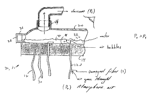
(dg'14~ Referring to Figures 1 to 7, a module 10 has a plurality of hollow
fiber membranes 12 with their ends t6 sealed in a block of potting material
14. In
the Figures, the number of membranes 12 has been greatly reduced for clarity.
The ends 1B Df the membranes 12 are open at one face 1$ of the potting
material 14. tn the embodiment illustrated, the ends 1 t3 of the membranes 12
are
machined flush with the face 28 of the potting material although, in ether
CA 02484096 2004-10-07
_ 1J
embodiments, the ends 16 of the membranes may protrude from the face 18 of
the potting material 14.
[001~~ A translucent or transparent cover 20 farms a plenum 23 with ifie
potting material 'f~l. in fibs embodiment illustrated, the bottom edges afthe
cover
20 are sealed to the face 18 of the potting material 14, which is flat, by
give or
welding. However, in other embodiments, alternate constructions may be used.
For example, the patting material 14 may extend to, and adhere or be glued or
welded to, fibs inside of the wails of the cover 20. The cover 20 may also be
removably attached, for example by screwing through a gasketed flange into the
potting material '14.
[0'16] The cover 20 has a port 24 which allows fluid communication
between the outside of the plenum 22, and the inside of the plenum 22, and to
the ends 16 of the membranes 12. In the embodiment illustrated, the port 24 is
a
permeate port used, in nom7al operation of the module 10, to apply a suction
to
the membranes 12. The module 10 illustrated is ordinarily immersed in a tank
of
water or wastewater at ambient pressure, with the operating surfaces 3g of the
membranes 12 in contact with the water ar wastewater, and used to withdraw a
filtered water permeate. However, in other embodiments, the module l0 and port
24 may have other uses, for example the withdrawal of fluids created by
pressurizing a fluid against the operating surface 30 of the membrane 12 or
the
injection of a fluid into the membranes 12 to be permeated or filtered out
through
the separating surfaces 30 of the membranes 12. The module 14 may have a
similar header assembly 32, comprising a cover 20, potting material 14 and
open
ends 1 B of the membranes 12, at the opposed ends of the membranes 12, or the
opposed ends of the membranes may be sealed but free, sealed in small,
movable groups, sealed into another block of potting material, or otherwise
arranged. Where the module 10 has membranes 12, each with a pair of open
ends 16 in opposed header assernbiies 32, both header assemblies 32 need to
be treated as disGUSSed below fio repair the mt~dule 10. The cover 20
illustrated
CA 02484096 2004-10-07
also has an access opening 26 with a selectively removable plug 28 aith~ough
in
other embodiments the port 24 may be used to perform the functions of the
access opening 26, or a temporary opening may be made, or example by drilling
a hale through the cover 20 and later sealing the hole when required.
X017] In Figure 1, the module 10 has been found to contain a damaged
fiber 12d by an integrity test on the module 10. The damaged fiber may, for
example, he broken or have a hole of unacceptable size. However, the location
of the damaged fiber 12d is not yet known. The module 10 is removed from its
tank and is head with the separating surfaces 30 of the fibers 12 exposed to a
~ 0 gas, far example air at ambient pressure. A layer of liquid 34, for
example water,
is poured into the plenum 22, for example through the port 24. The liquid 34
covers the ends 16 of the membranes 12, for example to a depth of about 1 cm.
[OO~fBa In Figure 2, a vacuum is applied to the part 24, at a pressure
sufficient to draw gas, in an amount suf)'icient to create a bubble, through a
defect requiring repair. Gas pulled through the damaged membrane 12d forms
bubbles 36 in the liquid 34. Observation of the bubbles through the
transparent or
translucent cover 20 allows the end 16d of the damaged membrane 12d to be
identified, for example by tracing the line of bubbles 36 back to the end 18d
of
the damaged fiber 12d yr observing which end 16 the bubbles 36 emerge from.
Qptionally, the end 16d of the damaged membrane 12d may be marked to aid in
later re-location, for example by placing a mark on the outside surface of the
cover 20 directly over the end 16d of the damaged membrane 12d. Altematefy, a
laser pointer or other light emitting device may be held outside of the cover
~0 so
that it illuminates the end 16d of the damaged membrane 12d.
[0019] In Figure 3, the vacuurn source is closed or disconnected and the
plug 28 removed from the Qpening 26. The liquid 34 is also removed from the
plenum 22. This may be done, for example, by draining though the opening 26 or
port 24, by sucking the liquid 34 into the membranes 't2 by applying a vacuum
to
their other ends, or by applying a pressurized gas to the port 24.
Alternatively,
CA 02484096 2004-10-07
-6-
the liquid 34 may be removed by leaving the opening 28 open while applying a
vacuum to the port 24 until the liquid 34 is evaporated ar carried away.
(00201 In Figure 4, a tool 40 is optionally inserted though the opening 26 to
prepare the surface of the end 1fid of the damaged fiber. The tool 4l), and
its
use, may vary according the specific sealing method that will be used. For
example, the tool ~.0 may be a vacuum ar blower wand used to further dry the
end 16d of the damaged membrane 12d. Alternately, the foal 40 may have a
moving head and be used to smooth or roughen a portion of the face 18 of the
potting material 14 or the end 16d of the damaged membrane 12d. Further
alternatively, the tool 40 may be a tube used to disperse one or more chemical
substances used to pre-treat the area to be sealed.
(0021] In Figure 5, the end 16d of the damaged membrane 12d is sealed.
A second tool 42 is inserted iota the plenum 22, far eacample through the
opening
2~, artd used to dispense a sealing material 44 onto, or into, the end 1Cd of
the
damaged membrane 12d. The sealing material 44 may be, far example, a resin,
silicone or other substance- '
X0022] In Figure ~, the sealing material 44 is optionally treated to decrease
its curing time. For example, an energy source 46 may be used from outside of
the cover 20 to send energy to the sealing material. The energy may be in the
farm of electromagnetic waves ar radiation such as light, infrared or
ultraviolet
radiation, or microwaves.
10023] In Figure 7, the access plug 28 has been replaced. The module 10
has been repaired. The integrity of the repair may be tested by repeating an
integrity test on the module 10. Alternately, the steps described in relation
to
Figures 1 and 2 may be repeated.
(0024.] Figure 8 shows a second header assembly 50. The second header
assembly 50 has a block of trotting material 14 and membranes 12 as before,
but
a second cover 52 has one ar more ports 24, but na special access openings for
CA 02484096 2004-10-07
..'
use only in locating or sealing damaged membranes 92. A third tool 54, or
other
tools, used with this second header assembly 20 are E,sent, curved, flexible
or
otherwise adapted to allow use through a port 24.
(0025 Figure 9 shows a second method of repairing a module 10. The
second method is shown as used with the second header assembly 50 of Figure
8, although it may also be used with other header assemblies. In the second
method, the energy source 46 is used to provide energy at sufficient intensity
to
melt the end 16d of the damaged fiber 12d closed, optionally after vaporizing
any
remaining liquid from the end 16a of the damaged membrane 12a.
1f1 ~Od26, Figures 90 to 12 show further alternate covers. In Figure 10, a
third
cover 60 has an elongated shape for use with an elongated or rectangular block
of potting material. Two ports 24, one in each half of the third cover G0, are
used
to provide better access through the ports 24 to the ends of the membranes. In
Figures 11 and 12, fourth and fifth covers 82, 64 are made in the shape of a
solid
of rotation for use with a cylindrical block of potting material 12. A single
port 24
is placed on the axis of rotation to provide better access to membranes
located
around the edges of the bundle of membranes. The fourth cover B2 is a portion
of a sphere while the fifth cover 64 is a cone. The height of the fifth cover
04 is
made large to facilitate use of straight tools through the port 24. In any of
the
covets 20, 52, 60, 62, 64, additional ports 24 or openings 2B may be provided
as
desired to improve access to the membrane ends, or temporary openings may
be made, for example by drilling holes through a wall of the cover 20, 52, 60,
62,
g~., to facilitate locating or repair procedures, and closing the temporary
holes, for
example by welding or gluing a plug into the temporary hole, before the module
'10 is returned to service.
[0027] Figure 13 shows a second method of locating a damaged
membrane. The second method is like the frrst except that the pressure
differential is applied by exposing the separating surface 30 of the membranes
12 to a pressurized gas such as air. Ta do this, the second header assembly 50
CA 02484096 2004-10-07
_$_
is sealed to a pressure vessel 70 containing the module 10_ Pressurized air is
provided to the pressure vessel 70 through a fitting 72. The pressure vessel
70
may be a part made particularly for use in a locating or repair procedure or
may
be all ar part of a shell used with the module in normal operafion. The port
24
may be exposed to air at ambient pressure. The method is shown with a module
20 having a second header assembly 50 at one end and closed fibers an the
other end, but may also be used with other modules.
[0028] Figure 1-0~ shows a third header assemf~ly 8fJ having a sixth cover
82. The sixth cover 82 is removable and replaceable against the potting
material
14. The sixth cover 82 is removably attached to the potting material 14 by
means
csf screws 84 screwed through a flange 86 of the sixth cover $2 and a gasket
88
between the flange 86 and potting material 94. The sixth cover 82 may be used
in normal operation of the module 10 or rnay be used only for the locating ar
repair procedure. In the latter case, the sixth cover $2 is replaced with a
different
cover when the module 90 is used in service. In this way, the design of the
sixth
cover 82 can be tailored far the locating or repair procedure while a separate
operating cover has a design tailored for the normal use of the membrane.
Optionally, the sixth cover 82 may be disposable.
[0028] The embodiments described above glue examples of the invention
but do not limit the scope of the invention and the invention may be practiced
with alternate apparatus elements or with alternate method steps. The
invention
may also be applied to devices of similar geometry, for example shell and tube
heat exchangers.
2s
~.x ~,.,.,, , " .. a w.. . ,mv";.~-tn . x ,.mmu;.» , wu . ~ w »r..,... .,...
_."_ . ,.__..._ " """" . ",.,,, <,a~,__.,.. ._ ._.__.....