Language selection

Search

Patent 2484672 Summary

Third-party information liability

Some of the information on this Web page has been provided by external sources. The Government of Canada is not responsible for the accuracy, reliability or currency of the information supplied by external sources. Users wishing to rely upon this information should consult directly with the source of the information. Content provided by external sources is not subject to official languages, privacy and accessibility requirements.

Claims and Abstract availability

Any discrepancies in the text and image of the Claims and Abstract are due to differing posting times. Text of the Claims and Abstract are posted:

  • At the time the application is open to public inspection;
  • At the time of issue of the patent (grant).
(12) Patent Application: (11) CA 2484672
(54) English Title: HOSE CLAMP
(54) French Title: BRIDE DE SERRAGE DE TUYAU SOUPLE
Status: Deemed Abandoned and Beyond the Period of Reinstatement - Pending Response to Notice of Disregarded Communication
Bibliographic Data
(51) International Patent Classification (IPC):
  • F16L 33/08 (2006.01)
(72) Inventors :
  • CHEN, DIAN-TAI (Taiwan, Province of China)
(73) Owners :
  • DIAN-TAI CHEN
(71) Applicants :
  • DIAN-TAI CHEN (Taiwan, Province of China)
(74) Agent: ROBIC AGENCE PI S.E.C./ROBIC IP AGENCY LP
(74) Associate agent:
(45) Issued:
(22) Filed Date: 2004-10-13
(41) Open to Public Inspection: 2006-04-13
Examination requested: 2006-10-20
Availability of licence: N/A
Dedicated to the Public: N/A
(25) Language of filing: English

Patent Cooperation Treaty (PCT): No

(30) Application Priority Data: None

Abstracts

English Abstract


A hose clamp includes a binding belt, which has a flat
head, a protruded portion adjacent to the flat head, a locating
hole formed in the protruded portion, a through hole cut through
the flat head, two bottom welding flanges at two sides of the
through hole, and two bottom stop blocks in front of the through
hole, and a screw holder attached to the top surface of the flat
head to hold a screw for joining the ends of the binding belt and
having two mounting plates respectively clamped on the bottom
surface of the flat head and stopped between the stop blocks and
the protruded portion and respectively welded to the welding
flanges by spot welding, the mounting plates each having a
positioning rod respectively engaged into the locating hole
in the protruded portion.


Claims

Note: Claims are shown in the official language in which they were submitted.

What the invention claimed is:
1. A hose clamp comprising:
a binding belt, said binding belt having a flat head, said
flat head having a top surface and a bottom surface, a protruded
portion adjacent to said flat head, a locating hole formed in said
protruded portion, a through hole cut through said flat head, two
welding flanges protruded from the bottom surface of said flat
head at two opposite lateral sides of said through hole, and a
plurality of stop blocks protruded from the bottom surface of
said flat head in front of said through hole; and
a screw holder fastened to said flat head of said binding
belt to hold a screw for joining the ends of said binding belt,
said screw holder comprising two mounting plates
respectively clamped on the bottom surface of said flat head and
stopped between said stop blocks and said protruded portion and
respectively welded to said welding flanges by spot welding,
said mounting plates each having a positioning rod respectively
engaged into said locating hole in said protruded portion.
2. The hose clamp as claimed in claim 1, wherein said
stop blocks are connected to one another in a line, forming a
transverse stop rib.
3. The hose clamp as claimed in claim 1, wherein said
8

mounting plates of said screw holder each have a welding flange
respectively welded to the flat bottom surface of said flat head
by spot welding.
9

Description

Note: Descriptions are shown in the official language in which they were submitted.


CA 02484672 2004-10-13
HOSE CL.AViP
BACKGROUND OF THE INVEIVTTION
1. Field of the Invention:
The present invention relates to a hose clamp for
fastening a hose to a pipe and more particularly, to a
high-strength hose clamp, which is durable in use.
2. Description of the Related Art:
FIGS. lA and 113 show a hose clamp according to the
prior art. According to this design, the hose clamp comprises a
binding belt 11, and a screw holder 15 holding a screw 10. The
binding belt 11 has a through hole 14 in the flat head thereof,
two side notches 13 at two opposite Lateral sides of the flat head,
and four stop flanges 12 at two ends of each of the side notches
13. The screw holder 15 has two mounting plates 16 respectively
fastened to the side notches 13 and stopped between the stop
flanges 12 and locating rods 17 respectively extended from the
mounting plates 16 at two sides and inserted through the thro~~gh
hole 14 from the back side toward the front side and then
respectively clamped on the front surface of the flat head of the
binding belt 11 in four corners around the through hole 14. This
design of hose clamp is still not satisfactory in function because
of the following drawbacks:
1

CA 02484672 2004-10-13
1. When the user rotating the scretv 10 to fasten up the
hose clamp, the torsional force produced from the rotary motion
of the screw 10 may cause the Locating rods 17 to deform and to
disengage from the flat head of the binding belt 11 (see the
imaginary line shown in FIG. 1C).
2. When rotating the screw 10 to fasten up the hose
clamp, the torsional force thus produced may cause the
mounting plates I6 to deform and to disengage from the side
notches 13 of the flat Dead of the binding belt 11.
SIT&IlVIARY OF T'FI~ INVENTION
The present invention has been accomplished under the
circumstances in view. It is the main object of the present
invention to provide hose clamp, which has a high strength and
is durable in use.
To achieve this and other objects of the present
invention, the hose clamp comprises a binding belt, the binding
belt having a flat head, the flat head having a top surface and a
bottom surface, a protruded portion adjacent to the t7at head, a
locating hole formed in the protruded portion, a through hole cut
through the flat head, two welding flanges protruded from the
bottom surface of the flat head at t~.vo opposite lateral sides of
the through hole, and a plurality of stop blocks protruded from
2

CA 02484672 2004-10-13
the bottom surface of the flat head in front of the through hole;
and a screw holder fastened to the flat head of the binding belt
to hold a screw for joining the ends of the binding belt, the
screw holder comprising two mounting plates respectively
clamped on the bottom surface of the flat head and stopped
between the stop blocks and the protruded portion and
respectively welded to the welding flanges by spot welding, the
mounting plates each having a positioning rod respectively
engaged into the Locating hole in the protruded. portion.
la BRIEF DESCRIP TION OF THE DRAW'IN~S
FIG. lA is an exploded view of a hose clamp according
to the prior art.
FIG. 1B is an assembly vierw in an enlarged scale of the
hose clamp according to the prior art.
FIG. 1 C is a schematic sectional view shaving a
breaking status of the hose clamp according to the prior art.
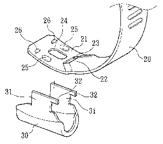
FIG. 2A is an exploded view of a hose clamp according
to the present invention.
FIG. 2I3 is an assembly view of the hose clamp
according to the present invention.
FIG. 3 is a schematic sectional view showing the
fastening operation of the hose clamp according to the present
3

CA 02484672 2004-10-13
invention.
FIG. 4 shows an alternate form of the hose clamp
accarding to the present invention (the screw holder not shown).
FIG. 5 shows another alternate form of the hose clamp
according to the present invention (the screw holder not shown).
FIG. b is an exploded view of still another alternate
form of the hose clamp according to the present invention.
FIG. 7 is a perspective view of still another alternate
form of the hose clamp according to the present invention.
FIG. 8 is a perspective view of still another alternate
form of the hose clamp according to the present invention.
DETAILED DESCRIPTION OF THE PREFERRED EIViBODIMENT
Referring to FIGS. 2A, 2B, and 3, a hose clamp in
accordance with one embodiment of the present invention is
shown comprised of a binding belt 20 and a screw holder 30
mounted with a screw 10.
The bindiaig belt 20 has a flat head 21, a protruded
portion 22 adjacent to the flat head 21, a locating hole 23
formed in the protruded portion 22, a through hole 24 cut
through the top and bottom surfaces of the flat head 21, two
welding flanges 25 protruded from the bottom surface of the flat
head 21 at two opposite lateral sides of the through hole 24, and

CA 02484672 2004-10-13
two stop blocks 26 protruded from the bottom surface of the flat
head 21 in front of the through hole 24.
The screw holder 30 comprises t~vo mounting plates 31
symmetrically disposed at two sides. Each mounting plate 31
~ has a positioning rod 32.
During installation, the screw holder 30 is attached to
the top surface of the flat head 21 of the binding belt 20, and
then the mounting plates 31 are respectively bent inwards and
clamped on the bottom surface of the flat head 21 of the binding
belt 20 and stopped between the stop blocks 2b and the
protruded portion 22, keeping the positioning rods 32 engaged
into the locating hole 23, and then mounting plates 31 are
fixedly fastened to the welding flanges 2~ by spot welding. H.
Because the mounting plates 31 of the screw holder 30
are stopped between the stop blocks 26 and the protruded
portion 22 and because the positioning rods 32 of the mounting
plates 31 are respectively engaged into the locating hole 23 of
the binding belt 20, rotating the screw 10 to fasten up the
binding belt 20 does not cause the screw holder 30 to break or to
disconnect from the flat head 21. Further, because the mounting
plates 31 are respectively welded to the welding flanges 25, the
screw holder 30 is maintained firmly secu~°ed to the flat head 21
5

CA 02484672 2004-10-13
of the binding belt 20.
The hose clamp may be variously embodied. According
to the embodiment shown in FIG. 4, there are three stop blocks
26 protruded from the bottom surface of the flat head 21 and
transversely aligned in a line in front of the through hole 24.
According to the embodiment shown in FIG. 5, a transverse stop
rib 27 is provided at the flat head 21 to substitute for the
aforesaid stop blocks 26. According to the embodiment shown in
FIG. 6, the two mounting plates 31 of the screw holder 30 each
have a welding flange 33 for welding to the flat bottom surface
of the flat head 21 of the binding belt 20. According to the
embodiment shown in FIG. 7, the binding belt 20 has a series of
teeth 28 arranged around the outer (top) sur face thereof for
engagement with the screw 10. According to the embodiment
shown in FIG. $, the binding belt 20 has a first series of teeth 28
arranged around the outer (top) surface thereof for engagement
with the screw 10 and a second series of teeth 29 arranged
around the inner (bottom) surface thereof for engaging the
peripheral wall of the hose to be affixed.
A prototype of hose clamp has been constructed with the
features of FIGS. 2--8. The hose clamp functions smoothly to
provide all the features discussed earlier.
6

CA 02484672 2004-10-13
Although particular embodiments of the invention have
been described in detail for purposes of illustration, various
modifications and enhancements may be made without departing
from the spirit and scope of the invention. Accordingly, the
invention is not to be limited eYCept as by the appended claims.

Representative Drawing
A single figure which represents the drawing illustrating the invention.
Administrative Status

2024-08-01:As part of the Next Generation Patents (NGP) transition, the Canadian Patents Database (CPD) now contains a more detailed Event History, which replicates the Event Log of our new back-office solution.

Please note that "Inactive:" events refers to events no longer in use in our new back-office solution.

For a clearer understanding of the status of the application/patent presented on this page, the site Disclaimer , as well as the definitions for Patent , Event History , Maintenance Fee  and Payment History  should be consulted.

Event History

Description Date
Application Not Reinstated by Deadline 2009-10-13
Time Limit for Reversal Expired 2009-10-13
Inactive: Abandoned - No reply to s.30(2) Rules requisition 2008-10-28
Deemed Abandoned - Failure to Respond to Maintenance Fee Notice 2008-10-14
Inactive: S.30(2) Rules - Examiner requisition 2008-04-28
Letter Sent 2006-11-10
All Requirements for Examination Determined Compliant 2006-10-20
Request for Examination Received 2006-10-20
Request for Examination Requirements Determined Compliant 2006-10-20
Application Published (Open to Public Inspection) 2006-04-13
Inactive: Cover page published 2006-04-12
Inactive: First IPC assigned 2005-01-28
Application Received - Regular National 2004-12-08
Filing Requirements Determined Compliant 2004-12-08
Inactive: Filing certificate - No RFE (English) 2004-12-08
Small Entity Declaration Determined Compliant 2004-10-13

Abandonment History

Abandonment Date Reason Reinstatement Date
2008-10-14

Maintenance Fee

The last payment was received on 2007-09-11

Note : If the full payment has not been received on or before the date indicated, a further fee may be required which may be one of the following

  • the reinstatement fee;
  • the late payment fee; or
  • additional fee to reverse deemed expiry.

Please refer to the CIPO Patent Fees web page to see all current fee amounts.

Fee History

Fee Type Anniversary Year Due Date Paid Date
Application fee - small 2004-10-13
MF (application, 2nd anniv.) - small 02 2006-10-13 2006-09-22
Request for examination - small 2006-10-20
MF (application, 3rd anniv.) - small 03 2007-10-15 2007-09-11
Owners on Record

Note: Records showing the ownership history in alphabetical order.

Current Owners on Record
DIAN-TAI CHEN
Past Owners on Record
None
Past Owners that do not appear in the "Owners on Record" listing will appear in other documentation within the application.
Documents

To view selected files, please enter reCAPTCHA code :


To view images, click a link in the Document Description column. To download the documents, select one or more checkboxes in the first column and then click the "Download Selected in PDF format (Zip Archive)" or the "Download Selected as Single PDF" button.

List of published and non-published patent-specific documents on the CPD .

If you have any difficulty accessing content, you can call the Client Service Centre at 1-866-997-1936 or send them an e-mail at CIPO Client Service Centre.


Document
Description 
Date
(yyyy-mm-dd) 
Number of pages   Size of Image (KB) 
Abstract 2004-10-13 1 25
Description 2004-10-13 7 237
Drawings 2004-10-13 8 150
Claims 2004-10-13 2 44
Representative drawing 2006-03-16 1 11
Cover Page 2006-03-30 1 39
Filing Certificate (English) 2004-12-08 1 158
Reminder of maintenance fee due 2006-06-14 1 110
Acknowledgement of Request for Examination 2006-11-10 1 178
Courtesy - Abandonment Letter (Maintenance Fee) 2008-12-09 1 174
Courtesy - Abandonment Letter (R30(2)) 2009-02-03 1 166
Fees 2006-09-22 1 33
Fees 2007-09-11 1 43