Note: Descriptions are shown in the official language in which they were submitted.
CA 02484725 2004-11-03
WO 03/096707 PCT/IB03/01755
HSDPA CQI, ACK, NACK Power Offset
Known In Node B and in SRNC
Background of the Invention
As an enhancement to the release99/release4 (re199/rel4) downlink shared
channel
(DSCH) concept in the third generation partnership project (3GPP) shown in
Fig. 1(a) it has
been agreed to add a so-called High Speed Downlink Packet Access (HSDPA)
concept as a
part of the 3GPP rel5 universal terrestrial radio access network (UTRAN)
architecture as shown
in Fig. 1(b). In Fig. 1(a) the DSCH is transmitted on a downlink Physical
Downlink Shared
CHannel (PDSCH) 10. In principle, the new HSDPA concept of Fig. 1(b) is an
enhancement,
because the leading idea in 3GPP has been to make HSDPA as an evolution from
the shared
channel concept not as a revolution. Therefore the defined solutions should
resemble as much
as possible the solutions which have already been defined for the shared
channels. The basic
idea behind the HSDPA is to offer a shared high speed channel with a higher
data rate and a
quick retransmission mechanism (i.e. with HARQ (= Hybrid Automatic Repeat
Request)) from
Node B. As can be seen by comparing Fig. 1(b) to Fig. 1(a), the Node B is
given more
intelligence for the purpose of handling retransmissions and scheduling
functions, thus reducing
the round trip delay between the mobile device and the RNC formerly handling
retransmissions
in Fig. 1(a). This makes retransmission combining feasible in the mobile
device. In place of the
variable spreading factor and fast power control used for the DSCH of Fig.
1(a), the HS-DSCH
of Fig. 1(b) uses adaptive modulation and coding (AMC) in addition to the
HARQ. A much
smaller transmission time interval (TTI) of two milliseconds is also used
instead of the 10 or 20
milliseconds of the DSCH. Also, the media access control (MAC) is located in
the node B
instead of the RNC. The AMC part of HSDPA utilizes adaptation of code rate,
the modulation
scheme, the number of multi-codes employed, as well as the transmit power per
code. Even
though many parameters are defined in the Radio Network Subsystem Application
Part
(RNSAP; see 3GPP TS25.423 v5Ø0) and Node B Application Part (NBAP; see 3GPP
TS25.433 v5Ø0) to support HSDPA, the HSDPA discussion is on-going in 3GPP
and many
useful parameters are being added.
The user equipment is able to send a channel quality indicator (CQI) on the
uplink HS-
DPCCH (high speed dedicated physical control channel). It indicates the
selected transport
format resource combination (TFRC) and multi-code number currently supported
by the UE.
Fig. 1(c) shows further details of the proposed UTRAN side overall MAC
architecture
including the new MAC-hs. MAC-hs provides the essential functionalities to
support HSDPA.
MAC-hs has the scheduling function as well as HARQ.
1
CONFIRMATION COPY
CA 02484725 2004-11-03
WO 03/096707 PCT/IB03/01755
Currently in 3GPP, the SRNC is supposed to send the CQI Power Offset, ACK
Power
Offset and NACK Power Offset to the UE via RRC layer messages. Fig. 2 shows a
radio
interface protocol architecture for HSDPA. The Power Offsets will be defined
as relative to the
DPCCH pilot bit. Then the UE will use these Power Offsets as follows:
When an uplink HS-DPCCH is active, the relative power offset HS-DPCCH between
the
DPCCH and the HS-DPCCH for each HS-DPCCH slot shall be set as follows:
For HS-DPCCH slots carrying HARQ Acknowledgement:
AHS-DPCCH = AACK if the corresponding HARQ Acknowledgement is equal to 1
AHS-DPCCH = ANACK if the corresponding HARQ Acknowledgement is equal to 0
For HS-DPCCH slots carrying CQI:
AHS-DPCCH = ACQI
The values for AACK, ANACK and ACQI are set by higher layers (RRC message).
The quantization
of the power offset can be found in 3GPP TS 25.213 at Table 1A for instance.
Disclosure of Invention
But in the current 3GPP specification, there is no means to deliver these
Power Offsets
to Node B. Referring to Figs. 1(c) and Fig. 2, the prior art Node B of Fig.
1(a) did not have the
MAC-hs or complementary HS-DSCH FP layers. If Node B were to know the CQI
Power offset,
which is an object of the present invention, the Node B receiver could utilize
this value for
scaling the CQI signal. Scaling the CQI signal is related to the signal level
setting, and is used
typically in a digital base band implementation, to avoid overflow (i.e.
signalling saturation) or
underflow (i.e. quantization noise). In ASIC and DSP SW implementations, word
length
constraints are applied and signals must be scaled accordingly to match with
the processing
word lengths. If the power offsets for multiple signals are not known by the
Node B, as is the
case now, signal levels would have to be detected or alternatively in a worst
case the Node B
receiver would have to be made available for a possible maximum range of each
signal.
Especially in this case, both fading on the radio path and adaptation POs
extend the required
range. Signaling to Node B removes the later proportion for the required
range. Therefore, if
Node B knows the CQI Power Offset then it simplifies receiver implementation
(i.e. when
measuring DPCCH power level, CQI power level can be calculated and Node B can
adjust
gains in the different parts of receiver in a simple manner).
If Node B knows the ACK Power Offset and the NACK Power Offset, Node B can
utilize
these values to detect the ACK/NACK signal. For the ACK and NACK detection,
the Node B
2
CA 02484725 2004-11-03
WO 03/096707 PCT/IB03/01755
receiver must also detect the 3rd state, DTX (no signal). This requires
setting signal detection
thresholds. This detection will be more accurate when it is set based on
signaled POs than
when it is set based on measured offsets.
Since ACK/NACK is a level based detection, if Node B already knows the POs of
ACK/NACK, it can detect the signal easily.
If Node B knows the CQI Power Offset it can calculate the CQI power with DPCCH
power, Node B doesn't need to measure the offset individually. It can make
Node B receiver
implementation easier.
If Power Offsets are not given by signalling, Node B is required to measure
these Power
Offsets individually. This is similar with beta parameters, which are given
for DPCCH and for
DPDCH, to indicate power offset between those two dedicated physical channels.
Of course, in
these schemes, the Node B receiver must still detect the DPCCH level, which is
the reference
for all the Power Offsets, but it doesn't need to detect other signal levels
(CQI's, ACKs &
NACKs) individually for all multiple signals and this reduces Node B work
significantly.
Furthermore it is anticipated that giving Power Offsets to the Node B will
make the
standard further future-proof when supporting some interference cancelling
methods.
Currently, no description can be found from 3GPP specifications or technical
reports
about this problem and how to solve it. Therefore, there is no prior art
recognition of the
problem and consequently no solution either. Without knowing the CQI Power
Offset, ACK
Power Offset and NACK Power Offset, the Node B receiver has to search the
signal for whole
possible ranges.
This invention introduces CQI Power Offset, ACK Power Offset and NACK Power
Offset
on RNSAP and NBAP signalling or HS-DSCH FP.
Since the object is for both the UE and Node B to know the same values, there
are two
possibilities during the RL setup phase:
(1) SRNC decides the Power Offsets and includes them in the RL SETUP REQUEST
message. SRNC also sends the same information to the UE with a proper RRC
message.
(2) Node B decides the Power Offsets and includes them in the RL SETUP
RESPONSE
message. And the SRNC sends the same Power Offsets to the UE with the proper
RRC
message.
3
CA 02484725 2009-12-15
And, there are 3 possibilities to change the POs.
1) SRNC decides to change the Power Offsets and include them in the RL
RECONFIGURATION PREPARE message. SRNC also sends the same information to UE
with
proper RRC message.
2) SRNC decides to change the Power Offsets and include them in the RADIO
INTERFACE
PARAMETER UPDATE control frame (it should be noted that the name of the
control frame
can be different than that). SRNC also sends the same information to UE with
proper RRC
message.
3) Node B decides to change the Power Offsets. In this case there is no
existing mechanism for
Node B to initiate changing the Power Offsets during the connection and there
may be a need
to define a new procedure. Alternatively, it could be done in such a way that
the SRNC initiates
Power Offsets change procedure (e.g. SHO case) by sending an RL
RECONFIGURATION
PREPARE message with HO indication. Then Node B decides new Power Offsets and
sends
them back in an RL RECONFIGURATION READY message. SRNC also sends the same
information to UE with proper RRC message. The RL RECONFIGURATION PREPARE and
RL RECONFIGURATION message formats already exist and can be adapted to the
purposes
of the invention.
Once Node B has the CQI Power Offset, ACK Power Offset and NACK Power Offset,
it
will apply CQI Power Offset for CQI slot scaling and ACK Power Offset and NACK
Power Offset
for ACK and NACK slot detection.
Accordingly, in one aspect there is provided a method for use by a serving
radio network
controller of a radio access network comprising:
sending a radio link setup request signal to a base station of said radio
access network,
said radio link setup request signal comprising one or more information
elements indicative of
one or more corresponding power offsets, said power offsets including at least
one of a channel
quality indicator power offset, an acknowledge power offset and a negative
acknowledge power
offset;
receiving a radio link setup response signal from said base station indicative
of receipt
of said radio link setup request signal by said base station; and
sending a radio resource controller message signal to a user equipment device
indicative of said one or more power offsets;
4
CA 02484725 2009-12-15
wherein said one or more power offsets are for use by said user equipment in
sending
feedback information over a radio interface to said base station at power
levels adjusted
according to said one or more power offsets.
According to another aspect there is provided an apparatus, comprising a
signal
receiving unit, a signal sending unit and a control unit, wherein the
apparatus is configured to:
send a radio link setup request signal to a base station of a radio access
network
directly or via a drift radio network controller associated with said base
station, said radio link
setup request signal comprising one or more information elements indicative of
one or more
corresponding power offsets, said power offsets including at least one of a
channel quality
indicator power offset, an acknowledge power offset and a negative acknowledge
power offset;
receive a radio link setup response signal from said base station directly or
via said drift
radio network controller indicative of receipt of said radio link setup
request signal by said base
station; and
send a radio resource controller message signal to a user equipment device
indicative
of said one or more power offsets;
wherein said user equipment device uses said one or more power offsets in
sending
feedback information over a radio interface to said base station at power
levels adjusted
according to said one or more power offsets.
According to yet another aspect there is provided a computer readable storage
medium
having program codes stored thereon for execution by a serving network
controller of a radio
access network, said program codes comprising:
instructions for sending a radio link setup request signal to a base station
of said radio
access network directly or via a drift radio network controller associated
with said base station,
said radio link setup request signal comprising one or more information
elements indicative of
one or more corresponding power offsets, said power offsets including at least
one of a channel
quality indicator power offset, an acknowledge power offset and a negative
acknowledge power
offset;
instructions for receiving a radio link setup response signal from said base
station
directly or via said drift radio network controller indicative of receipt of
said radio link setup
request signal by said base station; and
instructions for sending a radio resource controller message signal to a user
equipment
device indicative of said one or more power offsets;
wherein said one or more power offsets are for use by a user equipment device
in
sending feedback information over a radio interface to said base station at
power levels
adjusted according to said one or more power offsets.
4a
CA 02484725 2009-12-15
According to still yet another aspect there is provided a system comprising:
a serving radio network controller (S-RNC) for sending a radio link (RL) setup
request
signal from a radio network subsystem application part (RNSAP) thereof to a
RNSAP of a drift
radio network controller (D-RNC) using radio network layer signaling
procedures specified for
use between two radio network controllers, said RL setup request signal
including one or more
information elements indicative of power offsets (PO) including at least one
of a channel quality
indicator (CQI) PO, an acknowledge (ACK) PO and a negative acknowledge (NACK)
PO, said
D-RNC having a Node B application part (NBAP) for sending said radio link
setup request
signal to an NBAP of a Node B associated with said D-RNC for future use by
said Node B,
wherein said NBAP of said Node B is for sending a radio link setup response
signal to said
NBAP of said D-RNC indicative of receipt of said RL setup request signal by
said NBAP of said
Node B, wherein said RNSAP of said D-RNC is for sending said radio link setup
response
signal to said RNSAP of said S-RNC via said RNSAP of said D-RNC, and wherein
said S-RNC
is for sending a radio resource controller (RRC) message signal to a user
equipment (UE)
indicative of said one or more information elements.
These and other objects, features and advantages of the present invention will
become
more apparent in light of the following detailed description of a best mode
embodiment thereof,
as illustrated in the accompanying drawing.
Brief Description of the Drawings
Figure 1: UTRAN side overall MAC architecture showing the defined HSDPA
network
architecture in 3GPP. The figure shows a new MAC -hs entity, which is
connected, to the MAC
-c/sh through lub -interface. The used transport channel under MAC -hs are HS-
DSCH, which
corresponds in re199 shared channel concept DSCH transport channel.
4b
CA 02484725 2004-11-03
WO 03/096707 PCT/IB03/01755
Figure 2: Radio Interface Protocol Architecture of HSDPA. The defined protocol
stack defines
the HS-DSCH FP protocol to provide the HSDPA FP data frames through lub -
interface.
Figure 3: UTRAN side MAC architecture / MAC-c/sh details.
Figure 4: UTRAN side MAC architecture / MAC-hs details.
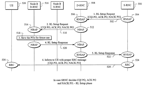
Figure 5: In case SRNC sets CQI PO, ACK PO and NACK PO - RL Setup Phase.
Figure 6: In case Node B sets CQI PO, ACK PO and NACK PO - RL Setup Phase.
Figure 7a: In case SRNC decides to change the values of CQI PO, ACK PO and
NACK PO -
Using Control Plane protocol.
Figure 7b: In case SRNC decides to change the values of CQI PO, ACK PO and
NACK PO -
Using User Plane protocol.
Figure 8: In case SRNC decides to change the values of CQI PO, ACK PO and NACK
PO -
Using User Plane protocol - Frame structure.
Figure 9: In case Node B sets CQI PO, ACK PO and NACK PO - RL Setup Phase.
Best Mode for Carrying Out the Invention
Abbreviations
CRNC Control RNC (network element)
DPCCH Dedicated Physical Control Channel
DPCH Dedicated Physical Channel
DPDCH Dedicated Physical Data Channel
DSCH Downlink Shared Channel (transport channel)
FDD Frequency Division Duplex (operation mode)
FP Frame Protocol
HARQ Hybrid Automatic Repeat Request (function)
HO Hand Over
HS-DSCH High Speed - Dedicated Shared Channel (transport channel)
HS-PDSCH Physical Downlink Shared Channel
HS-SCCH Shared Control Channel for HS-DSCH
5
CA 02484725 2004-11-03
WO 03/096707 PCT/IB03/01755
HS-SICH Shared Info Channel for HS-DSCH
HSDPA High Speed Downlink Packet Access (concept)
MAC Medium Access Controller (protocol layer)
MCS Modulation and Coding Scheme
NBAP Node B Application Part
PDSCH Physical Downlink Shared Channel
PO Power Offset
RL Radio Link
RLC Radio Link Control (protocol layer)
1o RNC Radio Resource Controller (network element)
RNSAP Radio Network Subsystem Application Part
UE User Equipment (user device)
The power of the HS-DPCCH is set as a power offset (PO). These POs can be
defined
as POs of the DPCH. In detail, they can be defined as PO relative to DPCCH
pilot field. In
addition, to guarantee full cell-coverage a CQI repetition scheme can be used
whereby periodic
CQI's are sent in the uplink HS-DPCCH. Node B then sends user data on the HS-
DSCH
according to its own schedule to the users using time and/or code multiplexing
to better utilize
the available resources also considering UE capability. The Node B prenotifies
the UEs of the
transport format and resource combination (TFRC), the multi-code set, as well
as the HARQ
process control on the HS-SCCH two slots in advance of the HS-DSCH. After
receiving the
user data on HS-DSCH, the UE sends a CQI and/or ACK/NACK on the uplink HS-
DPCCH as a
feedback signal after a verification time of several slots. Considering the
foregoing, especially
the new HSDPA-RRM entities (HRQ, packet scheduling, link adaptation) in the
Node B, it will
be advantageous for the Node B to know the CQI power offset and the POs of
ACK/NACK as
givens determined either by itself or by the RNSAP/NBAP of the RNC.
As described in the Fig 5 and 6, during the RL Setup phase, there are 2
possibilities for
accomplishing this end from the outset:
(1) SRNC decides CQI PO, ACK PO and NACK PO
(2) Node B decides CQI PO, ACK PO and NACK PO
In the first case, since SRNC knows the SHO status of UE, based on the SHO
situation
it can decide the CQI PO, ACK PO and NACK PO. In this case SRNC will assign
these POs in
the RL Setup Request message during RL setup phase. SRNC will send the same
values to
UE using proper RRC message.
6
CA 02484725 2004-11-03
WO 03/096707 PCT/IB03/01755
The signalling flow for this example is described in Fig 5. In Fig. 5, a
serving radio
network controller (S-RNC) 500 provides an RL SETUP REQUEST message as a
signal on a
line 502 from a radio network subsystem application part (RNSAP) 504 to an
RNSAP 506 of a
drift radio network controller (D-RNC) 508. The D-RNC 508 processes the RL
SETUP
REQUEST signal received on the line 502 and provides said RL SETUP REQUEST
signal on a
line 510 from a Node B application part (NBAP) 512 of the D-RNC 508 to an NBAP
514 of a
Node B 516 under D-RNC 508. The RL SETUP REQUEST signal on the line 502 and on
the
line 510 may include one or more power offset information elements including a
CQI PO, an
ACK PO and a NACK PO. In that case, the Node B 516 saves the POs for future
use as
indicated in a step 518. The step 518 should therefore be viewed as also
representative of a
memory within said Node B. The NBAP of Node B 516 then sends an RL setup
response
message as a signal on a line 520 to the NBAP of the D-RNC 508. The D-RNC 508
then sends
the RL setup response signal on a line 522 from its RNSAP to the RNSAP of the
S-RNC 500.
A radio resource control (RRC) 524 of the S-RNC 500 then informs a UE 526 with
a proper
RRC message signal on a line 528 which is received in the corresponding RRC
530 of the UE
526. The RRC message includes the CQI PO, the ACK PO and the NACK PO for use
by the
UE in sending CQI's, NACK's and ACK's on the HS-DPCCH uplink to the Node B.
Since the
Node B has saved the POs for future use, and it therefore already knows these
POs, it can use
them in interpreting the CQI, ACK and NACK information sent by the UE to the
Node B without
having to be in the dark, so to speak. As can be seen by the illustration of
Fig. 1(b) as
compared to that of Fig. 1(a), the process is made more efficient. It should
be realized that a
given S-RNC 500 may be in direct communication with an associated Node B, and
therefore
the steps shown in Fig. 5 could be carried out without using the D-RNC 508 as
an intermediary.
For the sake of completeness, however, Fig. 5 shows the possibility of using a
D-RNC
intermediate between the S-RNC and the Node B. Consequently, the RL setup
request signal
on the line 502 can be sent directly to the Node B 516 or via the D-RNC 508.
Likewise, the
signalling descriptions shown in Figs. 6, 7A, 7B and 9 should also be
understood in this way for
signals both in the direction from the S-RNC toward the Node B and in the
reverse direction.
In the second case, referring now to Fig. 6, since Node B knows HSDPA related
resource status and can be considered to have better knowledge of HSDPA, it
can decide the
CQI PO, ACK PO and NACK PO. But in this case Node B doesn't know whether it is
in an HO
situation or not. Therefore the SRNC has to give the HO Indication. As
described in Fig 6, in an
RL Setup Request message is sent by an S-RNC 600 by its RNSAP on a line 602 to
an
RNSAP 604 of a D-RNC 606 and includes an HO Indication. An NBAP 608 of the D-
RNC 606
provides an RL SETUP REQUEST message as a signal with the HO indication on a
line 610 to
an NBAP 612 of a Node B 614 of the D-RNC 606. The Node B 614 then decides the
POs
based on the HO indication and its own measurements and consequent decisions
and saves
7
CA 02484725 2004-11-03
WO 03/096707 PCT/IB03/01755
the POs for future use as indicated in a step 616. After that, the NBAP of the
Node B 614
sends an RL setup response message as a signal with the decided PO information
elements on
a line 618 to the NBAP of the D-RNC 606. The RNSAP of the D-RNC 606 then sends
the RL
setup response message on a signal line 620 to the RNSAP of the S-RNC 600. An
RRC 622 of
the S-RNC 600 then informs a UE 624 by means of a proper RRC primitive message
on a
signal line 626 including the CQI, ACK and NACK PO information elements to an
RRC 628 of
the UE 624. The UE then uses the PO information in setting the powers of the
various CQI,
ACK or NACK slots of its HS-DPCCH.
And if SRNC is the node to change the Power Offset values then it can use the
Synchronised RL Reconfiguration Procedure as described in Fig 7a to change the
POs, once
established. One example of this case can be the soft handover (SHO)
situation. In an RL
Reconfiguration Preparation message on a signal line 7a2, an RNSAP 7a4 of an
SRNC 7a6
can include new CQI PO or/and ACK PO or/and NACK PO or/and and a Node B 7a8
shall
apply these new values. And if Node B can use the values it will reply with an
RL
Reconfiguration Ready primitive message on a line 7a10 as a positive ACK. If
Node B cannot
use the values, then it will reply with RL Reconfiguration Failure message. In
case of SRNC
determination of Power Offsets, to change the POs, it is also possible to use
a user plane
Frame Protocol (FP) as described in Fig 7b. In this case, in the FP, a proper
control frame
should be defined or used. For instance like in the DCH FP, it is desirable to
define a Radio
Interface Parameter Update control frame and deliver these POs in this control
frame as shown
for instance on a line 7b10 from an HS-DSCH FP 7b12 of an S-RNC 7b14. An
example of such
a frame structure is depicted in Fig 8. The name of the control frame or the
order of the fields
can of course be different than that shown in Fig. 8. The important point here
is these Power
Offsets can be delivered by a UP control frame. In Fig 8, the flag points to
whether the
corresponding Power Offsets are valid data or not. In the example, Flag bit 1
indicates CQI PO,
bit2 ACK PO and bit3 NACK PO. If the flag is 1 then the corresponding PO value
is valid.
Compared to using the control plane, using the user plane is a rather lighter
solution. But in the
case of using the user plane, the delivery cannot be guaranteed (No response
message).
Therefore repeatedly sending the same control frame multiple times can be an
option. This can
make Node B receive the POs with higher probability.
If Node B is the node to change these POs and Node B is the node to initiate a
PO
change procedure, a new message is needed to be defined from Node B to SRNC so
that the
new message can include new POs. After receiving new POs, SRNC will forward
these new
POs to the UE. But if Node B is the node to change these POs and SRNC is the
node to
initiate the PO change procedure (e.g. SRNC changes the POs during SHO),
Synchronised RL
Reconfiguration Procedure can be used as describe in Fig 9. SRNC 900 sends the
RL
8
CA 02484725 2004-11-03
WO 03/096707 PCT/IB03/01755
Reconfiguration Prepare message from an RNSAP 902 on a line 904 to an RNSAP
906 of a D-
RNC 908 with HO Indicator, and then an NBAP 910 of a Node B 912 receives the
HO indication
on a line 914 from an NBAP 916 of the D-RNC 908 and decides 918 new POs and
sends them
back from the NBAP 910 to DRNC in an RL Reconfiguration Ready message 920.
After
receiving same from the D-RNC RNSAP, the SRNC forward those POs to the UE on a
line 930
using a proper RRC message. And this whole procedure can be implemented in FP
(Frame
Protocol). I.e., SRNC can give the HO indication by control frame in FP and
Node B will provide
CQI PO, ACK PO and NACK PO in a control frame in FP. And also Node B can
provide CQI
PO, ACK PO and NACK PO with this control frame without SRNC's request.
When HSDPA is implemented CQI Power Offset, ACK Power Offset and NACK Power
Offset signalling will be implemented as defined in the specification. During
HSDPA service,
always UE and Node B shall have same Power Offset (CQI, ACK and NACK) values.
Therefore
whenever HSDPA is implemented, this feature should be implemented.
Although the invention has been shown and described with respect to a best
mode
embodiment thereof, it should be understood by those skilled in the art that
the foregoing and
various other changes, omissions and additions in the form and detail thereof
may be made
therein without departing from the spirit and scope of the invention.
9