Note: Descriptions are shown in the official language in which they were submitted.
CA 02484908 2004-10-15
"COLLAPSIBLE PORTABLE WELDING STAND"
FIELD OF THE INVENTION
The field of present invention relates generally to providing a
collapsible portable stand and, more particularly, to providing a stand for
supporting
pipe and other metal items during welding operations.
BACKGROUND OF THE INVENTION
To prepare for the welding and fabrication of metal pipe, welders
typically support a particular section of pipe, that is next in line to be
welded, with a
V-top bracket mounted on a traditional tripod stand. At other times, a bracket
with
pipe-rolling means is supported by a tripod stand.
However, the tripod stands have a tendency to tip over or collapse
under the weight of a pipe section. An advantage therefore exists for a stand
for
safely supporting metal pipe sections, or other objects, while still being
collapsible
and portable.
DETAILED DESCRIPTION OF THE PREFERRED EMBODIMENTS
Reference is to be had to the Figures in which identical reference
numbers identify similar components.
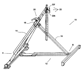
Referring to FIGS. 1 - 15 and 25, one embodiment of a stand 10 of the
present invention is shown. The stand 10 generally includes a base 12, a first
leg
CA 02484908 2004-10-15
element 14, a second leg element 16, a pivot mount 18, and a pivot mount
locking
means 20. The base 12 supports first leg element 14 and second leg element 16
at
opposing ends of the base 12. Leg elements 14, 16 are pivotally connected to
the
base 12 at pivot point A and pivot point B respectively, as shown in the FIGS.
Pivot
mount 18 is slidably connected to the first leg element 14 so as to enable
pivot
mount 18 to slidably move along substantially all the length of first leg
element 14.
Pivot mount 18 is also pivotally connected to the second leg element 16 at the
end
of said leg element 16 opposite to pivot point B as shown in the FIGS. Locking
means 20 allow for the pivot mount 18 to be locked against the first leg
element 14
at substantially any portion along leg element 14's length. Preferably, the
components of the stand 10 are made of steel or any other suitable material of
high
strength and rigidity.
The stand 10 further comprises support means 22 mounted on the
first leg element 14. In this embodiment support means 22 comprises a
telescoping
support 22a, a second pivot mount 22b and a V-top bracket 22c. The V-top
bracket
22c is mounted on the telescoping support 22a at one end. The telescoping
support 22a is pivotally connected to the first leg element 14 near the end of
the first
leg element 14 opposite to pivot point A, via the second pivot mount 22b, as
shown
in the FIGS. In this embodiment, the telescoping support 22a comprises
telescope
sleeve 22d, telescope bar 22e and telescope locking means 22f. The telescope
sleeve 22d is mounted to the second pivot mount 22b as shown in the FIGS. The
telescope bar 22e is slidedly mounted within the telescope sleeve 22d.
Telescope
2
CA 02484908 2004-10-15
locking means 22f functions to hold telescope bar 22e at certain slideable
positions
relative to telescope sleeve 22d. Additionally, in this embodiment second leg
element 16 has a telescope opening 16a therethrough to allow the telescoping
bar
22e to pass through the second leg element 16 as may be desired.
In another embodiment (not shown), support means 22 comprises a
V-top bracket directly mounted or connected to the first leg element 14 at an
appropriate angle. In yet another embodiment (also not shown), support means
22
comprises a bracket with pipe rolling means mounted directly on the first leg
element 14.
The stand 10 may be displaced from a storage position (see FIGS. 3
and 4) to a support position (see FIGS. 1, 2 and 6). The displacement of the
stand
10 from a storage position to a support position is accomplished as follows.
The
first leg element 14 is pivoted upward relative to the base 12 as can be seen
in FIG.
5. The pivot mount 18 is slidably moved from the bottom end of the first leg
element
14 towards the top end of the first !eg element 14 (see FIG. 6). The locking
means
are engaged so as to secure the sliding pivot mount 18 at the top end of the
first
leg element (see FIGS. 7 and 8).
Preferably the stand 10 further comprises securing means 24. In a
preferred embodiment, securing means 24 comprises pin 24a depending from the
telescoping sleeve 22d and a recess or opening 24b in second leg element 16.
The
3
CA 02484908 2004-10-15
pin 24a depends from the telescope sleeve 22d at an appropriate angle so as to
engage the recess 24b when the stand 10 is in the support position as more
clearly
shown in FIGS. 2 and 14.
FIGS. 17 to 24 illustrate a second embodiment of the stand 10. This
embodiment of the stand 10 is similar to the first embodiment as discussed
above
with the following noteable differences. The second leg element 16 of this
embodiment of the stand 10 does not have a telescope opening therethrough.
Also,
the pivot mount 22b is attached at a different position on the first leg
element 14
when compared to the first embodiment shown in FIGS. 1 -15 and 25. Operation
of
the stand 10 of the second embodiment is similar to the operation of the stand
10 of
the first embodiment as discussed above.
The stand 10 of the present invention, in its various embodiments, is
more stable than traditional tripod stands and can be built in any size as may
be
desired (whereas tripod stands traditionally are limited to a certain upper
size before
they become too awkward and unwieldy to use efficiently). The stand 10 may
also
be used for purposes other than welding.
4
