Note: Descriptions are shown in the official language in which they were submitted.
CA 02485008 2004-11-03
WO 03/097549 PCT/US03/08651
1
TITLE
Reflective, Solar Control Coated Glass Article
BACKGROUND OF THE INVENTION
The invention relates to coated glass and, in
particular, to visible light reflecting, solar control
coated glass articles.
Coatings on architectural glass are commonly utilized
to provide specific energy absorption and light
transmittance properties. Additionally, coatings provide
desired reflective or spectral properties that are
aesthetically pleasing. The coated articles are often
used singularly or in combination with other coated
articles to form a glazing or window unit.
~ Coated glass articles are typically produced "on-
line" 'by continuously coating a glass substrate while it
is being manufactured in a process known in the art as the
"float glass process." Additionally, coated glass
articles are produced "off-line" through a sputtering
process. The former process involves casting glass onto a
molten tin bath which is suitably enclosed, thereafter
transferring the glass, after it is sufficiently cooled,
to lift out rolls which are aligned with the bath, and
finally cooling the glass as it advances across the rolls,
initially through a lehr and thereafter. while exposed to
the ambient atmosphere. A non-oxidizing atmosphere is
maintained in the float portion of the process, while the
CA 02485008 2004-11-03
WO 03/097549 PCT/US03/08651
2
glass is in contact with the molten tin bath, to prevent
oxidation of tin. An oxidizing atmosphere is maintained
in the lehr. In general, the coatings are applied onto
the glass substrate in the float bath of. the float bath
process. However, coatings may also be applied onto the
substrate in the lehr.
The attributes of the resulting coated glass
substrate are dependent upon the specific coatings applied
during the float glass process or an off-line sputtering
process. The coating compositions and thicknesses impart
energy absorption and light transmittance properties
within the coated article while also affecting the
spectral properties. Desired attributes may be obtainable
by adjusting the compositions or thicknesses of the
coating layer or layers. However, adjustments to enhance
a specific property can adversely impact other
transmittance or spectral properties of the coated glass
article. Obtaining desired spectral properties is often
difficult when trying to combine specific energy
absorption and light transmittance properties in a coated
glass article.
There is an increasing demand for solar control
glasses, especially high performance solar control glasses
that exhibit a neutral color in both reflection and
transmission. "High performance" solar control glasses
means glasses that transmit a significantly higher
CA 02485008 2004-11-03
WO 03/097549 PCT/US03/08651
3
percentage of incident light than of total incident
radiation energy (total solar heat).
It would be advantageous to provide a coated stack
for a glass article that is itself color neutral, so that
. for the coated glass article, the reflected color from the
film side is neutral, and transmitted color remains
substantially unchanged from that of the selected base
glass. A visible light reflecting, solar control glazing
with a low emittance, and a low solar heat gain
coefficient, would significantly improve energy costs in
buildings and homes while providing a desirable neutral
color for, at least, film side reflection. The low
emittance characteristic of the glazing would minimize any
indirect heat gain from absorption.
SUMMARY OF THE INVENTION
According to the invention there is provided a
visible light reflecting, solar control article comprising
a glass substrate, a first coating deposited over the
glass substrate and a second coating deposited over the
first coating. The first coating is comprised of a doped
metal oxide, and in an especially preferred embodiment is
comprised of fluorine doped tin oxide. The first coating
provides the low emissivity of the coated glass article.
The second coating is comprised of a transparent
metal oxide having a refractive index greater than the
refractive index of the first coating. The addition of
CA 02485008 2004-11-03
WO 03/097549 PCT/US03/08651
4
the second coating increases the visible light reflectance
of the coated glass article, so that the resulting coated
glass article has a film side reflectance Rf > 15~ and an
emissivity less_than or equal to about 0.3.
Preferably, the coated glass article includes an
iridescence-suppressing interlayer deposited between the
glass substrate and the first coating of the doped metal
oxide. The coatings are such as to provide a neutral
color in transmittance and reflectance when applied to a
clear glass substrate.
DESCRIPTION OF THE DRAWINGS
The advantages of the invention will become readily
apparent to those skilled in the art from the following
detailed description of a preferred embodiment when
considered in the light of the accompanying drawings, in
which:
Figure 1 is a sectional view through a coated glass
article in accordance with one embodiment of the
invention.
Figure 2 is a sectional view through a coated glass
article in accordance with a second preferred embodiment
of the invention.
Figure 3 is sectional view through a double glazing
unit incorporating a coated glass article as illustrated
in Figure 1.
CA 02485008 2004-11-03
WO 03/097549 PCT/US03/08651
DETAILED DESCRIPTION OF THE PREFERRED EMBODIMENTS
Referring to Figure 1, a visible light reflecting,
solar control coated glass article 1 comprises a glass
substrate 11 and a multi-layer coating 12 including a low
5 emissivity layer 14 and a reflecting layer 13.
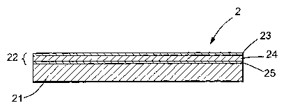
The embodiment shown in Figure 2 is similar to the
embodiment of Figure 1, with a coated glass article 2
comprising a glass substrate 21 and a multi-layer coating
22. However, coating 22 differs from coating 12 in that
it comprises, in addition to low emissivity layer 24 and
reflecting layer 23, an iridescence suppressing underlayer
25 as further discussed hereinafter.
Figure 3 illustrates the coated glass pane 1 of
Figure 1 assembled in parallel spaced apart relationship
with a second pane of glazing material 31, typically of
clear float glass, the panes being spaced apart and sealed
together by spacing and sealing system 32, to form double
glazing unit 3 having airspace 33. The coating 12 faces
the airspace 33 of the unit, with the coating facing
towards the interior of the glazed space (usually, but not
necessarily, a building). The second pane of glazing
material 31 may, in certain preferred embodiments, be
provided with a low emissivity layer (not shown) facing
towards the airspace 33.
The glass substrates suitable for use in preparing
the coated glass article according to the present
invention may include any of the conventional glass
CA 02485008 2004-11-03
WO 03/097549 PCT/US03/08651
6
compositions known in the art as useful for the
preparation of architectural glazings. The preferred
substrate is a tinted float glass ribbon wherein the
coatings of the present invention are applied in the
heated zone of the float glass process. Additionally,
clear glass substrates may be suitable for applying the
multilayered stack of the invention. However, the tinted
glass substrates are especially preferred for their impact
on the spectral and energy transmittance properties of the
coated glass article.
The low emissivity layer is a layer of a metal
compound, normally a metal oxide (as other low emissivity
compounds such as metal nitrides and metal silicides tend
to have lower light transmissions), and a transparent
i5 semiconductor, for example, a doped indium, tin or zinc
oxide. Preferred materials include tin doped indium oxide
and fluorine doped tin oxide, with fluorine doped tin
oxide being especially preferred. The low emissivity
0
layer will normally have a thickness in the range 1000 A
0
to 6000 A (as use of a thicker layer is likely to result
in an unnecessary reduction in light transmission without
sufficient reduction in emissivity to compensate),
0 0
especially a thickness in the range 2000 A to 5000 A. The
low emissivity layer provides an emissivity of less than
0.3 (the numerical values of emissivity referred to in
this description and the accompanying claims are values of
CA 02485008 2004-11-03
WO 03/097549 PCT/US03/08651
7
hemispherical emissivity (Eh)), although it is preferred
to use a low emissivity layer which provides an emissivity
of 0.2 or less.
The reflecting layer is deposited over the low
emissivity layer in the coated glass article of the
invention. The reflecting layer has-a refractive index in
the visible spectrum that is greater .than the refractive
index of the low emissivity layer. The refractive index
of the reflecting layer will generally be greater than or
equal to about 2Ø The reflecting layer is normally a
layer of a transparent metal oxide, such as oxides of
titanium, zirconium or chromium. An oxide of titanium is
an especially preferred material for forming the
reflecting layer of the coated glass article.
Titanium oxide coatings formed by atmospheric
pressure chemical vapor deposition, such as those
described in U.S. Patent No. 6,238,738, which is
incorporated herein by reference, are known to be
photocatalytic and hydrophilic. Thus, use of the coating
stack of the invention on an exterior-facing surface of a
glazing will result in so-called "self-cleaning"
properties. Of course, use of the coating stack of the
invention on the exterior-facing surface of an insulated
glass unit will negatively impact the solar control
properties relative to use of the same coating stack on an
unexposed surface of a pane of an insulating glass unit.
CA 02485008 2004-11-03
WO 03/097549 PCT/US03/08651
8
Use of thin films, as in the present invention, may
result in the appearance of interference colors and
iridescence. To avoid, or at least alleviate, undesirable
color resulting from interference effects, a color
suppressing underlayer (which may itself be a combination
of sub-layers) may be applied to the glass prior to
deposition of the low emissivity and reflecting layers.
Iridescence-suppressing coatings are conventionally known
within the art. For example, U.S. Patent Nos. 4,187,336;
4,419,386; and 4,206,252, herein incorporated by
reference, describe coating techniques suitable for
suppressing interference colors. The interlayer of the
present invention may comprise a single iridescence-
suppressing coating, a two-layer coating, or a gradient
coating. Thus, according to a preferred aspect of the
invention, an iridescence suppressing layer or layers is
incorporated under the coating comprising a low emissivity
layer and reflecting layer.
The low emissivity layer and reflecting layer of the
present invention may be deposited by known techniques,
for example, by sputtering, including reactive sputtering,
or by chemical vapor deposition. Indeed, it is an
important advantage of the invention that both the above
layers are susceptible to deposition by chemical vapor
deposition techniques providing for the possibility of
applying the coating to the hot ribbon of glass during the
glass production process. Methods of depositing metal
CA 02485008 2004-11-03
WO 03/097549 PCT/US03/08651
9
oxides by chemical vapor deposition are described, for
example, in U.S. Patent Nos. 5,698,262; 5,773,086 and
6,238,738, each of which is incorporated by reference
herein.
The invention is illustrated but not limited by the
following Examples. In the Examples, as in the remainder
of the description and claims, Tvis represents the visible
light transmission measured using Illuminant C on a
Perkin-Elmer Lambda 19 spectrophotometer. The total solar
heat transmissions (Tsol) stated are determined by
weighting with a solar spectral irradiance function (ASTM
E891-87) that represents the direct normal radiation
incident on a surface (air mass 1.5). The Rg and Rf are
the total visible light reflectances measured from the
glass and film sides respectively. These reflectances
were measured using a Colorsphere spectrophotometer
available from BYK Gardner Scientific. SHGC is the solar
heat gain coefficient and SC is the shading coefficient.
The winter time U values and summer time U values are
denoted as Uwin and Usum respectively. The color. of light
transmitted and reflected from the film side of the coated
glass articles is measured according to the CIELAB color
scale coordinates of a* and b*.
Examples 1-3
The mufti-layer coating stacks of Examples 1-3 were
deposited by chemical vapor deposition on a clear float
CA 02485008 2004-11-03
WO 03/097549 PCT/US03/08651
glass ribbon during the float glass~production process.
The glass was 3-3.2 mm in thickness. An iridescence-
suppressing interlayer was first deposited onto the
surface of the glass substrate in the heated zone of a
5 float glass production process. The iridescence-
suppressing layer .included a tin oxide coating deposited
on and adhered to the glass substrate. The tin oxide was
applied by chemical vapor deposition in the heated zone of
the float glass process by introducing dimethyl tin
10 dichloride in an oxidizing atmosphere over the surface of
the substrate. A silicon dioxide coating was then applied
onto the surface of the tin oxide coating by reacting
silane, in the presence of oxygen and ethylene, near the
surface of the substrate in the heated zone of the float
process.
A fluorine doped tin oxide coating was deposited onto
the surface of the silicon dioxide coating. The fluorine
doped tin oxide coating was deposited by chemical vapor
deposition in the heated zone of the float glass process
by introducing dimethyl tin dichloride, water and hydrogen
fluoride in an oxidizing atmosphere over the surface of
the substrate.
A titanium dioxide coating was deposited onto the
surface of the fluorine doped tin oxide coating. The
titanium dioxide coating was also deposited by chemical
vapor deposition in the heated zone of the float glass
process by introducing titanium tetrachloride and an
CA 02485008 2004-11-03
WO 03/097549 PCT/US03/08651
11
organic oxygen source over the surface of the substrate,
as described in U.S. Patent No. 6,238,738.
The layer thicknesses in Angstroms, measured
optically, and the properties of the resulting coated
glass articles are shown below in Table 1. In each case,
the haze was less than 1.0~. .
Table 1
Ex. Sn02 Si02 SnO2:F Ti02. Tvis Rf Eh T T b* Rf Rf
a* a* b*
1 269 227 2325 320 71.0122.8 .21 0.97 5.09 -5.5 -4.6
2 280 182 2064 502 66.9627.2 .25 1.63 3.18 -6.1 -1.0
3 291 210 2738 302 76.1817.0 .18 -1.925.78 2.0 -7.9
0
Examples 4 -15
A coated glass article was produced in accordance
with Examples 1-3 having the following layer thicknesses:
a o 0 0
271 A Sn02, 172 A Si02, 2100 A SnO2:F, and 300 A Ti02.
The Eh of the sample was measured to be 0.22. Properties
were then calculated for this coating stack on various
glass substrates, clear and a variety of tints, having a
thickness of ~/ inch. These examples are numbered 4-9 and
are shown below in Table 2.
Properties were also calculated for the same coated
glass articles of Examples 4-9 as utilized as the outboard
light in an insulated glass unit with the coating stack
facing the interior of the structure. A '/~ inch thick
CA 02485008 2004-11-03
WO 03/097549 PCT/US03/08651
12
clear glass sheet was used as the inboard light of the
insulated glass unit and positioned at 1/z inch from the
coated article. These examples are numbered 10-15 and are
shown below in Table 3.
Table 2 lMonolithicl
ExampleTvis Tsol Rg Rf SHGC SC Uwin Usum
4 66.9 57.2 23.9 26.0 0.61 0.71 0.76 0.68
5 41.8 25.3 13.1 22.6 0.38 0.44 0.77 0.75
6 56.9 35.8 20.1 22.3 0.45 0.53 0.76 0.73
7 41.1 36.7 ~ 12.3 22.6 0.47 0.54 0.76 0.73
8 50.1 24.5 16.7 23.0 0.37 0.43 0.77 0.75
9 ~ 33.4 30.7 9.8 22.3 ~ 0.42 0.49 0.76 0.75
~ ~ ~ ~
Table 3 (IG Unit)
ExampleTvis Tsol Rg Rf SHGC SC Uwin Usum
60.3 45.5 27.6 28.8 0.54 0.63 0.35. 0.38
11 37.6 21.1 14.6 26.1 0.30 0.34 0.35 0.40
12 51.2 29.5 22.8 26.6 0.38 0.44 0.34 0.39
13 36.9 29.1 13.7 26 0.38 0.45 0.35 0.39
14 45.0 20.7 18.8 26.3 0.29' 0.34 0.35 0.40
~ 30.0 24.4 10.~ 25.8 0.34 0.39 0.35 0.40
CA 02485008 2004-11-03
WO 03/097549 PCT/US03/08651
13
The glasses used in the above examples are all
commercially available from Pilkington North America, Inc.
of Toledo, Ohio. Examples 4 and 10 are on clear glass;
examples 5 and 11 are on a blue glass sold under the
trademark Arctic Bluetm; examples 6 and 12 are on blue-
green glass; examples 7 and 13 are on bronze glass;
examples 8 and 14 are on a green glass sold under the
trademark Evergreentm; and examples 9 and 15 are on grey
glass.
The coatings of the present invention offer important
advantages over the prior art. Being suitable for
production by pyrolytic methods (which have the added
benefit of lending themselves to application on-line) they
can be obtained in highly durable form, reducing the need
for special care in handling and processing and opening up
the possibility of using the coatings in free standing
glazing without the need to protect them within multiple
glazing units.
Moreover, excellent performance may be achieved, with
coated glass articles having an emissivity less than or
equal to about 0.3 and preferably less than .or equal to
about 0.2, and an Rf of 15% or more, preferably l8% or
more, and most preferably 20% or more. Tn~hen deposited on
a suitable tinted glass, the resulting coated glass
articles have an SHGC of 0.5 or less, preferably 0.45 or
less.
CA 02485008 2004-11-03
WO 03/097549 PCT/US03/08651
14
The preferred coated glasses of the present invention
are glasses wherein the coating is such as to exhibit
reflection (when viewed from the coated side) and
transmission (when applied to clear float glass) colors
such that (a*2 + b*2)~ is less than 12, especially less
than 10. In especially preferred embodiments, the
reflection and transmission colors are each such that
(a*2 + b*2) ~ is less than 7.
15
25