Note: Descriptions are shown in the official language in which they were submitted.
CA 02485049 2004-10-18
1
Title: THERMAL BALANCE TEMPERATURE CONTROL SYSTEM
BACKGROUND OF THE INVENTION
The present invention relates to a temperature control system and, more
particularly,
to a system which directly regulates the system output to balance such output
with
the sensible thermal load.
Heating, ventilating and air-conditioning (HVAC) systems are used to both heat
and
cool the air within an enclosure, e.g., a building or zone within such
building. An
HVAC system typically includes a heating unit, a cooling unit, a supply air
fan, a
supply duct for directing air into the enclosure, and a return duct for
removing air
from the enclosure. It will be appreciated by those skilled inn the art that
HVAC
systems are generally designed to operate in one of three modes: a heating
mode
to heat the enclosure, a cooling mode to cool the enclosure and a economizer
mode
to ventilate the enclosure. The economizer mode typically utilizes both an
outdoor
air damper and a return air damper, commonly referred to as an economizer,
that
can be selectively modulated opened to allow the return air to mix with fresh
outside
air.
There is typically a control system associated with an HVAC system, such
control
system including a thermostat (typically located within the enclosure) and
associated
hardware/software for controlling the components of the particular HVAC system
in
response to pre-programmed instructions. Typically, the control system allows
a
user to pre-select one of the three operating modes, as well as selecting a
desired
temperature for the enclosure. Thereafter, the control system activates either
the
heating or cooling portion of the HVAC system to maintain the pre-selected
temperature within the enclosure. Under certain conditions the economizer mode
may be able to maintain the enclosure at the pre-selected temperature.
CA 02485049 2004-10-18
2
When set in the cooling mode, the control system will provide cold air to the
enclosure when the temperature of the enclosure exceeds the pre-selected
temperature. The control system accomplishes this task by activating the
cooling
unit (or stage of a mufti-stage cooling unit) and the supply air fan. The
supply air fan
blows the air through the cooling unit and into the enclosure. As a result of
the cold
air entering the enclosure, the temperature in the enclosure is lowered. Once
the
temperature in the enclosure falls below the pre-selected temperature, the
thermostat in the enclosure provides a signal to the control system which
either turns
off the cooling unit, or turns off a stage of cooling (if part of a mufti-
stage unit).
Similarly, when set in the heating mode, the control system will provide hot
air to the
enclosure when the temperature of the enclosure falls below the pre-selected
temperature. The control system accomplishes this task by activating the
heating
unit (or stage of a mufti-stage heating unit) and the supply air fan. The
supply air fan
blows the air through the heating unit into the enclosure. As a result of the
hot air
entering the enclosure, the temperature in the enclosure is raised. Once the
temperature in the enclosure rises above the pre-selected temperature, the
thermostat in the enclosure provides a signal to the control unit which either
turns off
the heating unit, or turns off a stage of heating (as part of the mufti-stage
unit).
As mentioned, the economizer mode may be able to maintain the enclosure at the
pre-selected temperature under certain conditions. Particularly, during times
when
the outside air temperature is low (e.g., 5~° F), and the control
system needs to
provide cold air to the enclosure to cool such enclosure, the system can
utilize the
economizer mode to provide the desired cold air to the enclosure. In the
economizer
mode, the control system will selectively modulate open and close both an
outside
air damper and a return air damper to mix the cool outside air with the warmer
return
air. In this manner, the air being supplied to the enclosure is cooled to the
desired
temperature without the need for activating the cooling unit. Of course, if
the outside
air temperature is too high and/or too humid, the cooling unit will need to be
activated.
CA 02485049 2004-10-18
3
The above-described temperature control systems are typically designed to
allow
"time cycling" of the heatinglcooling components, which of course
limitlpreclude
these known systems from regulating the BTU output of the HVAC to balance such
output with the measured sensible thermal load.
More to the point, those skilled in the art will appreciate that "time
cycling" prevents a
system from operating in a "real time" mode, and often allows undesirable
temperature swings, as well as inefficient operation of the individual
components.
This inefficient operation can include the operation of excess cooling/heating
capacity (resulting in unneeded energy costs) and excess cycling of the
systems
components (resulting in the shortening of the life of the unit andlor an
increase in
maintenance of such unit). In fact, the prior art has generally believed that
real time
temperature control systems which attempt to directly regulate BTU output to
balance such output with the system load are inherently unstable, and will
produce
excessive and potentially damaging "short cycling" of the heatinglcooling
components.
Moreover, the prior art systems are generally inefficient because the supply
air is
often colder/hotter than necessary to satisfy the measured sensible thermal
load.
Finally, such systems are generally incapable of satisfying an unmet
cooling/heating
load.
There is therefore a need in the art for a dynamic real time temperature
control
system which directly regulates the BTU output of an HVAC package to balance
such output with the sensible thermal load being measured in the temperature-
regulated enclosure, thereby eliminatinglreducing undesirable temperature
swings in
the regulated environment, reducing excess cycling of components and
eliminating/reducing utilization of unneeded excess capacity.
SUMMARY OF THE INVENTION
The present invention, which addresses the needs of the prior art, relates to
a
method of controlling room temperature within a zone of a temperature control
system. The method generally includes the steps of defining a thermal demand
set
CA 02485049 2004-10-18
4
point temperature curve for the temperature control system, measuring a
sensible
thermal load within the zone, calculating a thermal demand set point
temperature
based upon the sensible thermal load, defining at least one load band for the
temperature control system corresponding to an equilibrium condition, and
operating
the temperature control system to maintain individual components of the system
in a
constant operating condition for as long as the system operates within the
load band.
The present invention further relates to a thermal balance temperature control
system for controlling room temperature within a predefined zone. The system
includes at least one air handling unit for providing supply air at a
preselected
temperature, the air handling unit includes at least one unit stage. The
system
further includes a supply duct for transporting supply air from the air
handling unit to
the predefined zone. Finally, the system includes at feast one controller for
controlling room temperature within the predefined zone. The controller
comprises
at least one processor circuit for measuring a sensible thermal load within
the zone
and for calculating a thermal demand set point temperature based upon the
sensible
thermal load in accordance with a predefined thermal demand set point
temperature
curve. The processor circuit operates the temperature control system to
maintain
the unit stage in an energized condition for as long as the system operates
within a
predefined load band corresponding to an equilibrium condition.
Finally, the present invention relates to a controller for controlling room
temperature
within a zone of a temperature control system. The controller includes at
least one
processor circuit for measuring a sensible thermal load within the zone and
for
calculating a thermal demand set point temperature based upon the sensible
thermal
load in accordance with a predefined thermal demand set point temperature
curve.
The processor circuit operates the temperature control system to maintain
individual
system components in a constant operating condition for as long as the system
operates within a predefined load band corresponding to an equilibrium
condition.
As a result, the present invention provides a dynamic real time temperature
Control
system which directly regulates the BTU output of an HVAC package to balance
such output with the sensible thermal load being measured in a temperature-
,CA 02485049 2004-10-18
regulated enclosure, thereby eliminatinglreducing undesirable temperature
swings in
the regulated environment, reducing excess cycling of components and
eliminatinglreducing utilization of unneeded excess capacit'~.
BRIEF DESCRIPTION OF THE DRAWINGS
5 Figure 1 is a schematical representation of a heating, ventilating and air
conditioning system including the thermal balance temperature control system
of the
present invention;
Figure 2 is a schematical representation of the components of an HVAC
package used in accordance with the present invention;
Figure 3 is a graphical representation of the thermal demand set point
temperature curve for the thermal balance temperature control system of the
present
invention;
Figure 4 is a graphical representation of a cooling load band curve for the
thermal balance temperature control system of the present invention;
Figure 5 is a graphical representation of an economizer load band curve
superimposed on the curve of figure 4; and
Figure 6 is a schematical representation of the controller used in accordance
with the present invention.
DETAILED DESCRIPTION OF THE INVENTION
As discussed more fully hereinbelow, the present invention is directed to a
method
and apparatus for controlling a temperature-regulated zone utilizing a thermal
balance temperature control system. The thermal balance control system is a
dynamic real time control system that constantly measures the sensible thermal
load
in the mentioned zone, and directly regulates the BTU output of the HVAC
package
to balance such output with the measured sensible thermal load, thus providing
a
state of system equilibrium. The system will continue to operate in this
equilibrium
CA 02485049 2004-10-18
6
state (without time cycling of any heatinglcooling components) until the
system
measures a change in the sensible thermal load within the mentioned zone.
The sensible thermal load is the amount of deviation (measured in degrees)
between
the set point temperature for the zone and the actual zone temperature. When
the
actual room temperature is above the set point temperature, the sensible
thermal
load is a cooling load, and the system must therefore reduce the supply air
temperature to balance the BTU output of the HVAC package with such load. If
the
actual room temperature is below the set point temperature, then the sensible
thermal load is a heating load, and it is necessary for the system to increase
the
supply air temperature to balance the BTU output with such load.
The thermal balance control system of the present invention utilizes the
formula:
Thermal Transfer Rate (BTUIHR) = Supply Air Volume (cubic feet per minute) x
1.08
x (Room Temperature-Supply Air Temperature). As will be appreciated from the
foregoing formula, the thermal transfer rate is equal to 0 when the room
temperature
is equal to the supply air temperature.
As discussed herein, the thermal balance control system of the present
invention
operates in a "load cycling" manner, in contrast to the "time cycling" manner
of
conventional units. It will be appreciated that available HVAC units which
operate in
an on/off function (e.g., direct expansion (DX) cooling, electric heat, etc.)
are typically
utilized in a time-cycled manner. Particularly, if the prior art system
requires supply
air at 55° and stage 1 of a DX cooling system only reduces the
temperature to 60°,
the second stage of such system will be cycled on and off to reduce the
temperature
of the supply air to below 55°. Every time a unit cycles on and off the
system can
experience wide and comfortable temperature swings. With respect to the
cycling on
and off of a DX cooling unit, condensation caught in a coil will evaporate
back into
the supply air when such unit is cycled off. This increase in humidity of the
supply air
can cause discomfort to the occupants in the building, and also decreases the
overall efficiency of the unit (in that the unit must again remove the vapor
from the air
when cycled back on). For example, the cycling of a stage of DX cooling on a
rainy
summer day may cause such an undesirable condition.
CA 02485049 2004-10-18
7
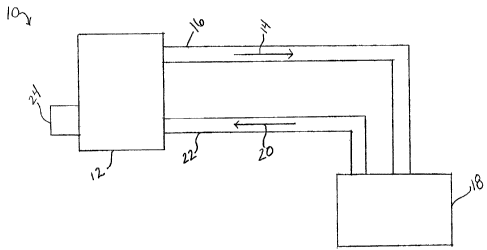
Referring to Figure 1, a thermal balance temperature control system 10 in
accordance with the present invention includes a heating, ventilating and air
conditioning (HVAC) package 12 for supplying cold or heated supply air 14 (as
well
as fresh outside air) into a supply air duct 16, which communicates with an
interior
enclosure, i.e., zone 18. Return air 20 is thereafiker removed from zone 18
via return
air duct 22. Temperature control system 10 also includes a thermal balance
controller 24, which is a dynamic real time controller that measures the
sensible
thermal load in zone 18, and regulates the output capacity of HVAC package 12
to
balance such output with this measured load.
As shown in Figure 2, HVAC package 12 includes a supply air fan 26 for moving
supply air into zone 18 and a return air fan 28 for removing return air from
zone 18.
HVAC package 12 further includes an economizer section 30, a heating unit 32,
a
cooling unit 34 and a supply air temperature sensor 36. Package 12 may also
include a filter 38, a low temperature alarm 40 and low limit temperature
sensor 42.
Economizer section 30 preferably includes an exhaust damper 44, an outside air
damper 46 and a return air damper 48. Return air damper' 48, together with
outside
air damper 46, control the percent mixture of return airlfresh air being fed
into supply
air duct 16. Those skilled in the art will understand that e~:haust damper 44,
outside
air damper 46 and return air damper 48 are preferably operated to meet at
least
some of the following goals: 1) to operate in economizer mode when conditions
permit; 2) to take maximum advantage of the temperature of the return air; and
3) to
mix sufficient fresh air into the supply air.
In one preferred embodiment, HVAC package 12 includes an economizer section, a
two-stage gas heating section, a three-stage direct expansion (iJX) cooling
unit, a
constant volume supply fan and a constant volume return air fan. One preferred
package is rated at 25 tons at 10,000 cubic feet per minute. This design
capacity is
based on approximately 400 cubic feet per minute per ton, and 5-6 air changes
per
hour. The operation sequence of HVAC package 12 preferably follows an ASHRAE
Cycle ll.
CA 02485049 2004-10-18
g
Thermal balance temperature control system 10 can be used in a constant volume
system or in a variable air volume (VAV) system. It will be recognized by
those
skilled in the art that a VAV system would utilize variable speed supply and
return
fans (in contrast to the constant speed fans used in a constant volume
system).
Unlike the constant volume system, the VAV system will typically include a
differential pressure gauge located in the supply air duct downstream from the
supply air fan.
Thermal balance temperature control system 10 may operate in either the
heating,
economizer or cooling mode, depending on the sensible thermal load measured
within zone 18. More particularly, the heating mode is preferably controlled
by
cycling (in sequence) the two gas valves to maintain a desired supply air
temperature. The heating mode is generally not initiated until outside air
damper 46
is at its minimum open setting. Preferably, morning warm-up will be
accomplished
with both outside air damper 46 and exhaust damper 44 fully closed, and return
damper 48 fully opened. The economizer cooling mode is preferably controlled
by
modulating exhaust damper 44, outside air damper 46 and return air damper 48
to
maintain the desired supply air temperature. The economizer cooling mode is
preferably limited by an outside air temperature sensor set at 60° that
reduces the
intake of fresh outside air (for ventilation) to a minimum value at
temperatures
exceeding 60°. Of course, this 60° setting is adjustable,
depending on system
criteria. Finally, the cooling mode is preferably controlled by cycling the
stages of
cooling in direct relation to the sensible thermal load measured within zone
18.
Because temperature control system 10 seeks to balance the BTU output of HVAC
package 12 with the sensible thermal load measured within zone 18, the stages
of
heating and cooling do not experience short cycling (i.e., excessive cycling
on and
cycling off of the individual stages). Rather, such stages remain activated
until such
time as the system measures a change in the sensible thermal load.
It will be appreciated by those skilled in the art that a multi-stage
heating/cooling unit
generally provides better overall efficiency. For example, in a multi-stage
cooling
unit having three stages, each stage providing approximately 33% of the total
cooling
capacity of the unit. When maximum cooling is required, all three stages can
be
CA 02485049 2004-10-18
9
activated. However, when maximum system output is not needed, one or more
stages can be deactivated, thus allowing the system to operate in a more
energy-
efficient mode. Similarly, each stage in a two-stage unit provides 50% of the
total
capacity of the unit, while each stage of a four-stage unit provides 25% of
the total
capacity. In ane embodiment, the relay differential of a stage of cooling is
made
greater then the temperature change which results from that stage being
energized
or deenergized. This prevents the cooling stage from short cycling due to the
action
of the discharge sensor. Preferably, the relays should be set up to provide
Vernier
controls.
It will be understood by those skilled in the art that resetting the
temperature of the
supply air in response to certain system measurements can improve the
performance and operation of the overall system. Although prior art systems
utilize
reset schedules, such schedules generally consist of a standard fixed ratio
which
does not directly correlate to the operating characteristics of the system and
does
nat allow the system to reach a state of equilibrium. In contrast, the thermal
demand
set point temperature curve for the system of the present invention (as shown
in
Figure 3) is established to directly correlate with the operating
characteristics of
HVAC package 12 and to allow the system to reach a state of equilibrium (i.e.,
the
BTU output is balanced with the measured sensible thermal load).
Referring now to Figure 3, the illustrated thermal demand set point
temperature
curve for HVAC package 12 includes a heating portion and a cooling portion.
For
example, if the particular heating unit is capable of providing a maximum
temperature rise of 50°, then the heating portion of the curve is drawn
to extend
between a minimum thermal demand set point Po (wherein 0 heat is required) and
a
maximum thermal demand set point P~ (wherein maximum heat, i.e., plus
50° F) is
. required. This maxirrium heat condition corresponds to a measured sensible
thermal
load of -2° F. The cooling portion of the curve is drawn in accordance
with the
particular cooling unit installed in the system. For example, if the system is
capable
of reducing the supply air temperature by a maximum of 45°, then the
curve is drawn
between a minimum thermal demand set point P° (wherein 0 cooling is
required) and
a maximum thermal demand set point P2 (wherein maximum cooling, i.e., minus
CA 02485049 2004-10-18
25°F,) is required. This maximum cooling condition corresponds to a
measured
sensible thermal load of +2°F.
The thermal demand set point temperature curve of Figure 3 is based upon a
temperature band of plus and minus 2°F. On a drop in space temperature
of 2°F,
5 the supply air temperature will be reset from set point temperature Pp to Po
plus 50°F.
On a rise in space temperature of 2°F, the supply air temperature will
be reset from
set point temperature Po to Po minus 25°F. This band can, of course, be
widened
(although widening the band may cause the temperature in zone 18 to move into
an
uncomfortable region), may be narrowed (which may increase the cost of
operating
10 such system) or may include integral control action far improved
responsiveness.
The method of the current system will now be described with respect to Figures
3
and 4. As described, Figure 3 is used to calculate the thermal demand set
point
temperature of the supply air during operation of the system. To begin, the
sensible
thermal load in zone 18 is measured. lf, for example, the room set point is
73°F and
the actual measured room temperature is 74°F, the deviation from set
point (i.e., the
sensible thermal load) is +1°. Referring to the thermal demand set
point temperature
curve of Figure 3, a +1 temperature deviation is within the cooling portion of
the
curve and corresponds to approximately -12.5° on the Y axis. The set
point Po of
Figure 3 corresponds to the set point temperature of zone 18. Thus, the
thermal
demand set point temperature for the supply air would be calculated to be
73° -
12.5°= 60.5°. This is the temperature at which the system is
balanced, i.e., providing
supply air at 60.5°F to zone 18 will maintain zone 18 in a state of
equilibrium at 74°F.
In certain applications, as described in commonly-owned co-pending U.S.
application
Serial No. 10/704,251 filed November 7, 2003, the disclosure of which is
incorporated herein by reference, the system can be designed to recognize this
unmet cooling load (i.e., the +1 °F in zone 18). Thereafter., the
system would
calculate and supply the additional cooling necessary to move the actual room
temperature towards the room set point.
Figure 4 illustrates the novel load band curve of the present invention, which
is
preferably a proportional curve having preselected parameters which correspond
to
CA 02485049 2004-10-18
11
the components of the system. The particular graph shown in Figure 4
represents a
plot for a multi-stage DX cooling system having three stages wherein the
maximum
cooling is approximately 20°. A 40% allowance (i.e., 8°) may be
designed into the
system such that the X axis extends from 0° to 28°. (20°
+ (40% of 20°)). The X axis
of the load band is 10° wide (i.e., it extends from 9° to
19°). It will be appreciated
that each stage of the three stage DX cooling system is capable of
approximately a
7° temperature drop. Again, a 40% allowance may be designed into the
system to
provide a total of approximately 10° (7° + (40% of 7) = 9.8,
vrhich is approximately
10°).
If the desired supply air temperature is calculated to be 60.5° (as
discussed
hereinabove), the set point S of the graph of Figure 4 will be set to
60.5°. The value
of this point wilt remain fixed until the system measures a change in the
sensible
thermal load in zone 18 and recalculates the thermal demand set point
temperature
from Figure 3. The actual supply air temperature (as measured by sensor 36) is
then plotted along the curve. With set point S set at 60.5° F, point S~
will correspond
to 55.5° F and point SZ will correspond to 65.5° F:
The first stage of cooling will be turned on, resulting in a 7° drop of
temperature. If
this is sufficient to bring the supply air temperature within the load band
which, in this
example, will extend from 55.5° to 65.5° (5° on either
side of the set point), then no
additional stages will be turned on. As long as the supply air temperature
remains
within this load band, the first stage of the compressor will remain on.
Unlike
conventional systems which would automatically begin time cycling this stage
of the
compressor, the system of the present invention will allow this stage of the
compressor to stay on as long as the supply air temperature remains within in
such
load band. In other words, the thermal balance control of the present
invention has
reached a state of system equilibrium, and may remain in this state until a
change in
the sensible thermal load is measured.
The portion of the curve of Figure 4 extending from point ;i~ to S2 is
referred to
herein as the load band. Once the supply air temperature moves outside of the
load
band, it moves into one of two integrating regions. For example, if two stages
of the
CA 02485049 2004-10-18
12
three stage compressor are on and the supply air temperature continues to
decrease
such that it moves down the curve into the lower integral region, an integral
factor
will increase the speed at which the supply air temperature imoves towards the
stage-off point. Once, the supply air temperature hits this point, the
particular stage
is turned off, thereby raising the supply air temperature and pushing such
supply air
temperature back towards the load band. Likewise, if the supply air
temperature
increases such that it moves up the curve into the upper integral region,
eventually
additional stages of cooling will be turned on. Again, integral action
decreases the
time necessary to reach the point where an additional stages of cooling is
turned on.
Thus, the system anticipates overcooling and undercooling through the integral
action portions of the control system.
More particularly, the system anticipates a change in the sensible thermal
load. If
the load is increasing (thus indicating the need for an extra atage of
cooling), the
thermal demand set point temperature will decrease (thus providing a lower set
point
to the cooling control module). The supply air temperature will now be higher
than
the thermal demand set point temperature, and will begin to move up the curve
into
the upper integral region. An integral factor will increase the speed at which
the
supply air temperature moves towards the stage-on point. I'f the sensible
thermal
load is decreasing, the reverse action will occur. As a result, the system
provides
load change anticipation.
Stated differently, the present invention anticipates gain in the wrong
direction, and
corrects this unwanted gain prior to the regulated enclosure experiencing an
uncomfortable temperature swing. It will be appreciated by those skilled in
the art
that although a conventional system would eventually compensate for the change
in
the temperature of the supply air, because of the inherent time delays and
time
constants associated with HVAC systems, the conventional system cannot respond
until "after the fact". In other words, the regulated enclosure: has already
undergone
the unwanted temperature swing before it begins to react to the temperature
swing
due the change in the temperature of the supply air.
CA 02485049 2004-10-18
13
Figure 5 illustrates an economizer load band curve superimposed on the cooling
load band curve of Figure 4. In this particular example the economizer load
band will
extend plus and minus 1.5° from set point S. Once the supply air
temperature has
increased 1.5° above set point S, the system will begin to modulate
open the outside
air damper. Similarly, once the supply air temperature decreases 1.5°
below set
point S, the system will begin to modulate closed the outside air damper.
While the
supply air temperature is within the economizer load band, the outside air
damper
will be maintained in a constant position.
Referring to Figure 6, the control system of the present invention, i.e.,
controller 24,
uses three individual control modules, namely a first control module 50 for
the
heating unit, a second control module 52 for the economizer unit and a third
control
module 54 for the cooling unit. The control system is desigined so that each
one of
the individual control modules operates its respective unit depending on
whether the
supply air temperature is above or below the thermal demand set point
temperature
calculated from Figure 3.
The system calculations and operations described hereinak~ove are preferably
performed by controller 24, and particularly by the individual control
modules. More
particularly, the controller and/or control modules preferabl,r include
hardwarelsoftware which is capable of performing the mentioned calculations,
and of
utilizing predefined thermal demand set point temperature and load band curves
to
control the operations of system 10 in accordance with the parameters
described
herein.
It should be noted that each control module receives two sE;ts of numbers.
Specifically, each module receives the thermal demand set point temperature TP
for
the supply air (from Figure 3), and the actual temperature of the supply air
TSA (as
measured by sensor 36). Moreover, each control module hiss a specific
temperature
set point that is used to determine which of three individual modules is
activated.
The specific temperature set point for each module is based on the thermal
demand
set point temperature, as well as a predefined bias setting.
CA 02485049 2004-10-18
14
In a preferred embodiment, the modules are all biased to control at a
different
temperature based on the thermal demand set point tempeirature for the supply
air
so that only a single module will activate at any one time. Depending on
whether the
supply air is above or below each one of the module's specific temperature set
points determines which unit will be activated, and thus controlling the
system. For
example, should the actual supply air temperature (as meaaured by sensor 36)
be
below the thermal demand set point temperature, the heating control module
would
be activated to raise the temperature of the supply air. During this time, the
cooling
control module and economizer control module are not activated since the
supply air
temperature is below their specific temperature set points. As mentioned, the
heating, economizer and cooling control modules are set up with a predefined
bias
setting. The heating control module has a bias setting of -3~°F, the
economizer
control module has a bias setting of 0°F, and the cooling control
module has a bias
setting of +2° F. These bias set point are of course adjustable.
Referring back to the example set forth above wherein the f:hermal demand set
point
temperature for the supply air was calculated to be 60.5°F, the local
set point of the
heating control module would be calculated to be 60.5° - 3° =
57.5°F. The local set
point for the economizer control module would be calculated to be
60.5°F + 0° _
60.5°F, while the local set point for the cooling control module would
be calculated to
be 60.5°F + 2.5°F = 63°F.
The local set point separates the control action of the individual control
modules. If
the supply air temperature (as measured by sensor 36) is below 57.5°F
(the local set
point of the heating control module) the system will add heat to satisfy the
demand.
If the supply air temperature (as measured by sensor 36) is above
60.5°F (the local
set point of the economizer control module) and cool outside air is available
the
economizer control module will modulate damper 46 satisfy the demand. If the
outside air temperature is above a predefined temperature limit, the cooling
control
module will cycle the cooling to satisfy the demand. Finally, if the supply
air
temperature (as measured by sensor 36) is above 63°F (the local set
point of the
cooling control module), the system will cool the supply air to satisfy the
demand.
CA 02485049 2004-10-18
The set point of each control module is 50. Each control module defines a load
band
and upper and lower integrating regions (for load anticipation). The heating
control
module is reverse acting, and the economizer and cooling control modules are
direct
acting.
5 The control modules are set up to stabilize whenever the supply air
temperature is
within the load band. The system then stabilizes at that level of BTU output,
i.e.; it
will stay there until there is a change in the sensible thermal load in the
zone. The
load band is set up to match the BTU output to the measured sensible thermal
load.
The load anticipation feature operates when the sensible thermal load changes,
10 indicating a required increase or decrease in the BTU output of the HVAC
package.
For heating control applications, the heating control moduls~ can be set up
for single
control, multiple-stage control, or modulating control. For economizer control
applications, the economizer control module can be set up for mixing damper
control
with minimum damper position or modulating a free cooling valve with a high
15 temperature limit. For DX cooling control applications, the ~;,ooling
control module
can be set up to utilize the load band and load anticipation adjustments to
provide
load cycling. When a stage of DX cooling is energized the stage will stay ON
until
there is a decrease in the measure sensible thermal load. 'The system provides
load
cycling of the DX stages, not time cycling. The control module will lengthen
the ON
time of a stage of cooling if there is an increase in the latent load on the
unit, internal
or external.
In accordance with the present invention, control system 1C) can eliminate
droop,
overshoot and mechanical lag by providing the optimum cycle rate of any stage
for
efficient operation under all load conditions. Control system 10 can respond
immediately to a change in the measured sensible thermal load by optimizing
the
cycle rate of the heating or DX cooling stages or repositioning the mixed air
dampers. Control system 10 can also respond immediately to the measured change
in the BTU output of the HVAC package (due to changes in the outdoor air
temperatures) by optimizing the cycle rate of the heating or DX cooling stages
or
repositioning the mixed air dampers.
CA 02485049 2004-10-18
16
Control system 10 can dynamically optimizes the cycling rate of the heating or
cooling stages based on the BTU output of the HVAC package by measuring the
supply air temperature and adjusting the cycle rate to match the BTU output to
the
measured sensible thermal load. The cycle rate can be adjusted real time to
match
the BTU output to the load; the system does not compute the cycle rate based
on a
developed software program. The load response of control systern 10 can be
characterized by automatic initialization of the stages for any optimum cycle
rate.
Control system 10 can adapt to the operating characteristics of the various
modes,
heating, economizer and cooling, whefiher staging or proportional. The control
system can match the BTU output of the unit to the load in the space without
cycling
from one mode to the other or short cycle between stages. The control system
does
not require time delays between stages. Control system 1Cs can adapt
automatically
to a change in the latent load in the space of a change in the temperature of
the
outside ventilation air, and vary the cycle rate of DX cooling for optimum
latent heat
removal and improved IAQ.
Control system 10 will not heat and cool simultaneously, ne~r will it cycle
between
heating and cooling. Control system 10 does not require a heating or cooling
mode
switch. Rather, the system can measure the load and responds accordingly.
Control system 10 can recognize changes in the load, either internal (space)
or
external (entering the unit) that will affect the relationship of matching the
BTU output
to the measured sensible thermal load, and can respond immediately.
Control system 10 can identify a stage failure, heating or cooling, and can
activate
the next stage if available and activate an alarm. Control system 10 can
monitor the
wVAC package performance continuously. Any malfunction can be alarmed, if
desired.
It will be appreciated that the present invention has been described herein
with
reference to certain preferred or exemplary embodiments. 'The preferred or
exemplary embodiments described herein may be modified, changed, added to or
deviated from without departing from the intent, spirit and scope of the
present
CA 02485049 2004-10-18
17
invention, and it is intended that all such additions, modifications,
amendment andlor
deviations be included within the scope of the following claims.