Note: Descriptions are shown in the official language in which they were submitted.
CA 02485149 2004-11-03
WO 03/094741 PCT/US03/13292
MINIMALLY INVASIVE INSTRUMENTS AND METHODS FOR INSERTING
IMPLANTS
Background
Surgery for a patient can be painful and traumatic, particularly in the
affected area
of the patient's body. For example, the dissection and retraction required to
access the
surgical site in the patient can cause trauma to the dissected and retracted
tissue as well as
to the surrounding tissue. The tissue must heal properly for satisfactory
patient recovery,
and scar tissue can even result when the affected tissue heals.
Tissue dissection and retraction can be required to insert an implant in a
patient to
a surgical site. Some procedures involve mounting the implant on an instrument
that holds
the implant as it is inserted to the surgical site. To accommodate implant
insertion,
sufficient muscle and vasculature and other tissue must be dissected and
retracted to allow
passage of the implant therethrough.
There remains a need for instruments and methods that can be employed for
implant insertion that minimize or facilitate the minimization of tissue
dissection and
retraction and exposure of the patient's body to the surgical procedure. The
present
invention is directed to meeting these needs, among others.
Summary
The invention relates instruments and methods for inserting one or more
implants
to a surgical site in a patient in a surgical procedure, including minimally
ixwasive surgical
procedures.
According to one aspect, a system is provided that includes an implant
positionable
adjacent a surgical space associated with a spinal column of a patient and an
insertion
instrument. The insertion instrument includes an articulating implant holder
adjacent a
distal end thereof releasably engageable to the implant. The implant is
moveable with the
implant holder between a reduced profile orientation relative to the insertion
instrument
and an increased profile orientation relative to the insertion instrument. The
implant
CA 02485149 2004-11-03
WO 03/094741 PCT/US03/13292
2
holder is adapted to release the implant from the implant holder in the
increased profile
orientation when the implant is unconstrained relative to the surgical space.
According to another aspect, there is provided a system that includes an
implant
positionable adjacent a surgical space associated with a spinal column of a
patient and an
insertion instrument. The insertion instrument includes an articulating
implant holder at a
distal end thereof releasably engageable to the implant. The implant holder is
movably
biased to a first position where the implant has a reduced profile orientation
relative to the
insertion instrument. The implant holder is moveable from the biased first
position to a
second position where the implant has an increased profile relative to the
insertion
instrument.
According to another aspect, a system is provided that includes an elongated
implant having a first end and a second end and a central axis extending
therebetween.
The system also includes a control system, a connector system having a
proximal end
portion adjacent the control system and a distal end portion. An implant
holder is
positioned adjacent the distal end portion of the connector system and is
releasably
engageable with the implant between its first and second ends. The implant
holder is
movable between a reduced profile orientation where the central axis of the
implant
extends generally along a longitudinal axis of the connector system and a
desired
orientation where the central axis of the implant extends generally transverse
to the
longitudinal axis of the implant.
According to one aspect, there is provided a system that includes a bone plate
having a receptacle therein and an insertion instrument. The insertion
instrument includes
an articulatable implant holder adjacent a distal end thereof releasably
engageable in the
receptacle of the bone plate. The implant holder is movable from a first
position where the
bone plate has a reduced profile orientation relative to the insertion
instrument for
insertion of the bone plate to a surgical space in a patient to a second
position where the
bone plate has an enlarged profile relative to the insertion instrument for
engagement of
the bone plate at the surgical space.
According to another aspect, a system is provided that includes an elongated
spinal
rod and an insertion instrument. The insertion instrument includes an
articulatable implant
CA 02485149 2004-11-03
WO 03/094741 PCT/US03/13292
holder adjacent a distal end thereof releasably clampable about the spinal
rod. The
implant holder is movable from a first position where the spinal rod has a
reduced profile
orientation relative to the insertion instrument for insertion of the spinal
rod to a surgical
space in a patient to a second position where the spinal rod has an enlarged
proftle relative
to the insertion instrument for engagement of the spinal rod at the surgical
space.
According to another aspect, an insertion instrument for positioning an
implant at a
surgical site in a patient is provided. The insertion instrument includes a
control system, a
connector system extending distally from the control system, and an implant
holder
adj acent a distal end of the connector system. There is also included a
locking system
associated with the implant holder that is remotely actuatable between an
unlocked
position where the implant holder is released from the implant to a locked
position where
the implant holder is engaged with the implant. A manipulator system
associated with the
moves the implant holder between a first position where the implant has a
reduced profile
orientation for insertion to the surgical site and a second position providing
an enlarged
profile.
According to another aspect, there is provide an insertion instrument for
positioning an implant at a surgical space in a patient. The insertion
instrument includes a
handle assembly and a shaft assembly extending distally from the handle
assembly. The
shaft assembly includes a first shaft axially translatable relative to a
second shaft. An
implant holder is positioned adjacent a distal end of one of the first and
second shafts. The
implant holder is releasably engageable with the implant. The implant holder
has a
reduced profile orientation for insertion of the implant to the surgical site
and is movable
to an enlarged profile orientation for positioning the implant at the surgical
space upon
axial translation of the first and second shafts relative to one another.
According to one aspect, a method for positioning a bone plate along a spinal
column of a patient includes accessing the spinal column through a minimally
invasive
access path through skin and tissue of the patient; securing the bone plate on
an insertion
instrument with a longitudinal axis of the bone plate extending generally in
the direction
of the path through the skin and tissue; positioning the bone plate through
the path with
the insertion instrument to a location adjacent the spinal column; and
remotely
CA 02485149 2004-11-03
WO 03/094741 PCT/US03/13292
4
manipulating the bone plate relative to the insertion instrument to a desired
orientation
along the spinal column.
According to another aspect, an insertion instrument for positioning an
implant at a
surgical space in a patient is provided. The insertion instrument includes a
handle
assembly and a shaft assembly extending distally from said handle assembly. An
implant
holder is positioned adjacent a distal end of the shaft assembly. The implant
holder is
releasably engageable to the implant and is moveable between a reduced profile
orientation relative to the shaft assembly and an increased profile
orientation relative to the
shaft assembly. The implant holder is adapted to release the implant when the
implant is
positioned adjacent to and substantially unconstrained in the surgical space.
According to another aspect, a method for positioning a spinal rod along a
spinal
column of a patient includes accessing the spinal column through a minimally
invasive
access path through skin and tissue of the patient; securing the spinal rod on
an insertion
instrument with a longitudinal axis of the spinal rod extending generally in
the direction of
the path through the skin and tissue; positioning the spinal rod through the
path with the
insertion instrument to a location adjacent the spinal column; and remotely
manipulating
the spinal rod relative to the insertion instrument to a desired orientation
along the spinal
column.
These and other aspects of the invention will also be apparent from the
following
description of the illustrated embodiments.
Brief Description of the Figures
Fig. 1 is a diagrammatic illustration of an implant insertion system.
Fig. 2 is a perspective view showing an insertion instrument with an implant
engaged thereto in a reduced profile orientation before insertion of the
implant to a
surgical space in a patient.
Fig. 3 is an enlarged perspective view of the distal end of the insertion
instrument
and the implant of Fig. 2.
Fig. 4 is a perspective view showing the insertion instrument with the implant
engaged thereto in an actuated orientation after insertion of the implant to
the surgical
space in the patient.
CA 02485149 2004-11-03
WO 03/094741 PCT/US03/13292
Fig. 5 is a perspective view looking at the proximal end of the insertion
instrument
and the implant with the thumb lever in a locked position.
Fig. 6 is an enlarged perspective view of the distal end portion of the
insertion
instrument the thumb lever in a locked position.
5 Fig. 7 is a perspective view looking at the proximal end of the insertion
instrument
and implant with the thumb lever in an unlocked position.
Fig. 8 is a perspective view of the distal end portion of the insertion
instrument of
Fig. 2 in an unlocked position and uncoupled from the implant of Fig. 2.
Fig. 9 is a view of the bottom of the implant with the distal end portion of
the
insertion instrument positioned in a receptacle of the implant and unengaged
thereto.
Fig. 10 is a view of the bottom of the implant with the distal end portion of
the
insertion instrument positioned therein and engaged thereto.
Fig. 11 is a perspective view showing another embodiment insertion instrument
with an implant engaged thereto in a reduced profile orientation before
insertion of the
implant to a surgical space in a patient.
Fig. 12 is an enlarged perspective view of the distal end of the insertion
instrument
and the implant of Fig. 11.
Fig. 13 is a perspective view showing the insertion instrument of Fig. 11 with
the
implant engaged thereto in an actuated orientation after insertion of the
implant to the
surgical space in the patient.
Fig. 14 is an enlarged perspective view of the distal end of the insertion
instrument
and the implant of Fig. 13.
Fig. 15 is a perspective view of the distal end portion of the implant
insertion
instrument of Fig. 11 with the clamping members and articulating member
removed
therefrom.
Fig. 16 is a perspective view of the distal end portion of the insertion
instrument of
Fig. 11 with the clamping members removed therefrom and the cam member in the
unlocked position.
CA 02485149 2004-11-03
WO 03/094741 PCT/US03/13292
6
Fig: 17 is a perspective view of the distal end portion of the insertion
instrument of
Fig. 11 with the clamping members removed therefrom and the cam member in the
locked
position.
Fig. 18 is a perspective view of the distal end portion of the insertion
instrument of
Fig. 11 with the clamping members in a disengaged position.
Fig. 19 is a perspective view of the distal end portion of the insertion
instrument of
Fig. 11 with the clamping members in an engaged position.
Description of the Illustrated Embodiments
For the purposes of promoting an understanding of the principles of the
invention,
reference will now be made to the embodiment illustrated in the drawings and
specific
language will be used to describe the same. It will nevertheless be understood
that no
limitation of the scope of the invention is thereby intended. Any such
alterations and
further modifications in the illustrated device and any such further
applications of the
principles of the invention as illustrated therein are contemplated as would
normally occur
to one skilled in the art to which the invention relates.
Referring to Fig. 1, embodiments of an implant insertion instrument 10 for
remotely holding, manipulating and releasing a surgical implant 11 include an
articulating
implant holder 12 spaced apart along a connector system 13 from a control
system 14.
Control system 14 remotely allows direct positioning of implant holder 12
within a
surgical space 15, such as within a body cavity accessed in an open or
minimally-invasive
fashion. Additionally, insertion instrument 10 includes a manipulator system
16 for
adjusting an orientation of implant holder 12, and hence implant 11, relative
to the
insertion instrument. Also, insertion instrument 10 may include a lock system
17 for
releasably securing implant 11 relative to the insertion instrument.
Manipulator system 16
and lock system 17 may be remotely positioned relative to implant holder 12,
and may
form a portion of control system 14.
In operation, insertion instrument 10 secures implant 11 on implant holder 12,
such
as through adjusting lock system 17 into a locked state, and control system 14
directs
insertion of the implant into surgical space 15. At least upon the initial
insertion,
CA 02485149 2004-11-03
WO 03/094741 PCT/US03/13292
7
manipulator system 16 positions implant holder 12 and implant 11 in a first
orientation,
which may be a rigidly fixed position. At least after the initial insertion or
upon entry into
surgical space 15, manipulator system 16 may reposition implant holder 12 and
implant 11
into at least a second orientation, which may be a rigidly fixed position,
that facilitates
fixation of the implant within the surgical space. Insertion instrument 10 is
disconnected
from implant 11 by adjusting lock system 17 into an unlocked state, and the
insertion
instrument may be removed from surgical space 15.
Surgical implant 11 may include any implantable device. Suitable examples of
surgical implant 11 include a plate, a rod, a bone screw, a multi-axial bone
screw, a fusion
member, an artificial disc implant, an articulation member, an anchor, a
staple, an
interbody fusion device, and a tissue scaffold.
Implant holder 12 includes a structure configured to hold implant 11. Implant
holder 12 may include expanding mechanisms, contracting mechanism, grasping
mechanisms, screw mechanisms, wedge structures, dove-tail structures, and ball-
detent
mechanisms, for example. Implant holder 12 may be integral with or separate
from
connector system 13 and also locking system 17.
Connector system 13 includes a member connectable between manipulator system
16 and implant holder 12. Additionally, connector system 13 may be rigid,
flexible or a
combination of both. Comiector system 13 may include tubular elements, rod-
like
elements, linkages, elastically-deformable members, and articulating
connectors, for
example.
Control system 14 includes a member, such as a handle, for controlling the
depth,
angular orientation and rotational orientation of implant holder 12. Other
suitable
examples of control system 14 include t-bars, pistol-grips, hooks, circular
finger controls,
co-axial shafts, and side-by-side shafts.
Manipulator system 16 includes any device or mechanism capable of adjusting
the
position or orientation of implant holder 12 and/or implant 11 relative to
insertion
instrument 10. Manipulator system 16 may include linkage systems, wire
systems, gear
systems, flexible adjustment systems, etc. Manipulator system 16 may include
linear
and/or rotationally moving elements. Manipulation system 16 may rigidly fix
the position
CA 02485149 2004-11-03
WO 03/094741 PCT/US03/13292
of implant holder 12 relative to insertion instrument 10 throughout and/or
only at
predetermined portions along a range of orientations relative to insertion
instrument 10.
Lock system 17 includes any device or mechanism capable of releasably securing
implant 11 to insertion instrument 10. Suitable examples of lock system 17
include force-
fit or wedge-type locking mechanisms, pivoting lock mechanisms, rotating lock
mechanisms, geared lock mechanisms, etc. Lock system 17 may rigidly secure
implant 11
to implant holder 12 throughout and/or only at predetermined portions along a
range of
orientations of the implant holder relative to insertion instrument 10.
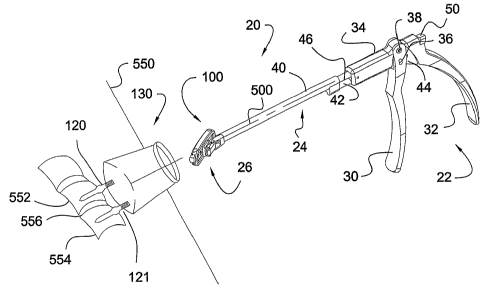
Refernng to Figs. 2 and 3, insertion instrument 20 will be described with
specific
reference to an implant 100 in the form of a plate attachable to anchors 120,
121 engaged
to vertebrae 552 and 554, respectively, of the spinal column of the patient.
Insertion
instrument 20 has a control system that includes a proximal handle assembly
22, and
connector and manipulator systems that include a shaft assembly 24 extending
distally
from handle assembly 22. Insertion instrument 20 further includes an implant
holder 26 at
the distal end of shaft assembly 24. Implant 100 is releasably mountable to
implant holder
26.
In Fig. 2, implant 100 may be rigidly mounted on insertion instrument 20 in a
first
position having a low profile orientation for insertion of implant 100 to a
surgical space in
a patient through pathway 130. In the reduced profile orientation,
longitudinal axis 510 of
implant 100 may be at any angle from 0 degrees to less than 90 degrees
relative to
longitudinal axis 500 of shaft assembly 24. For example, axis 510 may be
obliquely
oriented to and in the general direction of longitudinal axis 500 of shaft
assembly 24. In
the illustrated embodiment, implant 100 has a curved central axis 510,
although implants
with linear central axes are also contemplated. Other embodiments contemplate
that
central axis 510 of implant 100 could be coaxial with or parallel to
longitudinal axis 500 in
the reduced profile orientation. This reduced profile orientation minimizes
the footprint of
implant 100 relative to insertion instrument 20 and transverse to its
insertion path as
implant 100 is inserted through pathway 130 to the surgical space. After
insertion through
pathway 130, implant 100 is moved from its reduced profile insertion
orientation to a
desired orientation relative to anchors 120, 121 for engagement of implant 100
thereto.
CA 02485149 2004-11-03
WO 03/094741 PCT/US03/13292
9
In Figs. 4 and 5, handle assembly 22 is manipulated by the surgeon to actuate
implant holder 26 through shaft assembly 24 to move implant 100 to a second
position or
orientation with respect to insertion instrument 20, and also with respect to
anchors 120,
121. Implant 100 may be rigidly fixed to implant holder 26 throughout the
movement
from the first position to the second position. In the second, actuated
orientation,
longitudinal axis 510 of implant 100 extends more transversely to longitudinal
axis 500 of
shaft assembly 24 than when in the reduced profile orientation. It is
contemplated that the
actuated implant 100 is placed in the desired orientation for engagement of
implant 100
with anchors 120, 121. In the actuated orientation, the footprint of implant
100 in the
implant insertion direction through pathway 130 can be greater than the
opening of
pathway 130 at least adjacent skin level 550. Thus, the amount of tissue
dissection and
retraction required to accommodate insertion of implant 100 to the surgical
space is
minimized.
With implant 100 positioned in the desired position within the operative
space,
such as relative to anchors 120, 121, insertion instrument 20 can be detached
from implant
100 and removed from pathway 130. Handle assembly 22 may include a remote lock
mechanism for remotely securing and releasing implant 100 relative to
instrument 20.
Further instruments and implants such as set screws, nuts, sutures, anchors or
other
fastening elements can be inserted through pathway 130 to secure implant 100
at the
surgical space.
In the illustrated embodiment, the surgical space is associated with the spine
of the
patient, and implant 100 is a plate attachable to anchors 120 and 121 engaged
to vertebrae
552 and 554, respectively, on each either side of disc space 556. Pathway 130
is a
retractor sleeve that provides a protected working channel through skin 550 to
the surgical
space. The illustrated retractor sleeve is inserted in a cylindrical
configuration through
skin 550 and thereafter expandable to a frusto-conically shaped conftguration
to provide
access to each of the anchors 120, 121 at the distal end thereof through the
working
channel. The opening size of pathway 130 at skin 550 and to the surgical space
is
minimized to reduce the incision size and trauma to the surrounding tissue.
CA 02485149 2004-11-03
WO 03/094741 PCT/US03/13292
Pathway 130 can also be formed by non-expandable retractor sleeves or guide
sleeve, or by a micro-incision or open incision without a retractor sleeve, or
by tissue
retractors that do not form a sleeve. It is also contemplated that the tissue
through
pathway 130 can be sequentially dilated to form the desired pathway size while
minimizing trauma to the adjacent tissue. Endoscopic, microscopic or other
viewing
instruments and techniques are contemplated for viewing the surgical space.
One embodiment of the invention contemplates that implant 100 is a bone plate.
Other embodiments contemplated other implants, such as a rod, strut, linking
member,
bone fusion member, articulating member, or other implant in which it is
desirable to
10 minimize its profile for insertion through a pathway and thereafter alter
its orientation after
insertion through the pathway. Anchors 120, 121 can be bone screws or bolts
with
proximal ends adapted to receive implant 100 thereover or therein. Anchors
120, 121 can
also be bone screws that are multi-axial or uni-axial in form. Anchors 120,
121 can also
be, for example, in the form of hooks, staples, spikes, clamps, interbody
fusion devices,
interbody implants, intravertebral fusion device, or other intravertebral or
intervertebral
implant. The proximal ends of anchors 120, 121 to which implant 100 is engaged
can be a
threaded or unthreaded stem, U-shaped yoke or other receptacle or bearing
surface
configured for engagement with an implant 100. It is further contemplated that
implant
100 can be placed against or adjacent to the bone or tissue to which it is to
be engaged,
and then engaged thereto with anchors positioned after implant placement.
One specific application contemplates positioning the implant at a surgical
space
on or near the spine. Any one of a number of approaches to the spine are
contemplated,
including anterior, posterior, lateral, poster-lateral, antero-lateral
approaches, for example.
The insertion instrument can be employed in endoscopic, laparoscopic,
thorascopic or
other minimally invasive or open procedures. The implant can be attached to
bony
portions of the spine, including, for example, the vertebral bodies, vertebral
endplates,
pedicles, facet joints, or the various processes of the spine. Applications in
areas other
than spinal surgery are also contemplated.
Referring further to Figs. 2-6, handle assembly 22 includes distal handle
portion 30
pivotally coupled via a pin 38 to an extension 34 of a proximal handle portion
32. Shaft
CA 02485149 2004-11-03
WO 03/094741 PCT/US03/13292
11
assembly 24 includes an outer shaft 40 extending along axis 500 between handle
assembly
22 and implant holder 26. Distal handle portion 30 is engaged to an outer
shaft extension
42 (Fig. 2.) Outer shaft extension 42 extends proximally from outer shaft 40
through
extension 34, where it is coupled with distal handle portion 30 with pin 36.
An
intermediate shaft 46 is coupled to and extends proximally from extension 34
of proximal
handle portion 32. Distal handle portion 30 and proximal handle portion 32 can
be biased
via a spring or the like to the position shown in Fig. 2 so that outer shaft
40 is fully
extended distally relative to intermediate shaft 46. As distal handle portion
30 is moved
toward proximal handle portion 32, pin 36 moves proximally in groove 44 of
extension
34, axially translating outer shaft 40 proximally relative to intermediate
shaft 46 and
pivoting the implant holder.
Referring to Figs. 5-10, one embodiment of a lock system associated with
insertion
instrument 20 includes a cam member 48 extending through intermediate shaft
44, and a
lever 50 at a proximal end of intermediate shaft 44. Lever 50 is manipulated
by the
surgeon to move cam member 48 between an unlocked position, as shown in Figs.
7, 8 and
9, and a locked position, as shown in Figs. 2, 4, 5, 6 and 10. As discussed
further below,
cam member 48 is engageable with engagement members that couple the implant to
implant holder 26 of insertion instrument 20.
A linkage mechanism 52 is coupled between the distal end of outer shaft 40 and
implant holder 26. Linkage mechanism 52 includes a link 54 pivotally coupled
to a
bracket 56 extending laterally from the distal end of outer shaft 40. The
opposite end of
link 54 is pivotally coupled to a bracket 58 of implant holder 26. Implant
holder 26
further includes an articulating member 60 pivotally mounted to a mounting
portion 47 at
the distal end of intermediate shaft 46. Cam member 48 extends through
intermediate
shaft 46, including mounting portion 47. A pair of fingers 61, 62 extend
distally from
articulating member 60, forming a distal lip 63 therewith. Fingers 61, 62 each
include a
hole 64 (only one shown) therethrough.
A pair of engagement members 66, 67 are movably captured in mounting portion
47 of intermediate shaft 46. With cam member 48 in the unlocked position,
engagement
members 66, 67 can move into mounting portion 47 and recess below the outer
surfaces of
CA 02485149 2004-11-03
WO 03/094741 PCT/US03/13292
12
fingers 61, 62, as shown in Figs. 7 - 9. When cam member 48 is moved to its
locked
position with lever 50, cam member 48 contacts engagement members 66, 67 and
forces
each outwardly relative to mounting portion 47 and through the aligned holes
64 of fingers
61, 62, as shown in Figs. 4, 5, 6 and 10. Engagement members 66, 67 may have a
spherically shaped surface extending from forgers 61, 62 to allow the implant
to force the
engagement members into the recessed position to facilitate mounting,
dismounting and
locking of the implant. Engagement members 66, 67 can be provided with an
enlarged
shoulder (not shown) within mounting portion 47 that abuts mounting portion 47
when
engagement members 66, 67 extend from fingers 61, 62 to retain engagement
members
66, 67 therein.
With reference to Figs. 8-10, one embodiment of a method of mounting implant
100 on implant holder 26 of insertion instrument 20 will be described. Implant
100 may
include a receptacle 102 defined by a pair of upper rails 104, 105 and a pair
of lower rails
106, 107. Slidably positioned between rails 104, 105 and rails 106, 107 are
slide washers
108, 109. Washers 108, 109 each have a hole therethrough sized to receive an
anchor to
couple implant 100 to a bony segment, such as adjacent vertebrae 552 and 554.
Washers
108, 109 can be slidably adjusted along the upper and lower rails and
positioned at the
desired location in the plate based on the anchor spacing. It is further
contemplated that
implant 100 can include more than two washers 108, 109. It should be
understood that
implant 100 can be any type of plate or implant which has a receptacle sized
to receive
implant holder 26. Other embodiments contemplate that implant 100 does not
include a
receptacle, but rather the insertion instrument is coupled to the implant via
other means.
For example, the implant holder could be clamped around the implant or a
portion of the
implant, or the implant holder could be fastened to the implant.
As shown in Fig. 8, implant 100 is mounted to insertion instrument 20 by
inserting
holding portion 26 into receptacle 102 of the implant. To mount implant 100 on
holding
portion 26, it may be desirable for insertion instrument to be placed in its
actuated
condition. Thus, distal handle portion 30 can be moved toward proximal handle
portion
32 to translate outer shaft 40 proximally along intermediate shaft 46. This
causes linkage
mechanism 52 to pivot so that link 54 extends along intermediate shaft 46,
pulling the side
CA 02485149 2004-11-03
WO 03/094741 PCT/US03/13292
13
of articulating member 60 coupled to link 52 proximally as well. To insert
implant holder
26 into receptacle 102, lever 50 is moved to its unlocked position (Fig. 7)
thereby moving
cam member 48 to its unlocked position, allowing engagement members 66, 67 to
move
inwardly into mounting portion 47 and below the outer surface of fingers 61,
62. Fingers
61, 62 are inserted into receptacle 102, as shown in Fig. 9, to a depth that
allows
engagement members 66, 67 to contact implant 100, such as until lip 63 is
positioned
adjacent the upper or proximal surface of implant 100.
Once fingers 61, 62 are inserted in receptacle 102 of implant 100, lever 50 is
moved to its locked position, thus rotating cam member 48 and pushing
engagement
members 66, 67 out respective ones of the holes 64, as shown in Fig. 10. The
outwardly
biased engagement members 66, 67 form an expansion lock with the interior
portion of
implant 100, such as by contacting the underside of upper rails 104, 105 to
prevent implant
100 from being removed from implant holder 26. Once implant 100 is engaged to
insertion instrument 100, distal handle portion 30 of handle assembly 22 can
be released
so that outer shaft 40 moves distally along intermediate shaft 46 to its
unactuated position.
In the unactuated position, link 54 pushes the side of articulating member 60
to which it is
pivotally attached distally, causing articulating member 60 to pivot about
mounting
portion 47. The pivoting of articulating member 60 also pivots implant 100 so
that its
central axis 510 extends at any angle from 0 degrees to less than 90 degrees
relative to axis
500, such as extending obliquely to or in the general direction of
longitudinal axis 500 of
insertion instrument 20, as shown in Figs. 2 and 3.
In its unactuated position, implant 100 has a reduced profile such that its
footprint
transverse to longitudinal axis 500 is minimized. In this position, implant
100 can be
inserted in a minimally invasive access pathway to the surgical site. Once
inserted
through the pathway to the surgical site, distal handle portion 30 of handle
assembly 22 is
moved toward proximal handle portion 32, translating outer shaft 40 proximally
along
intermediate shaft 46. This in turn actuates linkage mechanism 52, which pulls
the side of
articulating member 60 to which it is attached proximally. This pivots
articulating
member 60 about mounting portion 47 to position implant 100 in its desired
orientation
relative to anchors 120, 121, as shown in Figs. 4 and 5, so that implant 10
can be engaged
CA 02485149 2004-11-03
WO 03/094741 PCT/US03/13292
14
thereto. Once implant 100 is in its desired position at the surgical site,
lever 50 can be
moved to its unlocked position, which remotely rotates cam member 4S to its
orientation
in Figs. 8 and 9. Engagement members 66, 67 can then easily slide through
holes 64 and
into mounting portion 47 so that implant holder 26 can be withdrawn from
receptacle 102.
Implant 100 can be released in the surgical space in a substantially
unconstrained
condition, and thereafter constrained or secured as desired. Insertion
instrument 20 could
also release implant 100 in a constrained condition provided by substantial
contact
between implant 100 and the anatomy, bone fastener or the like positioned in
the surgical
space.
Refernng now to Figs. 11-19 there is illustrated another embodiment insertion
instrument designated at 220. Insertion instrument 220 includes components
corresponding to those of insertion instrument 20 discussed above, and like
components
between instruments 20 and 220 are designated with the same reference
numerals.
Insertion instrument 220 includes a handle assembly 22, a shaft assembly 24
and an
implant holder 76 at the distal end of shaft assembly 24. Implant holder 76 is
configured
to clamp or grip surfaces of the implant. In the illustrated embodiment,
implant 200 is in
the form of a spinal rod gripped by implant holder 76. Other embodiments
contemplate
other types of implants, such as plates, fusion members, articulating members,
or anchors
for example, that could be gripped by implant holder 76.
Implant 200 is releasably mounted to insertion instrument 220 with implant
holder
76. In Fig. 11, implant 200 is positioned on insertion instrument 220 in a
first position
having a reduced profile orientation for insertion to a surgical space in a
patient through a
pathway, as discussed above. In the reduced profile orientation, longitudinal
axis 610 of
implant 200 extends at any angle, except perpendicular, such as obliquely to
and in the
general direction of longitudinal axis 500 of shaft assembly 24. This
minimizes the
footprint of implant 200 relative to insertion instrument 220 for insertion
implant 200
through the pathway. In the illustrated embodiment, implant 200 has a curved
central axis
510, although implants with linear central axes are also contemplated. Other
embodiments
contemplate that central axis 610 of implant 200 could be coaxial with or
parallel to
longitudinal axis 600 in the reduced profile orientation.
CA 02485149 2004-11-03
WO 03/094741 PCT/US03/13292
After insertion through pathway 130, implant 200 can be moved from its low
profile insertion orientation to an enlarged profile orientation that allows
it to be coupled
to anchors, such as spinal hooks, bone screws with an implant receptacle, or
other implant
engaging member. In Figs. 12 and 13, handle assembly 22 is manipulated to
actuate
implant holder 76 through shaft assembly 24 to the enlarged profile
orientation with
respect to insertion instrument 220. In the second, enlarged profile
orientation,
longitudinal axis 610 of implant 200 extends transversely with respect to
longitudinal axis
600 of shaft assembly 24 and also transversely to the direction of insertion
of implant 200.
The actuated implant 200 is placed in the desired orientation for engagement
of implant
10 200 at the surgical space.
In the enlarged profile orientation, implant 200 can have a footprint in the
implant
insertion direction through the pathway that is greater than the transverse
dimension
defining the opening of the pathway at least adjacent skin level 550. However,
when
coupled to insertion instrument 220 in the reduced profile orientation,
implant 200 can
15 pass through the pathway. Thus, the amount of tissue dissection and
retraction required to
accommodate insertion of implant 200 is minimized. With implant 200 in the
desired
position, insertion instrument 220 can be detached from implant 200 and
removed from
the pathway.
In Fig. 15 there is shown the distal end of shaft assembly 24. Intermediate
shaft 46
includes a mounting portion 47 having a hole 49 formed therethrough. An
engagement
member 80 extends through hole 49, and has an enlarged sh~ulder (not shown) to
retain
engagement member 80 in mounting portion 47. A similar second engagement
member
81 can be provided through a hole (not shown) on the opposite side of mounting
portion
47. Cam member 48, shown in an unlocked position in Fig. 15, extends through
mounting
portion 47 and is contactable with engagement members 80, 81.
In Fig. 16, an articulating member 78 is pivotally mounted on mounting portion
47.
Articulating member 78 includes a bracket 79 pivotally coupled to the distal
end of link 54
of linkage mechanism 52. The opposite end of link 54 is pivotally mounted to
bracket 56
extending from the distal end of outer shaft 40. Articulating member 78
includes first and
second fingers 82, 83 extending distally therefrom. In Fig. 16, cam member 48
(along
CA 02485149 2004-11-03
WO 03/094741 PCT/US03/13292
16
with lever 50) is in its unlocked position. In Fig. 17, cam member 48 (along
with lever 50)
has been moved to its locked position, wherein engagement members 80, 81
extend
through the holes 77 (only one shown in Figs. 16, 17) in articulating member
78.
In Fig. 18, first and second clamp members 84, 85 are pivotally mounted to
fingers
82, 83 of articulating member 78. A hinge 86 can be provided between clamp
members
84, 85 for movement of each clamp member either toward each other or away from
each
other as indicated by arrows 620. Clamping surfaces 88, 89 of respective ones
of the
clamp members 84, 85 may be moved toward one another to grip the implant by
moving
cam member 48 to its locked position so that cam member 48 acts on engagement
members 80, 81. As shown in Fig. 19, as the engagement members 80, 81 extend
through
articulating member 78, the engagement members 80, 81 contact the proximal
ends of
clamp members 84, 85 to move the proximal ends away from one another and move
the
distal ends of clamp members 84, 85 toward one another.
When cam member 48 is unlocked, engagement members 80, 81 can recess into
mounting portion 47. Clamping surfaces 88, 89 of clamp members 84, 85 can move
away
from one another to release the implant as insertion instrument 220 is
withdrawn.
Alternatively, cam member 48 and engagement members 80, 81 may be connected,
such
as by including corresponding gear teeth, so as to positively unlock clamp
members 84,
85. Implant 200 can be released in the surgical space in a substantially
unconstrained
condition, and thereafter constrained or secured as desired. Insertion
instnunent 220 could
also release implant 200 in a constrained condition provided by substantial
contact
between implant 200 and the anatomy, bone fastener or the like positioned in
the surgical
space.
While the invention has been illustrated and described in detail in the
drawings and
foregoing description, the same is to be considered as illustrative and not
restrictive in
character, it being understood that only the preferred embodiments have been
shown and
described and that all changes and modifications that come within the spirit
of the
invention are desired to be protected.