Language selection

Search

Patent 2485236 Summary

Third-party information liability

Some of the information on this Web page has been provided by external sources. The Government of Canada is not responsible for the accuracy, reliability or currency of the information supplied by external sources. Users wishing to rely upon this information should consult directly with the source of the information. Content provided by external sources is not subject to official languages, privacy and accessibility requirements.

Claims and Abstract availability

Any discrepancies in the text and image of the Claims and Abstract are due to differing posting times. Text of the Claims and Abstract are posted:

  • At the time the application is open to public inspection;
  • At the time of issue of the patent (grant).
(12) Patent Application: (11) CA 2485236
(54) English Title: ELECTRICAL INSULATION ARRANGEMENTS FOR ELECTRIC FANS, MOTOR ASSEMBLIES AND CONTROLS THEREFOR
(54) French Title: TROUSSES D'ISOLATION ELECTRIQUE POUR VENTILATEURS ELECTRIQUES, MOTEURS ELECTRIQUES ET COMMANDES CONNEXES
Status: Dead
Bibliographic Data
(51) International Patent Classification (IPC):
  • H02K 5/08 (2006.01)
  • F04D 25/06 (2006.01)
  • F04D 25/08 (2006.01)
  • F04D 29/52 (2006.01)
  • F04D 29/64 (2006.01)
  • H02K 5/00 (2006.01)
(72) Inventors :
  • CHEN, YUNG (United States of America)
  • BAIN, BENJAMIN (United States of America)
  • ALMANZA, MANUEL (United States of America)
(73) Owners :
  • LAKEWOOD ENGINEERING AND MANUFACTURING CO. (United States of America)
(71) Applicants :
  • LAKEWOOD ENGINEERING AND MANUFACTURING CO. (United States of America)
(74) Agent: SMART & BIGGAR
(74) Associate agent:
(45) Issued:
(22) Filed Date: 2004-10-19
(41) Open to Public Inspection: 2005-04-29
Availability of licence: N/A
(25) Language of filing: English

Patent Cooperation Treaty (PCT): No

(30) Application Priority Data:
Application No. Country/Territory Date
10/696,647 United States of America 2003-10-29

Abstracts

English Abstract


The present invention generally provides electrical insulation arrangements
for
electric fans, motor assemblies and controls therefor. According to a
particular aspect of
the invention, an electric motor for an electric fan having a fan housing is
provided. The
motor comprises a motor casing having an insulator mounting arrangement
configured
for mounting the motor to the fan housing. The mounting arrangement comprises
a
mounting portion of the motor casing, and an insulating member mounted to the
mounting portion of the motor casing without a separate fastener. The
insulating
member is configured to accept a fastener that can be utilized to mount the
motor casing
to the fan housing such that the fan housing would be insulated from the motor
casing.
Other aspects are also provided.


Claims

Note: Claims are shown in the official language in which they were submitted.


12

Claims

What is claimed is:

1. An electric motor for an electric fan having a fan housing, the motor
comprising a motor casing having an insulator mounting arrangement configured
for
mounting the motor to the fan housing, the mounting arrangement comprising:
a mounting portion of the motor casing; and
an insulating member mounted to the mounting portion of the motor casing
without a separate fastener;
the insulating member configured to accept a fastener that can be utilized to
mount the motor. casing to the fan housing such that the motor casing and the
fan housing
are insulated from each other.
2. The electric motor of claim 1, wherein the insulating member includes a
base
portion and a protrusion extending therefrom, the protrusion being mounted to
the
mounting portion of the motor casing.
3. The electric motor of claim 1, wherein at least a portion of the insulating
member
is disposed within a mounting aperture disposed within the mounting portion of
the
motor casing.
4. The electric motor of claim 2, wherein the base portion of the insulating
member
is disk shaped.
5. The electric motor of claim 2, wherein the protrusion includes a hole
therein to
accept the fastener.


13
6. The electric motor of claim 3, wherein the portion of the insulating member
is
securely fit within the mounting aperture of the motor casing.

7. The electric motor of claim 3, wherein the portion of the insulating member
is
press-fit within the mounting aperture of the motor casing.

8. The electric motor of claim 1, wherein a general point of
the mounting of the insulator member to the motor casing.

9. The electric motor of claim 8, wherein the insulating member accepts the
fastener
at the general point of attachment.

10. The electric motor of claim 1, further comprising:
a second mounting portion of the motor casing; and

a second insulating member mounted to the second mounting portion of the motor
casing without a separate fastener;

the second insulating member configured to accept a second fastener that can
be
utilized to mount the motor casing to the fan housing such that the motor
casing and the
fan housing are insulated from each other.

11. The electric motor of claim 1, wherein the insulating member is further
configured to insulate the fastener from the motor casing when the motor
casing is
mounted to the fan housing.

12. An insulated mounting arrangement for mounting an electric motor to a fan
housing of an electric fan, the arrangement comprising:

a mounting portion of a motor casing of the electric motor;


14
an insulating member mounted to the mounting portion of the motor casing
without a separate fastener; and

a fastener disposed through a portion of the fan housing and within the
insulating
member such that the fan housing is insulated from the motor casing.

13. The arrangement of claim 12, wherein the insulating member includes a base
portion and a protrusion extending therefrom, the protrusion being mounted to
the
mounting portion of the motor casing.

14. The arrangement of claim 13, wherein the protrusion includes a hose
therein to
accept the fastener.

15. The arrangement of claim 12, wherein at least a portion of the insulating
member
is disposed within a mounting aperture disposed within the mounting portion of
the
motor casing.

16. The arrangement of claim 15, wherein the portion of the insulating member
is
securely fit within the mounting aperture of the motor casing.

17. The arrangement of claim 15, wherein the portion of the insulating member
is
press-fit within the mounting aperture of the motor casing.

18. The arrangement of claim 12, wherein a general point of attachment is
defined by
the mounting of the insulator member to the motor casing.

19. The arrangement of claim 18, wherein the insulating member accepts the
fastener
at the general point of attachment.


15


20. The arrangement of claim 12, further comprising:
a second mounting portion of the motor casing of the electric motor;
a second insulating member mounted to the second mounting portion of the motor
casing without a separate fastener; and
a second fastener disposed through a second portion of the fan housing and
within
the second insulating member such that the second fastener is insulated from
the motor
casing.

21. The arrangement of claim 12, wherein the insulating member insulates the
fastener from the motor casing.

22. An electric motor for an electric fan having a fan housing, the motor
comprising a motor casing having an insulator mounting arrangement configured
for
mounting the motor to the fan housing, the mounting arrangement comprising:
a mounting portion of the motor casing; and
an insulating member mounted to the mounting portion of the motor casing
without a separate fastener to define a general point of attachment;
the insulating member configured to accept a fastener that can be utilized to
mount the motor casing to the fan housing at the general point of attachment
such that the
motor casing would be insulated from the fan housing.

23. The electric motor of claim 22, wherein at least a portion of the
insulating
member is mounted within an aperture within the mounting portion of the motor
casing.

24. The electric motor of claim 23, wherein the portion of the insulating
member is
press-fit into the aperture.


16
25. An insulated mounting arrangement for mounting an electric motor to a fan
housing of an electric fan, the arrangement comprising:
a mounting portion of a motor casing of the electric motor;
an insulating member mounted to the mounting portion of the motor casing
without a separate fastener to define a general point of attachment; and
a fastener disposed through a portion of the fan housing and within the
insulating
member at the point of attachment such that the fan housing is insulated from
the motor
casing.

26. The arrangement of claim 25, wherein the fastener is insulated from the
motor
casing by the insulating member.

27. The arrangement of claim 25; wherein at least a portion of the insulating
member
is mounted within an aperture within the mounting portion of the motor casing.

28. The arrangement of claim 26, wherein the portion of the insulating member
is
press-fit into the aperture.

29. An electric motor for an electric fan having a fan housing, the motor
comprising a
motor casing having an insulator mounting arrangement configured for mounting
the
motor to the fan housing, the mounting arrangement comprising:
a mounting portion of the motor casing having a mounting aperture therein; and
an insulating member having at least a portion disposed within the mounting
aperture to define a general point of attachment to the motor casing;
the insulating member configured to accept a fastener disposed through a
portion
of the fan housing at the point of attachment such that the fan housing and
the fastener
would be insulated from the motor casing.


17
30. An insulated mounting arrangement for mounting an electric motor to a fan
housing of an electric fan, the arrangement comprising:
a mounting portion of a motor casing of the motor having a mounting aperture
therein;
an insulating member having at least a portion disposed within the mounting
aperture of the motor casing; and
a fastener disposed through a portion of the fan housing and within the
insulating
member such that the fan housing and the fastener are insulated from the motor
casing.

31. The mounting arrangement of claim 30, wherein the insulating member
includes a
base portion and a protrusion extending therefrom, the protrusion being
disposed within
the mounting aperture of the motor casing.

32. The mounting arrangement of claim 31, wherein the base portion of the
insulating
member is disk shaped.

33. The mounting arrangement of claim 31, wherein the protrusion includes a
hole
therein to accept the fastener.

34. The mounting arrangement of claim 30, wherein the portion of the
insulating
member is securely fit within the mounting aperture of the motor casing.

35. The mounting arrangement of claim 30, wherein the portion of the
insulating
member is press-fit within the mounting aperture of the motor casing.

36. The mounting arrangement of claim 30, further comprising:
a second mounting portion of the motor casing of the motor having a mounting
aperture therein;


18


a second insulating member having at least a portion disposed within the
mounting aperture of the second mounting portion of the motor casing; and
a second fastener disposed through a second portion of the fan housing and
within
the second insulating member such that the fastener is insulated from the
motor casing.

37. An electric motor for an electric fan having a fan housing, the motor
comprising a
motor casing having an insulator mounting arrangement configured for mounting
the
motor to the fan housing, the mounting arrangement comprising four insulating
members
each mounted to the motor casing without a separate fastener to define four
general
points of attachment, each of the insulating members configured to accept a
fastener that
can be utilized to mount the motor casing to the fan housing at the general
points of
attachment such that the fan housing would be insulated from the motor casing.

38. An insulator member configured for use in mounting an electric motor to a
housing of an electric fan assembly, the motor including a motor casing having
at least
one mounting aperture, the insulator member comprising:
a base portion having a mounting surface; and
a protrusion extending from the base portion, the protrusion configured to be
securely disposed within the mounting aperture of the motor casing;
wherein the mounting surface of the base portion is arranged to oppose a
mounting surface of the housing when the motor is mounted to the housing by a
fastener
that passes through the mounting surface of the housing and penetrates the
base portion
and the protrusion, the fastener being insulated from the motor casing when
the motor is
mounted.

39. The insulator member of claim 38, wherein the protrusion is configured to
be
press-fit into the mounting aperture of the motor casing.


19
40. The insulator member of claim 38, wherein the protrusion includes a hole
therein
to accept the fastener.
41. The insulator member of claim 40, wherein the hole is configured to accept
a
thread-forming fastener.
42. The insulator member of claim 38, wherein the base portion having the
mounting
surface has a disk shape.
43. An insulated mounting arrangement for mounting an electric motor to a fan
housing of an electric fan, the arrangement comprising:
a mounting portion of a motor casing of the motor having a mounting aperture
therein;
an insulating member having a base portion and a protrusion extending
therefrom,
the protrusion disposed within the mounting aperture of the motor casing; and
a fastener disposed through a portion of the fan housing and within the
protrusion
such that the fan housing and the fastener are insulated from the motor
casing.

44. The mounting arrangement of claim 43, further comprising:
a second mounting portion of the motor casing of the motor having a mounting
aperture therein;
a second insulating member having a base portion and a protrusion extending
therefrom, the protrusion disposed within the mounting aperture of the second
mounting
portion of the motor casing; and
a second fastener disposed through a second portion of the fan housing and
within
the protrusion of the second insulating member such that the fan housing and
the second
fastener are insulated from the motor casing.


20
45. An electric motor for an electric fan having a fan housing, the motor
comprising a
motor casing having an insulator mounting arrangement configured for mounting
the
motor to the fan housing, the mounting arrangement comprising four insulating
members
each mounted to the motor casing, each of the insulating members configured to
accept a
fastener that can be utilized to mount the motor casing to the fan housing
such that the
fan housing would be insulated from the motor casing.

46. The motor of claim 45, wherein the insulating members are further
configured
such that the fastener would be insulated from the motor casing when the motor
casing is
mounted to the fan housing.

47. An electric fan comprising a fan housing having a peripheral shroud
portion and
two grill portions each disposed adjacent the shroud portion, the shroud
portion and the
grill portions defining an interior region of the fan housing within which a
motorized
blade assembly is disposed, the motorized blade assembly including at least
two
insulating members mounted thereto, the motorized blade assembly mounted to
the fan
housing via at least two fasteners each disposed through the fan housing and
within one
of the insulating members such that the fan housing is insulated from the
motor casing.

48. The electric fan of claim 47, wherein each of the fasteners are insulated
from the
motor casing.

49. An electric fan comprising a fan housing having a peripheral shroud
portion and
two grill portions each disposed adjacent the shroud portion, the shroud
portion and the
grill portions defining an interior region of the fan housing within which a
motorized
blade assembly is disposed, the motorized blade assembly including at least
two
mounting holes and at least two insulating members each disposed within one of
the
mounting holes, the motorized blade assembly mounted to the fan housing via at
least


21
two fasteners each disposed through the fan housing and within one of the
insulating
members such that the fan housing is insulated from the motor casing.

50. The electric fan of claim 49, wherein each of the fasteners are insulated
from the
motor casing.

51. An electric fan comprising a fan housing having a peripheral shroud
portion and a
front and a rear grill portion each disposed adjacent the shroud portion, the
shroud
portion and the grill portions defining an interior region of the fan housing
within which
a motorized blade assembly is mounted to a motor mount portion of the fan
housing such
that the motorized blade assembly is electrically insulated from the fan
housing, the
motorized blade assembly including a motor having a motor casing, the motor
casing
having a vented rear surface disposed adjacent to the rear grill portion, the
rear grill
portion having a first mesh portion defined by a plurality of openings within
the rear grill
portion, the first mesh portion disposed adjacent to the vented rear surface
of the motor
casing, the openings of the first mesh portion dimensioned such that a users
finger cannot
pass therethrough and contact the motor casing while allowing sufficient air
flow
therethrough to cool the motor.

52. The electric fan of claim 51, the rear grill portion further including a
solid surface
portion disposed adjacent the motor mount portion of the fan housing where the
blade
assembly is mounted.

53. An insulated mounting arrangement for mounting an electric motor to a fan
housing of an electric fan, the arrangement comprising:
a mounting portion of a motor casing of the motor;
an insulating member connected to the mounting portion of the motor casing;
and
a motor mount portion of the fan housing;


22
the insulating member configured to directly engage the motor mount portion of
the fan housing without a separate fastener such that the engagement
electrically insulates
the fan housing from the motor casing.

54. An electric motor for an electric fan having a fan housing, the motor
comprising a motor casing having an insulator mounting arrangement configured
for
mounting the motor to the fan housing, the mounting arrangement comprising:
a mounting portion of the motor casing having a mounting aperture therein; and
an insulating member having at least a portion disposed within the mounting
aperture;
the insulating member configured to accept a fastener disposed through a
portion
of the fan housing such that the fastener is insulated from the motor casing.

55. The motor of claim 54, wherein the insulating member includes an aperture
configured to accept the fastener.

56. The motor of claim 55, wherein the aperture of the insulating member is a
hole that is substantially concentrically positioned with respect to the
mounting
aperture.

57. The motor of claim 54, wherein the insulating member includes a base
portion
and a protrusion extending therefrom, the protrusion being disposed within the
mounting
aperture of the motor casing.

58. The motor of claim 54, wherein the portion of the insulating member
disposed
within the mounting aperture is press-fit therein.


23

59. An electric motor for an electric fan having a fan housing, the motor
comprising a motor casing having an insulator mounting arrangement configured
for
mounting the motor to the fan housing, the mounting arrangement comprising:
at least two mounting portions of the motor casing each having a mounting
aperture therein; and
at least two insulating members each having at least a portion disposed within
one
of the mounting apertures;
each of the insulating members configured to accept a fastener disposed
through a
portion of the fan housing such that the fastener is insulated from the motor
casing.
60. An electric fan comprising:
a fan housing; and
a motorized blade assembly disposed within the fan housing, the motorized
blade
assembly including an electric motor having a motor casing, the motor casing
having a
mounting portion having a mounting aperture therein and an insulating member
having at
least a portion disposed within the mounting aperture to define a general
point of
attachment to the motor casing, the insulating member having a fastener
received therein
at the general point of attachment such that the fastener is insulated from
the motor
casing, the fastener being disposed through a portion of the fan housing to
facilitate
attachment of the motor to the fan housing.
61. An electric fan having at least one control, the fan comprising:
a fan housing; and
a control casing attached to the fan housing and configured to house the at
least
one control of the fan, the casing configured to electrically isolate the at
least one control
from the fan housing.


24

62. A control module for an electric fan having a fan housing, the control
module
comprising:
at least one control configured to be connectable to an electrical circuit
associated
with the fan; and
a casing having an interior portion containing the at least one control
associated
with the fan, the casing configured to be attachable to the fan housing and
configured to
electrically insulate the at least one control from the fan housing when it is
attached to the
fan housing, while allowing access to the control by a user of the fan.

63. An electric fan comprising:
a fan housing;
a motorized blade assembly disposed within the fan housing, the motorized
blade
assembly including an electric motor having a motor casing mounted to the fan
housing;
an insulating member disposed between the fan housing and the motor casing to
electrically insulate the motor casing from the fan housing;
at least one control associated with an electrical circuit of the fan; and
a casing having an interior portion containing the at least one control
associated
with the fan, the casing mounted to the fan housing and configured to
electrically insulate
the at least one control from the fan housing.

64. An insulated mounting arrangement for mounting an electric motor to a fan
housing of an electric fan, the arrangement comprising:
a first and a second mounting portion of a motor casing of the motor;
a first insulating member mounted to the first mounting portion of the motor
casing;
a second insulating member mounted to the second mounting portion of the motor
casing;


25

a first fastener disposed through a first portion of the fan housing and the
first
insulating member; and
a second fastener disposed through a second portion of the fan housing and the
second insulating member;
wherein the motor casing is insulated from the fan housing.
65. An electric motor for an electric fan having a fan housing, the motor
comprising a motor casing having an insulator mounting arrangement configured
for
mounting the motor to the fan housing, the mounting arrangement comprising:
a first and a second mounting portion of a motor casing of the motor;
a first insulating member mounted to the first mounting portion of the motor
casing;
a second insulating member mounted to the second mounting portion of the motor
casing;
the first insulating member configured to accept a first fastener utilized
when the
motor casing is mounted to the fan housing; and
the second insulating member configured to accept a second fastener utilized
when the motor casing is mounted to the fan housing;
wherein the motor casing is insulated from the fan housing when mounted
thereto.
66. An insulated mounting arrangement for mounting an electric motor to a fan
housing of an electric fan, the arrangement comprising:
a mounting portion of a motor casing of the electric motor;
an insulating member mounted to the fan housing; and
a fastener disposed through the insulating member and within the mounting
portion of the motor casing such that the fan housing is insulated from the
motor casing
and the fastener.


26

67. The arrangement of claim 66, wherein the insulating member is mounted to
the
fan housing without a fastener.
68. The arrangement of claim 66, wherein the insulating member is mounted
within
an aperture within the fan housing.
69. The arrangement of claim 66, wherein the insulating member comprises a
first
portion disposed between the motor casing and the fan housing and a second
portion
disposed between the fan housing and the fastener.
70. The arrangement of claim 66, further comprising:
a second mounting portion of the motor casing of the electric motor;
a second insulating member mounted to the fan housing; and
a second fastener disposed through the second insulating member and within the
second mounting portion of the motor casing such that the fan housing is
insulated from
the motor casing and the second fastener.
71. An electric fan having a fan housing and a motor, the motor comprising a
motor
casing having an insulator mounting arrangement configured for mounting the
motor to
the fan housing, the mounting arrangement comprising four insulating members
each
mounted to the fan housing, each of the insulating members configured to
accept one of
four fasteners that mount the motor casing to the fan housing such that the
fan housing is
insulated from the motor casing.
72. The electric fan of claim 71, wherein each of the fasteners are insulated
from the
fan housing.


27

73. The electric fan of claim 71, wherein the insulating member comprises a
first
portion disposed between the motor casing and the fan housing and a second
portion
disposed between the fan housing and the fastener.

Description

Note: Descriptions are shown in the official language in which they were submitted.


CA 02485236 2004-10-19
Attorney Docket No. 547 P 109 PATENT
ELECTRICAL INSULATION ARRANGEMENTS FOR
ELECTRIC FANS, MOTOR ASSEMBLIES AND CONTROLS THEREFOR
Technical Field
[0001] The invention relates to electric fans, and more particularly to
electric fans having
electric motor assemblies and related components mounted therein.
Background of the Invention
[0002] Electric fans of all types have traditionally been an effective way to
provide
climate control within a living space. During the summer months, electric fans
provide a
very low cost solution to keep air circulating within a living space, and
hence, help keep
temperatures from reaching uncomfortable, and sometimes dangerous, levels. In
recent
years, electric fans have been made increasingly efficient and more powerful
through
advancements in electric motor technology. Many electric fans today, such as
box fans,
incorporate four pole and six pole split capacitor motor technology. While
this
technology increases efficiency and power, it does require relatively higher
operating
voltages.
[0003] While existing electric fan assemblies have all been designed to be
safe for their
intended use, it is desirable to not only meet, but exceed safety standards
set by various
organizations, including independent organizations such as Underwriters
Laboratories
(LTL). With this goal in mind, it is desirable to electrically isolate
electric motors from
other portions of the fan assembly. This is especially true when the fan is
being operated
in very humid conditions or when the air being moved by the fan has high
moisture
content. Condensation caused by the air can create a current leakage pathway
between
the fan motor and other parts of the fan, such as ~ metallic shroud of a
typical box-type
fan. In such cases, these other parts of the fan can become electrically
charged.
Electrical isolation of the fan motor prevents such occurrences.
[0004] Presently-known attempts at electrical isolation have many drawbacks.
For
example, U.S. Patent No. 6,309,192 discloses an insulated box fan that employs
a plastic


CA 02485236 2004-10-19
2
isolator ring that is attached to the fan housing at a first set of points and
separately
attached to the fan motor at a second set of points. The attachments are
implemented
with screws. One problem associated with this fan is the difficulty in
alignment of the
attachment points between the isolator ring and the motor. This difficulty is
created by
the ring being a single component having multiple attachment points. Because
all of the
attachment points are fixed to a single component, alignment of the attachment
points are
linked together, thereby creating alignment and tolerance constraints. This
creates
manufacturing quality concerns. Furthermore, because the isolator ring is a
single
component, it is more susceptible to manufacturing defects caused by
inconsistencies
between each of the attachment points, dimensional or otherwise. Another
problem is
the cost of the components and the assembly. Because of the multiple
attachment points,
the number of screws needed for the attachment points, the size of the
isolator ring, and
other factors, the assembly is relatively costly.
[0005] It has also been found that a combination of insulating solutions can
be more
effective than merely incorporating an insulator between the motor and the fan
housing as
shown in the '192 patent. Among its other shortcomings, the '192 patent does
not
disclose any such additional insulating solutions.
Summary of the Invention
[0006] The present invention generally provides electrical insulation
arrangements for
electric fans, motor assemblies and controls therefor.
[0007] According to a particular aspect of the present invention, an electric
motor for an
electric fan having a fan housing is provided. The motor comprises a motor
casing
having an insulator mounting arrangement configured for mounting the motor to
the fan
housing. The mounting arrangement comprises a mounting portion of the motor
casing,
and an insulating member mounted to the mounting gortion of the motor casing
without a
separate fastener. The insulating member is configured to accept a fastener
that can be
utilized to mount the motor casing to the fan housing such that the motor
casing and the
fan housing are insulated from each other.


CA 02485236 2004-10-19
3
[0008] According to another aspect, an insulated mounting arrangement for
rriounting an
electric motor to a fan housing of an electric fan is provided. The
arrangement comprises
a mounting portion of the motor casing, an insulating member mounted to the
mounting
portion of the motor casing without a separate fastener, and a fastener
disposed through a
portion of the fan housing and within the insulating member such that the
fastener,is
insulated from the motor casing.
[0009] According to another aspect, an electric motor for an electric fan
having a fan
housing is provided. The motor comprises a motor casing having an insulator
mounting
arrangement configured for mounting the motor to the fan housing. The mounting
arrangement comprises a mounting portion of the motor casing, and an
insulating
member mounted to the mounting portion of the motor casing without a separate
fastener
to define a general point of attachment. The insulating member is configured
to accept a
fastener that can be utilized to mount the motor casing to the fan housing at
the general
point of attachment such that the fastener would be insulated from the motor
casing.
[0010] According to yet another aspect, an insulated mounting arrangement for
mounting
an electric motor to a fan housing of an electric fan is generally provided.
In one
embodiment, the arrangement includes a mounting portion of a motor casing of
the motor
having a mounting aperture therein, an insulating member having at least a
portion
disposed within the mounting aperture of the motor casing, and a screw
disposed through
a portion of the fan housing and Within the insulating member such that the
screw is
insulated from the motor casing.
[0011] According to another aspect, the insulating member includes a base
portion and a
protrusion extending therefrom, the protrusion being mounted to the mounting
portion of
the motor casing. In a particular embodiment, the protrusion in press-fit into
a mounting
aperture within the mounting portion of the motor casing.
[OOI2] According to yet another aspect, an insulated mounting arrangement foi
mounting
an electric motor to a fan housing of an electric fan is provided where the
arrangement
includes a mounting portion of a motor casing of the motor, an insulating
member


CA 02485236 2004-10-19
4
connected to the mounting portion of the motor casing, and a motor mount
portion of the
fan housing. The insulating member is configured to directly engage the motor
mount
portion of the fan housing without separate fasteners. The engagement
electrically
insulates the fan housing from the motor casing.
[0013] According to yet another aspect, an electric fan is provided comprising
a fan
housing having a peripheral shroud portion and a front and a rear grill
portion each
disposed adjacent the shroud portion. The shroud portion and the grill
portions define an
interior region of the fan housing within which a motorized blade assembly is
mounted to
a motor mount portion of the. fan housing such that the motorized blade
assembly is
electrically insulated from the fan housing. The motorized blade assembly
includes a
motor having a motor casing. The motor casing includes a vented rear surface
disposed
adjacent to the rear grill portion. The rear grill portion includes a first
mesh portion and a
second mesh portion defined by a plurality of openings within the rear grill
portion. The
second mesh portion is disposed adjacent to the vented rear surface of the
motor casing.
The openings of the second mesh portion are dimensioned such that a user's
finger
cannot pass therethrough and contact the motor casing while allowing
sufficient air flow
to cool the motor.
[0014] According to another aspect, an electric fan having at least one
control is
provided. The fan comprises a fan housing and a control casing attached to the
fan
housing and configured to house the at least one control of the fan. The
casing is
configured to electrically isolate the at least one control from the fan
housing.
(0015] According to yet another aspect, an insulated mounting arrangement for
mounting
an electric motor to a fan housing of an electric fan is provided. The
arrangement
comprises a mounting portion of a motor casing of the electric motor, an
insulating
member mounted to the fan housing, and a fastener disposed through the
insulating
member and within the mounting portion of the motor casing such that the fan
housing is
insulated from the motor casing and the fastener.
[0016] These and other aspects will become apparent from a review of the
Drawings,
.,


CA 02485236 2004-10-19
Detailed Description and the Claims.
Brief Description of the Drawings
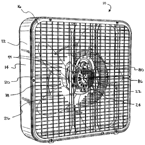
[0017] FIG. l is a perspective view of a fan assembly having a portion of a
rear fan grill
cut away to show an insulator mounting arrangement of an electric motor of the
fan
assembly in accordance with the principles of the present invention.
[0018] FIG. 2 is a perspective view of a motor showing a plurality of
insulating
members mounted thereto, one of the insulating members being shown in exploded
view.
[0019] FIG. 3 is an elevational view of the motor of FIG. 2 mounted to a
portion of a fan
housing with screws, two of the mounting areas being shown in cross-section.
[0020] FIG. 4 is a detailed view of one of the mounting areas shown in FIG. 3.
[0021] FIG. 5 is a partial cross-sectional view of a mounting area having an
alternative
mounting arrangement utilizing an alternative embodiment of an insulating
member.
[0022] FIG. 6 is an assembly view of a motor mount portion of a fan housing
and the
alternative insulating member shown in FIG. 5, the motor mount portion
including a slot
that is configured to cooperate with the insulating member to mount the motor
to the fan
housing.
[0023] FIG. 7 is a partial cross-sectional view of a mounting area having an
alternative
mounting arrangement utilizing an alternative embodiment of an insulating
member.
[0024] FIG. 8 is a plan view of a rear fan grill of the fan assembly shown in
FIG. 1.
[0025] FIG. 9 is a perspective view of a control module for a fan in
accordance with the
principles of the present invention.
[0026] FIG. 10 is a partial elevational view of the control module of FIG: 8
shown
mounted to a fan housing.
[0027] FIG. ll is a partial perspective view of the control module shown in
FIG. 9, with
one case portion of a case of the module being unattached to another case
portian of the
case.


CA 02485236 2004-10-19
6.
Detailed Description of the Preferred Embodiments
[0028] While the present invention will be described folly hereinafter with
reference to
the accompanying drawings, in which one or more particular embodiments is
shown, it is
to be understood at the outset that persons skilled in the art may modify the
embodiments
herein described while still achieving. the desired result of this invention.
Accordingly,
the description which follows is to be understood as an informative disclosure
of one or
more specific embodiments in accordance with the general principles of the
invention
directed to the understanding by persons skilled in the appropriate arts of
those
principles, and not as limitations of the present invention.
[0029] Referring to FIG. 1, an embodiment incorporating the principles of the
present
invention is shown as an electric fan assembly 10. The fan assembly 10
includes a fan
housing 12 having a peripheral shroud portion 14 and two grill portions, a
rear grill
portion 16 and a front grill portion (not shown). In a particular embodiment
suited for
application of the principles of the present invention, the fan housing 12 is
made of a
metallic material and the grill portions are made of a molded plastic
material. Each of
the grill portions are disposed adjacent the shroud portion 14. The shroud
portion 14
together with the grill portions define an interior region 18 of the fan
housing 12 within
which a motorized blade assembly 20 is disposed.
[0030] The motorized blade assembly 20 includes a motor 22 having a motor
casing 24.
In a preferred embodiment, the motor casing 24 is made of a cast metal. As
shown in the
cut away portion of FIG. 1, the motor 22 is mounted to a motor mount portion
of the fan
housing 12. In a preferred embodiment, the motor 22 is mounted to a pair of
mounting
brackets 26 as shown in FIG. 1.
[0031] In accordance with the principles of the present invention, the motor
22 is
mounted to the fan housing 12 in an insulated mounting arrangement. Referring
to FIGS.
2-4, the arrangement includes at least one insulating member 30 connected to a
mounting portion 32 of the motor casing 24. Although the mounting portion 32
is
shown in this embodiment as a portion outwardly and radially extending from
the motor


CA 02485236 2004-10-19
7
casing 32, the mounting portion can be in any form, and integrated with, 'or
separately
attached to, the motor casing 24, as long as the mounting portion 32
facilitates
attachment of the insulating member 30, either directly or indirectly, to the
motor casing
24. In a preferred embodiment, there are four insulating members 30 disposed
about the
motor casing 24 of the motor 22.
[0032] The insulating member 30 preferably includes a base portion 34 having a
mounting surface 36 and a protrusion 38 extending therefrom. The protrusion 38
of the
insulating member 30 is configured to be securely disposed within a mounting
aperture
40 of the motor casing 24, thereby defining a general point of attachment to
the motor
casing 24. Preferably, the protrusion 38 has an interference fit with the
mounting
aperture 40 and is pressed therein by suitable manufacturing methods. However,
the
protrusion 38 can be securely disposed within the mounting aperture by any
number of
means, including by means of adhesive, insertion during casting or molding,
snap fitting
or other mechanical fastening arrangement, weldment, etc. At;cording to a
particular
aspect of the invention, it is preferable that the mounting be facilitated
without the use of
a separate fastener. ,
[0033] As an alternate embodiment, an insulator member can be completely
integrated
within the motor casing, such as by insertion during casting, wherein the
whole insulator
member-in lieu of a protrusion, such as the protrusion 38--could define a
general point
of attachment. In yet another embodiment, a protrusion of the.insulator member
can be
mounted in a radial direction with respect to the motor casing (i.e.,
generally transverse
to an axis defined by a motor shaft S), in lieu of an axial direction as shown
in FIGS. 2
and 3. In such an embodiment, the general point of attachment would be
generally
transverse to a direction of the mounting of the motor casing to the fan
housing (i.e., the
axial direction). In such a case, the mounting of the motor casing to the fan
housing is
still considered as being at the general point of attachment, since the
mounting is
generally positioned within, or adjacent to, a plane in the radial direction
extending
through the point of attachment and the axis of the motor shaft S.


CA 02485236 2004-10-19
8
[0034] If desired, the motor 22 can be supplied as a unit that includes the
insulating
members 30 secured thereto and ready for assembly to the fan housing 12.
[0035] According to a particular aspect of the invention, the general point of
attachment
can serve as a mounting area for mounting the motor casing to the fan housing.
This is
particularly facilitated in embodiments where the insulator member is mounted
to the
motor casing without the use of separate fasteners at the general point of
attachment,
which could otherwise interfere with the mounting of the motor casing to the
fan
housing. In the embodiment shown in FIGS. 1-4, the protrusion 38 of the
insulating
member 30 includes a blind hole 42 configured to accept a screw or fastener 44
(best
shown in FIGS. 3 and 4). Preferably, the fastener is a self tapping or thread-
forming
screw. As shown in FIGS. 3 and 4, the mounting surface 36 of the base portion
34 of the
insulating member 30 is arranged to oppose a mounting surface SO of the fan
housing 12
when the motor 22 is mounted to the fan housing 12 by the fastener 44. The
fastener 44
passes through the mounting surface 50 of the fan housing 12 and penetrates
the base
portion 34 and the protrusion 38 of the insulating member 30. As best shown in
FIG. 4,
the fastener 44 is insulated from the motor casing 24 when the motor is
mounted to the
fan housing 12. The insulating member 30 acts as an electrically insulating
barner
between the fastener 44 and the motor casing 24 as well as between the motor
casing 24
and the fan housing 12. Thus, in the case of a current leakage from the motor
22 that
charges the motor casing 24, the current cannot establish a path to the fan
hpusing 12.
The mounting surface 36 of the base portion 34 is preferably designed to be
large enough
to prevent moisture from completely tracking across the mounting surface 36
and
grounding the motor casing 24 to the fan housing 12.
[0036] According to another aspect of the invention, the insulating member 30
can be
configured to directly engage the motor mount portion of the fan housing 12
without
separate fasteners. In this type of arrangement, the insulating member 30
itself would act
as both a fastener and an insulator between the motor casing 24 and the fan
housing 12.
This arrangement can be achieved through the use of a snap fit with a portion
of the fan


CA 02485236 2004-10-19
s
housing 12, a key fit within an aperture arrangement in the fan housing 12, or
other
suitable arrangement that does not require the use of a separate fastener. In
one particular
embodiment as shown in FIGS. 5 and 6, an insulating member 60 is provided,
which
includes a first base member 62 and a second base member 64 having a neck
portion 66
disposed therebetween. The insulating member 60 also includes a protrusion 68
that
engages the mounting aperture 40 of the motor casing 24. The neck portion 66
is
configured to engage a slot 70 within a motor mount portion 72 of a fan
housing and the
base members 64 and 66 of the insulating member 60 cooperate to engage the
motor
mount portion 72. Numerous other embodiments are contemplated having the
common
feature of avoiding the use of separate fasteners for mounting the motor to
the fan
housing.
j0037] According to another aspect of the invention, insulation between the
motor casing
24 and a portion of a fan housing 73 is facilitated by incorporating one or
more insulating
members 74 that are mounted within an aperture 75 of the portion of the fan
housing 73
as shown in FIG. 7. In this embodiment, the insulating member 74 has a first
portion 76
-defining an insulating portion between the motor casing and the portion of
the fan
housing-and a second portion 77-defining an insulating portion between the
portion of
the fan housing 73 and a fastener 78. In such an embodiment, the fastener 78
can be
allowed to penetrate the motor casing 24 while still being isolated from the
fan housing
73. In a preferred embodiment according to this aspect of the invention, the
insulating
member 74 is a grommet or grommet-like element made of a resilient insulating
material.
[0038] According to yet another aspect of the present invention, the rear
grill portion 16
includes a first mesh portion 80 concentrically disposed about a centrally
disposed first
solid surface portion 81 and a second mesh portion 82 concentrically disposed
about the
first mesh portion 80, as shown in FIG. 8. A second solid surface portion 84
is disposed
therebetween. The mesh portions 80 and 82 are defined by a plurality of
openings within
the rear grill portion 16, as best shown in FIG. 8. The first mesh portion 80
is configured
to be disposed adjacent to a vented rear surface 86 of the motor casing 24 in
the fan


CA 02485236 2004-10-19
assembly, as shown in FIG. 1. The openings of the first mesh portion 80 are
dimensioned such that a user's finger cannot pass therethrough and contact the
motor
casing 24 while still allowing sufficient air flow to cool the motor 22. The
solid surface
portion 84 provides an additional barner between the mounting area and the
user. The
second mesh portion 82 also provides an additional barrier while still
allowing air to flaw
therethrough. These features, alone and in combination, contribute to an
insulating
barner between the motor 22 and the user.
[0039] In fan embodiments that do not incorporate motor assemblies having
controls that
are integrated into the motor casing or disposed adjacent thereto-such as, for
example,
the motor 22 as depicted in FIGS. 1-3, wherein the controls are isolated via
the insulator
members-it may be desirable to separately isolate the controls and associated
electrical
peripherals. Refernng to FIGS. 9-11, a control module 100 having a casing 102
is
depicted, wherein one or more controls and associated electrical peripherals
(such as a
plug receptacle, a light or LED indicator, a fuse holder, associated wiring
and/or wiring
connections, terminals, etc.) of the fan are isolated from surrounding
components that
rnay conduct electrical current to a user, such as a fan housing 103. In the
embodiment
shown, the control casing 102 includes a first casing portion 104 and a second
casing
portion 106. The casing portions may include attachment features in the form
of one or
more snap protrusions 108 and corresponding latch features 110, as shown in
FIGS. 9-11,
which facilitate attachment of the casing portions 104 and 106 to each other.
In this
particular embodiment, the casing portions 104 and 106 include a hinge 111
(shown in
FIG. 11 ) that hingedly connects the casing portions 104 and 106 together.
Preferably, the
hinge is formed from a web of material that is contiguous with the casing
portions 104
and 106. However, the casing portions 104 and 106 could also be completely
separable.
Although this is a preferable attachment arrangement, which could allow
disassembly of
the casing portions if desired, the casing portions could also be permanently
attached to
each other, such as by adhesive, weldment (such as sonic weldment), or other
means. In


CA 02485236 2004-10-19
11
such an embodiment, the control module 100 could be treated as a single drop-
in
replaceable module.
[0040] One or both of the casing portions 104 and 106 may also include an
attachment
feature to facilitate attachment to the fan housing 103, such as one or more
snap
protrusions 112, which engage the fan housing 103 via one or more
corresponding snap
apertures 114 within the fan housing I03. When assembled in a fan assembly,
the casing
102 provides isolation of electrical componentry, which alone or in
combination with
other aspects of the invention described herein, contributes to providing an
insulating
barrier between electrical elements of the fan assembly and the user.
[0041] While one or more specific embodiments have been illustrated and
described,
numerous modifications may come to mind without significantly departing from
the
spirit of the invention, and the scope of protection is only limited by the
scope of the
accompanying Claims.

Representative Drawing
A single figure which represents the drawing illustrating the invention.
Administrative Status

For a clearer understanding of the status of the application/patent presented on this page, the site Disclaimer , as well as the definitions for Patent , Administrative Status , Maintenance Fee  and Payment History  should be consulted.

Administrative Status

Title Date
Forecasted Issue Date Unavailable
(22) Filed 2004-10-19
(41) Open to Public Inspection 2005-04-29
Dead Application 2009-10-19

Abandonment History

Abandonment Date Reason Reinstatement Date
2006-10-19 FAILURE TO PAY APPLICATION MAINTENANCE FEE 2007-10-19
2008-10-20 FAILURE TO PAY APPLICATION MAINTENANCE FEE

Payment History

Fee Type Anniversary Year Due Date Amount Paid Paid Date
Registration of a document - section 124 $100.00 2004-10-19
Application Fee $400.00 2004-10-19
Reinstatement: Failure to Pay Application Maintenance Fees $200.00 2007-10-19
Maintenance Fee - Application - New Act 2 2006-10-19 $100.00 2007-10-19
Maintenance Fee - Application - New Act 3 2007-10-19 $100.00 2007-10-19
Owners on Record

Note: Records showing the ownership history in alphabetical order.

Current Owners on Record
LAKEWOOD ENGINEERING AND MANUFACTURING CO.
Past Owners on Record
ALMANZA, MANUEL
BAIN, BENJAMIN
CHEN, YUNG
Past Owners that do not appear in the "Owners on Record" listing will appear in other documentation within the application.
Documents

To view selected files, please enter reCAPTCHA code :


To view images, click a link in the Document Description column. To download the documents, select one or more checkboxes in the first column and then click the "Download Selected in PDF format (Zip Archive)" or the "Download Selected as Single PDF" button.

List of published and non-published patent-specific documents on the CPD .

If you have any difficulty accessing content, you can call the Client Service Centre at 1-866-997-1936 or send them an e-mail at CIPO Client Service Centre.


Document
Description 
Date
(yyyy-mm-dd) 
Number of pages   Size of Image (KB) 
Abstract 2004-10-19 1 22
Description 2004-10-19 11 566
Claims 2004-10-19 16 573
Drawings 2004-10-19 6 271
Representative Drawing 2005-04-01 1 39
Cover Page 2005-04-12 1 71
Assignment 2004-10-19 8 357
Fees 2007-10-19 2 64