Note: Descriptions are shown in the official language in which they were submitted.
CA 02485272 2004-11-08
WO 03/095040 PCT/CA03/00696
SNOW SKATES
Technical Field
[0001] The invention relates to the field of equipment for descending
S snow-covered slopes, and more particularly to the design and construction
of snow skates.
B ack r~ o
[0002] Conventional snow skis have a length typically greater than 1
1 O meter. Short skis from 60 to 100 cm. referred to as "skiboards", SNOW-
BLADESTT' or Big FootT'r' skis are popular as a novelty for skiers who wish
to retain the skiing experience but with a more easily maneuverable ski.
They tend to be difEcult to control in hard or icy conditions. As well,
skiboards are unstable at speed when ridden flat due to their sidecut.
1 S Further, they do not attempt to emulate the performance of ice skates
which allow a user to both track a straight line or arcs of varying radii,
turn and stop sharply or accelerate on a hard surface.
[0003] Many attempts have been made at designing snow skates
20 which are not much longer than the user's foot. Kinsley United States
Patent no. 1,802,116 discloses a snow skate having a length comparable to
a roller skate for use on snow or ice and having a runner with beaded edges
and a central guide. On snow the skate runs on the full lower surface of the
runner while on ice it rides on the beaded edges. French patent no.
25 1,071,142 issued March 3, 1954 to Henrich discloses a ski from 50 to 65
cm. in length for use on ice-fields, glaciers and the like and having
downwardly projecting metal edges extending along either edge thereof.
Perry United States Patent no. 3,295,859 discloses a metal ski of about
91.5 cm. in length having grooves along the bottom of either lateral edge.
30 United States Patent no. 4,188,046 to Fleckenstein discloses a plastic ski
of
about Slcm. in length with a flat base and no metal edges for use in trick
skiing. Gauer United States Patent no. 4,705,291 discloses a short ski of
CA 02485272 2004-11-08
WO 03/095040 PCT/CA03/00696
-2-
about 80 cm. in length in which the base is substantially convex from front
to rear and from side to side for ease of pivotting and spinning.
[0004] The problem with prior snow skates is that they do not
provide adequate control for the skier on hard or icy surfaces as well as
soft surfaces. There is therefore a need for a pair of snow skates which has
good handling characteristics on such surfaces and can combine the
performance characteristics of ice skates on hard surfaces with the
performance of skis on soft snowy surfaces of varying inclination.
Summary of Invention
[0005] The invention therefore provides a snow skate, comprising an
elongated ski body having an upturned front end and a rear end, the snow
skate comprising: a) an upper surface adapted to receive a boot binding for
releasably securing a boot to the upper surface intermediate said front and
rear ends; b) a base surface having a central generally flat zone and a zone
of increased edge projection forward of the flat zone; c) longitudinal edges
extending along opposed sides of said base surface; wherein the depth of
said edges below said base increases continuously from said flat zone
towards said zone of increased edge projection.
[0006] Preferably the base surface further comprises a second zone
of increased edge projection rearward of the flat zone and the depth of the
edge elements below the base increases continuously from the flat zone
towards the second zone of increased edge projection.
[0007] According to a further aspect of the invention, there is pro-
vided a snow skate, comprising an elongated ski body having an upturned
front end and a rear end, the ski body comprising: a) an upper surface
adapted to receive a boot binding for releasably securing a boot to the
CA 02485272 2004-11-08
WO 03/095040 PCT/CA03/00696
-3-
upper surface intermediate the front and rear ends; b) a base surface having
a central generally flat zone and a zone of increased edge projection
forward of the flat zone ; c) longitudinal edges extending along opposed
sides of the base surface; wherein the transverse concavity of the base
S increases continuously from the flat zone towards the zone of increased
edge projection.
[0008] Preferably, the base surface further comprises a second zone
of increased edge projection rearward of the flat zone and the transverse
1 O concavity of the base increases continuously from the flat zone towards
the
second zone of increased edge projection.
[0009] Preferably, the edges are rockered over the length of the snow
skate.
Brief Description of Drawings
[0010] In drawings which disclose a preferred embodiment of the
invention:
[0011] Fig. 1 is a perspective view of a snow skate according to the
invention;
[0012] Fig. 2 is a perspective view from below of a snow skate
according to the invention;
[0013] Fig. 3 is a lower perspective view of a snow skate according
to the invention;
CA 02485272 2004-11-08
WO 03/095040 PCT/CA03/00696
-4-
[0014] Fig. 4 is a top plan view of a snow skate according to the
invention with lines indicating the cross-sectional contour of
the base at various intervals;
S [0015] Fig. 5 is a side view of a snow skate according to the inven-
tion with a boot mounted thereon and the ski shown in longit-
udinal cross-section, with the degree of rocker exaggerated
for purposes of illustration;
1 O [0016] Fig. 6 is a cross-section taken along lines 6-6 of Fig. 4;
[0017] Fig. 7 is a cross-section taken along lines 7-7 of Fig. 4;
[0018] Fig. 8 is a cross-section taken along lines 8-8 of Fig. 4;
[0019] Fig. 9 is a cross-section taken along lines 9-9 of Fig. 4;
[0020] Fig. 10A-10C are cross-sections of an alternate embodiment
of the invention;
[0021] Fig. 11A-1lE are cross-sections of an alternate embodiment
of the invention;
[0022] Fig. 12A-12F are cross-sections of an alternate embodiment
of the invention;
[0023] Fig. 13A-13F are cross-sections of an alternate embodiment
of the invention;
[0024] Fig. 14- 22 are bottom views and cross-sections of alternate
embodiments of the invention; and
CA 02485272 2004-11-08
WO 03/095040 PCT/CA03/00696
-5-
[0025] Fig. 23 and 24 are bottom views of alternate embodiments of
the invention.
S Description
[0026] Throughout the following description, specific details are set
forth in order to provide a more thorough understanding of the invention.
However, the invention may be practiced without these particulars. In
other instances, well known elements have not been shown or described in
1 O detail to avoid unnecessarily obscuring the invention. Accordingly, the
specification and drawings are to be regarded in an illustrative, rather than
a restrictive, sense.
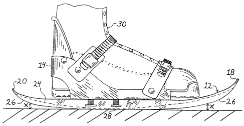
[0027] Figure 1 illustrates one of the snow skates 10 of the invention.
1 S The snow skates are used in pairs, the right and left skates preferably
being
identical. Each snow skate is preferably symmetrical about its central
longitudinal axis. Each snow skate comprises a ski member 12 and a boot
binding 14 which is secured to the upper surface 16 of ski 12 by screws or
other fasteners in the usual way. Preferably two rows of standard snow-
20 board binding 6 mm stainless steel threaded "T"-nut inserts 28, which mate
with the binding's mounting bolts, spaced 4 cm apart are used. Ski 12 has
a forward upturned shovel or tip 18 and rear upturned tip 20, the forward
tip being preferably somewhat higher than the rear tip. The upturned rear
tip 20 permits the ski to go backwards, but need not be upturned if back-
25 wards motion is not required. The ski 12 may have generally vertical side
walls 22 while upper surface 16 is generally flat. The length of ski 12 is
somewhat (a few inches generally) longer than the user's boot at either end,
preferably from about 36 to 51 cm. (14 to 20 inches) with a maximum
length of approximately 25 inches. It is preferably about 13 to 18 cm. (5 to
30 7 inches) in width so that standard snowboard bindings do not extend
beyond the side walls 22. Ski 12 can be slightly narrower for use with ski
CA 02485272 2004-11-08
WO 03/095040 PCT/CA03/00696
-6-
boots; and a smaller (range from 20-4lcm / 8-16" long), narrower (~lOcm /
4" wide) model for children can be provided. Preferably ski 12 has a slight
rocker or reverse camber of the edges from front to rear as described below
in regard to Fig. 4.
[0028] Figures 2 and 3 illustrate the features of the base 24 of ski 12.
Base 24 preferably has generally parallel metal side edges 26. The edges
may converge slightly toward the midline as they upturn at the front and
rear ends 18, 20. Metal edges 26 are standard steel edges having tabs or
1 O holes or other means to fasten or bond them to the construction layers of
the ski. The edges can be mounted vertically rather than horizontally into
the reinforcing fibre cloth/epoxy matrix during construction to allow a
narrow edge apex to be developed. Carbon steel edges are preferred but
other hard metal or synthetic substances which are capable of being
1 S sharpened and holding an edge may also be suitable. Base 24 preferably
has a smoothly varying contour which is generally concave in relation to
the edges 26. Most importantly, as described in more detail below, the
degree of concavity of base 24 is least in the central part of the base 24 and
increases toward either end 18, 20 and most significantly towards the front
20 end 18. Base 24 may have a central convexity 27 or other central feature
to assist in tracking in snow and to assist in bearing the weight of the user
to reduce drag from excessive edge penetration. Other profiles as illus-
trated in Fig. 14 through 19 are also possible to improve straight line
tracking, such as longitudinal grooves, troughs, steps or beads in or on the
25 base surface.
[0029] With reference to Fig. 4 and 5, a boot 30 is shown mounted in
binding 14. The binding 14 is located so that the heel 1 of the user's foot
lies centered approximately in zone C in Fig. 4 and the ball 2 of the user's
3 O foot lies centered approximately in zone B in Fig. 4. As illustrated in
Fig.
5, the base 24 (shown in dotted outline) and edges 26 of ski 12 have a
CA 02485272 2004-11-08
WO 03/095040 PCT/CA03/00696
_7_
slight rocker or reverse camber to allow the ski to sideslip or slidelip or
skid obliquely without biting when the ski is weighted over the flat zone A,
due to the clearance X shown in Fig. 5. The edges 26 may be flat over
length of the flat zone (as shown in Fig. 5 and described below), and then
begin a slight upward curvature at the point of the ball and heel of the foot
towards the front and rear. The slight rocker ahead and behind the foot
arch in combination with the increasing concavity of the base creates a
pronounced curvature of the base surface longitudinally which assists in
carving a turn in snow when the skis are leaned over at speed. The slight
1 O rocker of the snow skates' base edges 26 also allows the snowskater to use
slight shifts in his centre of gravity/balance point to concentrate his weight
preferentially over the central flat zone A of the snow skates, or more
towards the "bite zone" B in a smooth transition, as desired. By having a
slight rocker, the contact surface of the base and edges ahead of and behind
1 S any given bearing point of the sliding surface is lifted just clear of a
hard,
icy surface, and the user is able to employ the varying tracking and holding
characteristics of particular areas of the snow skates' bases on a snow-
covered slope.
20 [0030] Contour lines 32 in Fig. 4 illustrate that the concavity of the base
24 is least in a central flat zone A and greatest towards either end in front
and rear bite zones B and C, and is in transition between minimum and
maximum concavity in transition zones D. Increasing concavity develops
with increasing upturn of the base and edges although the front and rear
25 tips 18, 20 are preferably flat in cross-section. Fig. 6 shows the cross-
section near the center of the flat zone of the preferred embodiment.
Preferably there is a slight concavity side to side even in centre of the flat
zone A, with edges 26 extending to a slightly greater depth than base 24,
so that only edges 26 contact a hard icy surface in the central zone A. Fig.
30 7 shows the cross-section at the edge of the flat zone bordering on the
transition zone. Fig. 8 shows the cross-section where the transition zone
CA 02485272 2004-11-08
WO 03/095040 PCT/CA03/00696
_g_
overlaps the bite zone and Fig. 9 shows the cross-section at the maximum
concavity and resulting bite in the bite zone. As illustrated, the concavity
of the base, that is, the depth of the edges 26 in relation to base 24 in-
creases continuously towards either end of the base 24. In the preferred
S embodiment shown in Fig. 6-9, the slope of the region E of the base
adjacent edge 26, relative to the horizontal, increases from less than 25 or
30 degrees, and preferably less than 10 degrees, in the central region of
the flat zone A to more than 45 degrees and preferably more than 60
degrees in the bite zone B (Fig. 4). Preferably the rear bite zone C has a
1 O lesser degree of bite than the forward zone B, with an angle of slope E
for
example up to 45 degrees. At the same time, the edges 26 in flat zone 5
may project slightly vertically from the plane of base 24 (see Fig. 22B).
Similarly the depth Z of the concave areas of the base 24, relative to the
plane of the edges 26, increases from the flat zone A to the bite zone B.
1 S Depth Z in Fig. 6 may be about 3/16 inches, inceasing to 1/2 inch in Fig.
9.
The range of depth Z in the flat zone A may be from 0 to 1/2 inch and in
bite zone B from 3/8 inches to 1.5 inches. The dotted lines in Fig. 7-9 also
show three variations on how the degree of concavity can be increased in
the forward direction.
[0031] In its simplest embodiment, as shown in Fig. 10A - lOC, the
base 24 can be flat rather than curved or contoured. Fig. 10A is a cross-
section through the center of the flat zone as along lines 6-6 of Fig. 4. Fig.
lOB is a cross-section through the transition zone as along lines 8-8 of Fig.
4 showing increasing projection or depth of edges 26. Fig. 10C is a
cross-section through the bite zone as along lines 9-9 of Fig. 4 showing
maximum projection or depth of edges 26.
[0032] In a further embodiment, as shown in Fig. 11A - 11E, the
base 24 can have a simple curvature which provides a smoother transition
from the base 24 to the edges 26 than in Fig. 10. Fig. 11A is a cross-
CA 02485272 2004-11-08
WO 03/095040 PCT/CA03/00696
-9-
section through the center of the flat zone as along lines 6-6 of Fig. 4. Fig.
11B, 11C and 11D are cross-sections through the transition zone showing
increasing projection or depth of edges 26. Fig. 11E is a cross-section
through the bite zone as along lines 9-9 of Fig. 4 showing maximum
S projection or depth of edges 26 and maximum development of transverse
concavity.
[0033] In a further embodiment, as shown in Fig. 12A - 12F, the base
24 can have a simple curvature similar to that in Fig. 11 which provides a
1 O smoother transition from the base 24 to the edges 26 than in Fig. 10 and
wherein the forward transverse concavity and forward projection or depth
of the edges is greater than in the rear bite zone. Fig. 12D is a cross-
section through the center of the flat zone as along lines 6-6 of Fig. 4. Fig.
12B and 12C are cross-sections through the forward transition zone
1 S showing increasing angle of slope E and projection or depth of edges 26.
Fig. 12A is a cross-section through the forward bite zone as along rightmo-
st lines 9-9 of Fig. 4 showing maximum projection or depth of edges 26.
Fig. 12E is a cross-section through the rear transition zone showing rela-
tively lesser increasing projection or depth of edges 26 and lesser increasi-
20 ng concavity than the forward bite zone. Fig. 12F is a cross-section
through the rear bite zone as along leftmost lines 9-9 of Fig. 4.
[0034] In a further embodiment, as shown in Fig. 13A - 13F, the
25 edges 26 can follow the increasing curvature of base 24. Fig. 13A is a
cross-section through the center of the flat zone as along lines 6-6 of Fig.
4, with a flat portion 29 to receive the binding 14 . Fig. 13B - 13E are
cross-sections through the transition zone showing increasing concavity
and projection or depth of edges 26 due to increased deflection and
30 curvature of base 24. Fig. 13E is a cross-section through the bite zone as
along lines 9-9 of Fig. 4 showing maximum concavity and projection or
CA 02485272 2004-11-08
WO 03/095040 PCT/CA03/00696
- 1~ -
depth of edges 26. Alternatively, the increasing exposure of the edges
compared to the base can be achieved by increasing the angle of the edges
26 from the horizontal, while the edges remain aligned with the base,
either with edges which are straight or curved in cross-section. For exam-
S ple the area in slope E could have an increasing curvature in cross-section
towards the bite zone. Fig. 13A-13E also show an embodiment whgere the
edges 26 are formed from the same material as the body of the ski 12, such
as injected molded plastic. Fig. 13F shows a steel edge insert 26. Fig. 13E
shows raised flanges 17 which could be provided to receive a boot binding
1 O other than a standard snowboard binding.
[0035] While the invention will work also if the increase in conca-
vity, projection or depth of the edges or effective "bite" of the base is only
present forward of the central flat zone, it is preferred to have this
increase
15 in base concavity, projection or depth of the edges in both forward and
rearward directions. This avoids a tendency to pivot and generally pro-
vides better tracking and greater control for the user.
[0036] Fig. 14 through 24 show alternative profiles for base 24 in
20 bottom views and cross-sections. In Fig. 14, Fig. 14A is a cross-section
along lines J-J and Fig. 14B shows five different cross-sections along lines
K-K wherein steps or slots are provided to enhance tracking. Fig. 14A
shows a wood core central section 77 in combination with a fibre compos-
ite sidewall 79. In Fig. 15, two possible cross-sections along lines L-L are
25 shown in Fig. 15A, showing single-step and double-stepped edges and Fig.
15 B shows a central groove or multiple grooves in the flat zone taken in
cross-section along line M-M. In Fig. 16, the cross-section along lines N-
N is shown in Fig. 16A, the cross-section along lines O-O is shown in Fig.
16B, which has a central convexity and bead or multiple tracking beads,
30 and the cross-section along lines P-P is shown in Fig. 16C whereby a keel
can be developed from diminishing central convexity. In Fig. 17, the
CA 02485272 2004-11-08
WO 03/095040 PCT/CA03/00696
-11-
cross-section along lines Q-Q is shown in Fig. 17A, the cross-section
along lines R-R is shown in Fig. 17B, and the cross-section along lines S-
S is shown in Fig. 17C, whereby a central planar area in the flat zone
diminishes to provide the increased concavity and projection of the edges
in the forward direction. The dotted lines in Fig. 17A show a central keel
which may be developed. In Fig. 18, the cross-section along lines T-T is
shown in Fig.l8A, the cross-section along lines U-U is shown in Fig. 18B,
and the cross-section along lines V-V is shown in Fig. 18C, whereby a
central flat runner diminishes in width to provide a rear keel 88 for track-
1 O ing and extra bite. Fig. 18A shows a top structural sheet 80, honeycomb
core 82, base structural sheet 84, P-tex base 86 and edge 26. In Fig. 19,
the cross-section along lines a-a is shown in Fig. 19A, the cross-section
along lines b-b is shown in Fig. 19B, the cross-section along lines c-c is
shown in Fig. 19C, and the cross-section along lines d-d is shown in Fig.
19D, whereby a central V-shaped runner diminishes towards the front and
rear as a narrowing keel. In Fig. 20, the cross-section along lines e-a is
shown in Fig. 20 A, the cross-section along lines f-f is shown in Fig. 20 B,
the cross-section along lines g-g is shown in Fig. 20 C, and the cross-
section along lines h-h is shown in Fig. 20 D, wherein a deeply relieved
front and rear concavity becomes confined as a shallower, narrower central
trough through the flat zone. In Fig. 21, the cross-section along lines i-i is
shown in Fig. 21 A, the cross-section along lines j j is shown in Fig. 21 B,
the cross-section along lines k-k is shown in Fig. 21 C, and the cross-
section along lines 1-1 is shown in Fig. 21 D, wherein the side edges
develop into a base surface and a deeply relieved front and rear concavity
becomes confined as a shallower, narrow central trough through the flat
zone. The dotted lines show an alternative base configuration. In Fig. 22,
the cross-section along lines m-m is shown in Fig. 22 A, the cross-section
along lines n-n is shown in Fig. 22 B, and the cross-section along lines o-o
is shown in Fig. 22 C, which illustrates how the slope E in the flat zone
immediately adjacent the edges 26 may be great in some embodiments
CA 02485272 2004-11-08
WO 03/095040 PCT/CA03/00696
- 12-
where the edges in that region project only slightly from base 24, and also
shows a lesser degree of edge prominence and transverse concavity in the
rear bite zone than in the forward bite zone. Fig. 23 illustrates an embodi-
ment having straight parallel edges 26 with no convergence at the front tip.
S Fig. 24 illustrates a discontinuity 50 in side edges 26 and concavity 52
which acts as a grind-plate to permit skaters to balance and slide sideways
while riding along a rail or paired rail as provided in terrain parks.
[0037] The snow skate ski 12 of the invention can be manufactured
1 O using modified existing snowboard/ski manufacturing methods and materi
als. For use on ski hills, it is preferable to produce the snow skate as a
steel-edged, strong, lightweight construction able to mount to most snow-
board bindings. Steam-bent, laminated wood strips (e.g. ash), drilled to
accept stainless steel T-nut snowboard binding inserts in the standard
1 S 4x4cm pattern, can be used to make the core of the snow skate; this can
then be milled to shape for fixing/bonding the carbon steel edge strips, the
core then covered/wrapped by reinforcing fiberglass cloth layers in an
epoxy resin matrix; a protective cosmetic topsheet and a low-friction base
surface layer. Manufacturing processes such as matched die
20 heat/compression moulding, or resin transfer moulding may be used;
synthetic fiber (e.g. fiberglass; carbon fiber; KevlarTM) cloth and epoxy, or
epoxy pre-preg layers, can be used in the lay-up over a central core of
laminated wood strips or a honeycomb material as in a structural sandwich
construction; a moulded rim construction, involving injecting a suitable
25 synthetic resin around a wood core, may also be used as illustrated in Fig.
14A; an exothermically expanded foaming synthetic resin such as polyure-
thane possibly strengthened by internal wood or other synthetic stringers
centrally can also provide the stiff central core of the snow skate encased
by the reinforcing sheet layers, as with a modified cap construction; the
30 laminate may further comprise an elastomer-layer, a layers) of spring steel
or titanium or other suitable metal or alloy; and other advanced composites
CA 02485272 2004-11-08
WO 03/095040 PCT/CA03/00696
-13-
and engineered polymeric thermoset or thermoplastic resins could as well
be used to make up ski 12, in whole or in part [see fig. 14A]. A drilled or
punched reinforcing sheet or plate of a suitable rigid material, to receive
the T-nut inserts and further prevent them from being ripped out under
stress, can also be added during the lay-up. Among others known in the art,
some suitable low-friction base surface materials, finishes, or treatments
for the snow skate are: Ultra High Molecular Weight Polyethylene
(UHMWPE); sintered P-TexTM; heat-melted fusable powdered polyethyl-
ene; polyurethane; ABS. A suitable thermoplastic (e.g. polyethylene;
1 O ABS) or fiber-reinforced thermoplastic or alloy may rather be used via
extrusion blow moulding or injection moulding as for making a child's
version of the snow skate, or otherwise for a version intended for use on
snowy ground apart from ski hills; attached plastic rachet-type buckles or
nylon strap/VelcroTM bindings can be used for such a toy model of ski 12
with a suitable heelstop on the top surface of ski for securing binding
around the ankle. The snow skates should be stiff centrally, yet become
slightly flexible forward of the balls of feet (and back of heels) to gain a
mechanical advantage of spring/recoil when pushing off the bite zone
forwardly on the snowy ground in skating, and for shock absorption while
in motion and during hard braking. Flex characteristics can be effected by
making the snow skate thicker centrally and thinner towards the front and
rear shovel portions, as for a structural sandwich construction having a
core of diminishing thickness towards the ends of the laminate; shock
absorption can be furthered by the use of elastomeric sheet layers in the
construction of ski 12. While the downturned slope region E of the bite
zones) inherently stiffens the structure, the use of more pliant laminates or
materials laterally [see fig. 14A], and the use of segmented edge strips, can
better allow ski 12 to flex slightly towards the front and rear of the snow
skate. A slight rocker is desirable over the length of the snow skate from
the bite zones) towards the flat zone.
CA 02485272 2004-11-08
WO 03/095040 PCT/CA03/00696
- 14-
[0038] In another embodiment, the snow skates could be made using
two sheets of steel or other suitable metal (e.g. aluminum; titanium) or
alloy stamped out or otherwise formed to shape, or advanced composite
pre-pregs or fiber-reinforced thermoplastic sheets or another suitably
formable sheet material could be heat/compression moulded or vacuum
moulded to form the top and base surfaces; the top and bottom surfaces
can then be welded, tightly bonded, or otherwise fastened together to form
the ski 12 of the invention. Exothermically expanded polyurethane foam/a
foaming synthetic resin can be injected, or a similarly suitable core filler
1 O can be used, to solidify the gaps between the flat upper surface and the
complex curvature of the base surface sheet or otherwise between the
laminated layers of the construction. A drilled or punched reinforcing sheet
or plate of a suitable rigid material, to receive the T-nut inserts and
further
prevent them from being ripped out under stress, can also be added during
the construction.
[0039] In another embodiment, a single structural sheet of steel or
other suitable material can be stamp-moulded, or otherwise shaped to form
the increasingly narrow and exposed and vertical side edges fore and
rearward of the central flat zone. Once the stainless steel T-nut inserts for
mounting snowboard bindings are in place in drilled/punched holes of the
sheet, a molded base surface of suitable thermoplastic/ thermoset material
can be joined to the sheet so as to form the base surface shape, and then
covered with, or else already having, a suitable ultralow-friction base
surface for sliding; or a resilient. hard material can be joined to the sheet
to
develop the base to edge transition, as shown in Fig. 21. In another
embodiment, a sheet of structural steel or other suitable rigid material can
be stamped or molded to form the shape of the base surface and side edge
profile, then a top sheet or layer of suitable material can be fixed to it
overtop the positioned threaded T-nut binding inserts 28, so as to provide a
smooth, even top surface for the snow skates. In yet another embodiment,
CA 02485272 2004-11-08
WO 03/095040 PCT/CA03/00696
-15-
a single sheet of steel or other metal or alloy, or a similarly suitable mate-
rial layer, can be formed to make up the general shape of the snow skate;
exposed at the downturned side edges, the steel sheet can be embedded in a
suitable polymeric plastic moulded around it to provide the top and the
S specific base contour of ski 12 [see fig. 14B], having had the T-nut inserts
positioned in holes made in the sheet prior to the moulding operation. Ski
12 could also be fashioned from a single piece of spring steel, or other
suitable metal or alloy, having drilled and tapped holes to receive a boot
binding, and having a low friction surface treatment, layer, or coating
1 O applied to the base of the snow skate, and a cosmetic finish layer,
coating,
or treatment applied to the top of the ski.
[0040] In further embodiments, a simple rockered base, which is
generally flat (and may be slightly concave) from side to side, can be given
1 S the varying degree of edge projection necessary for the invention by
varying the width of the mounted side edges; or varying the mounting
position of an edge strip of a given width; or varying the angle at which the
side edge strips are mounted; or the snow skates' thickness can be varied
using side edge strips of a given width to achieve the edge prominence
2~ required for varying degrees of bite into the snow; or a combination of the
above. Such side edge strips can further vary in the angle at which they
are mounted in the bite zone, from a vertical orientation down to 45
degrees, and still provide adequate bite into the snow to thereby provide
the required degree of vertical edge penetration into the snowy ground,
25 relative to the resting base surface contour along the length of the skate,
to
perform as desired by the user.
[0041] The vertical or otherwise inclined steel edges may be screw-
ed, laminated, or tightly bonded to the snow skates, or joined as an insert
30 during an exothermic thermoset/advanced composites/engineered resin
molding process. The edges could also be suitably made from inset,
CA 02485272 2004-11-08
WO 03/095040 PCT/CA03/00696
-16-
resilient, hardened material forming the side walls 22 and/or running
edges of the base surface (shown in Fig. 21); the inset material being
capable of being sharpened and holding an edge, for example Nylon or
Polycarbonate plastic [Delrin~"'']. The steel edges 26 should preferably
approach being level with the bottom of base 24 at the flat zone, or project
slightly below the level of base 24 to give a generally slightly concave or
concave-convex-concave base surface in cross-section at the middle of the
flat zone.
1 O [0042] Thus concentrating the weight of the user more towards the
central flat zone of the base permits side slippage, pivoting, spinning or
turning backwards. Concentrating the weight of the user on the front (or
rear) bite zones allows the user to carve turns, brake, stop or perform a
skating motion in which the user alternately forces off the inside edge of
1 S each ski in the area of the bite zone to obtain acceleration. Stopping can
be
achieved either using a sideways hockey stop or snowplow motion while
going forwards or a reverse snowplow going backwards.
20 [0043] As will be apparent to those skilled in the art in the light of
the foregoing disclosure, many alterations and modifications are possible
in the practice of this invention without departing from the spirit or scope
thereof. For example, features of specific variants shown in the drawings
may be combined with specific features of other variants to produce a
25 snow skate with the desired combination of sideslipping and biting
characteristics. Accordingly, the scope of the invention is to be construed
in accordance with the substance defined by the following claims.