Note: Descriptions are shown in the official language in which they were submitted.
CA 02485401 2005-01-11
1
A BEVERAGE VENDING MACHINE INSTALLATION
The present invention relates to a beverage vending
machine installation of the type commonly used, for example,
for dispensing coffee and tea beverages.
Vending machines for dispensing beverages such as
coffee are well-known in the art. Typically, such vending
machines allow for delivery of beverages in a `self-service'
mode of operation where a customer operates the vending
machine without direct external supervision. Vending
machines of this type may be provided as a stand-alone item
situated on a worktop, bench or similar. Alternatively,
where the vending machine is to be used in a public place as
opposed to a private setting, it is known to locate the
vending machine within a cabinet to form a vending machine
installation. Typical locations for such vending machine
installations include service stations and the communal
areas of public buildings such as theatres, gymnasiums,
cinemas, etc. The cabinet in which the vending machine is
installed serves to provide a secure means of housing the
vending machine to prevent unauthorised operation or access
to parts of the vending machine not required for direct
operation. In addition, the cabinet may provide sites for
advertising and instructions for operation of the machine to
be displayed. In known vending machine installations,
access to the vending machine within the cabinet is provided
by a rear-facing opening in the cabinet, that is, on the
side of the cabinet opposed to the side at which the
customer operates the vending machine. Opening the cabinet
from the rear has in the past been necessary to allow access
to the vending machine for repair and maintenance since a
CA 02485401 2005-01-11
2
number of the components of the vending machine are
inaccessible from the front side. It is preferable to
situate the cabinet against a wall or similar structure to
minimise the space taken up by the installation within the
room, foyer, etc. A problem with known vending machine
installations is that locating the installation in this way
makes ready access to the rear of the cabinet difficult.
Typically, this is solved by providing a room, corridor or
similar space behind the wall against which the vending
machine installation is located. Access is then obtained
through an aperture in the wall. A disadvantage of this
solution is that extra floor space is taken up by the room
or corridor behind the cabinet.
It is well-known to try and make the dimensions of the
vending machine installation as small as possible to allow
the installation to be located in smaller establishments.
However, this has a disadvantage that the vending machine
and its associated equipment within the cabinet can be
difficult to access for maintenance purposes, even where the
cabinet is accessed from the rear. In particular, portions
of the vending machine and ancillary equipment located on
the lateral sides of the units are difficult to access due
to the close proximity of other equipment and walls within
the cabinet.
According to the present invention, there is provided a
beverage vending machine installation comprising a cabinet
and a trolley unit, the cabinet defining a void in which, in
use, the trolley unit can be positioned, the cabinet further
comprising an opening and at least one door moveable between
open and closed positions, the trolley unit comprising a
beverage vending machine, the trolley unit being moveable
CA 02485401 2005-01-11
3
relative to the cabinet between an installed position, in
which the trolley unit is positioned within the void of the
cabinet such that the at least one door may be closed to
allow operation of the beverage vending machine
installation, and an uninstalled position, in which the
trolley unit is removed from the cabinet after opening the
at least one door to allow access to the trolley unit.
Advantageously, the beverage vending machine installation
of the present invention may be installed in a wide variety
of locations since no access is required to the rear of the
cabinet either in use or during maintenance procedures. As
a result, the vending machine installation may be installed
hard up against a solid wall and there is no requirement to
provide a room or other void space directly behind the
cabinet. Thus, floor space is saved. Further, providing
the vending machine on a trolley unit which may be
uninstalled from the cabinet advantageously allows for much
easier access to the components of the vending machine to
carry out maintenance procedures. In addition, locating the
vending machine on a trolley unit allows different vending
machine assemblies to be quickly and easily swapped in and
out of a single cabinet. For example, a defective vending
machine may be easily removed and replaced with a working
vending machine allowing the vending machine installation to
be used by customers whilst the defective machine is
repaired away from the installation.
Preferably, the opening of the cabinet is at a front face
of the cabinet. The door of the cabinet may comprise upper
and lower portions. The upper and lower door portions may be
portions of a single door. The upper and lower doors may be
opened independently of one another or may be moved as a
CA 02485401 2005-01-11
4
single door. Parts and components requiring regular
maintenance may be positioned behind the lower door such
that the upper door need be opened less frequently. With the
upper and lower doors closed, an aperture may be defined
through which a user can operate the vending machine.
Preferably, the trolley unit comprises castors to allow
the trolley unit to be rolled between the installed and
uninstalled positions.
Preferably, the trolley unit comprises a load-bearing
framework. The framework preferably comprises one or more
guide bars and the cabinet comprises a guide frame, wherein
on movement of the trolley unit from the uninstalled
position into the installed position the guide bars and
guide frame interact to locate the trolley unit relative to
the cabinet. The interaction between the guide frame and the
trolley framework ensures that the trolley unit is
accurately and positively located when installed within the
cabinet. It also makes the installation process simpler by
allowing the installer to simply push the trolley unit
inwards; the lateral location of the trolley unit is
controlled by the guide frame.
Preferably, the trolley unit comprises a handle rotatably
moveable from a vertical, stowed position and an in-use
position.
Preferably, the cabinet comprises one or more ports for
the conveyance of utilities and the trolley comprises one or
more sockets for the reception of utilities wherein the
ports and sockets are connectable in use by means of one or
more conduits. The utilities may comprise one or more
utilities selected from the group of electricity, telephone
and mains water. A particular advantage of the present
CA 02485401 2005-01-11
installation is that the trolley unit and cabinet and only a
small number of connections therebetween. In one embodiment
the cabinet and trolley unit are connected. only by a mains
water conduit and a mains electricity cable. Both
5 connections may be provided with bayonet fittings, plugs or
similar to allow the connections to be quickly and easily
made and broken. This allows the trolley unit to be very
quickly installed and removed from the cabinet.
The beverage preparation machine prepares and dispenses
one or more beverages typically selected from the group of
roast and ground coffee, tea, soup, chocolate, carbonated
beverages or water. Other beverages may be dispensed as
required.
The vending machine may be provided with storage
containers, such as hoppers, for storing beverage
preparation ingredients, which containers are arranged to
supply the beverage preparation machine with a supply of
beverage ingredient. Further, the cabinet may be provided
with larger beverage storage containers so as to provide
more beverages before refilling is needed. The beverage
storage containers are, preferably, provided with apparatus
for determining when the container is nearly empty and/or
entirely empty.
The trolley unit may comprise an upper platform for
supporting the beverage vending machine. Preferably, the
trolley unit comprises a lower platform.
Preferably, the trolley unit comprises a refrigerator
unit. Preferably, the refrigerator unit is positioned on the
lower platform. Preferably, the refrigerator unit is
accessible by opening the at least one door of the cabinet.
The trolley unit may comprise one or more cup holders.
CA 02485401 2005-01-11
6
The trolley unit may comprise one or more waste
receptacles.
Preferably, the trolley unit comprises one or more
mounting assemblies for ancillary equipment. Preferably, the
one or more mounting assemblies are pivotable about a
vertical axis. Preferably, the one or more mounting
assemblies are pivotable from a first position, in which the
mounting assemblies lie in close proximity with the at least
one beverage preparation machine, and a second position, in
which the mounting assemblies are rotated away from the at
least one beverage preparation machine to allow access to
all sides of the at least one beverage preparation machine
and the ancillary equipment. Preferably, the at least one
mounting assemblies comprise a horizontal platform mounted
for rotation about a vertical support post, the vertical
support post being mounted to the upper platform of the
trolley unit. In addition, the horizontal platform may be
slidable along an axis perpendicular to the vertical support
post from a retracted position, in which the horizontal
platform lies in proximity to the vertical support post, and
an extended position, in which the horizontal platform is
extended away from the vertical support post.
The ancillary equipment may comprise one or more items of
equipment selected from the group comprising a beverage
preparation machine, a refrigerator, a payment unit, a
filtration unit - which is provided to filter water and
ensure ongoing serviceability of the vending machine, a
power supply unit or a waste receptacle unit.
Preferably, the cabinet comprises one or more ancillary
doors moveable between a closed position, in which the
ancillary equipment is shielded from access by a user of the
CA 02485401 2005-01-11
7
vending installation, and an open position, in which the
ancillary equipment may be accessed.
The beverage vending machine installation may, in a
particularly preferred embodiment, comprise the at least one
beverage preparation machine and a secondary beverage
preparation machine mounted as an item of ancillary
equipment.
The present invention also provides a beverage vending
machine installation comprising a primary :beverage
preparation machine, a secondary beverage preparation
machine, a customer interface, a telemetry device, and a
system controller, wherein the system controller monitors
and controls operation of the primary and secondary beverage
preparation machines, the customer interface and the
telemetry device, wherein the system controller further
collates operational information from the primary and
secondary beverage preparation machines and transmits said
data to a secure site using the telemetry device.
Advantageously, the single system controller collates and
transmits data to the secure site for multiple elements of
the installation. This allows equipment to be easily added
or removed or interchanged within the installation without
requiring additional telemetry devices to be fitted.
The system controller may comprise an interlock mechanism
for preventing simultaneous operation of the primary and
secondary beverage preparation machines.
The system controller may be operable to control the type,
quantity and sequence of beverage ingredients delivered by
the primary and secondary beverage preparation machines.
The primary and secondary beverage preparation machines
may dispense at a single dispense point.
CA 02485401 2005-01-11
8
Preferably, the system controller is operable to monitor
the status of the primary and secondary beverage preparation
machines and in particular, quantities of beverage
ingredients contained in said primary and secondary beverage
preparation machines, and further is operable to exclude
dispensation of beverage types where suitable beverage
ingredients are not available.
In a preferred embodiment the system controller is
operable to manage cleaning of the primary and secondary
beverage vending machines. The system controller may be
operable to notify an operator that cleaning of one or more
beverage preparation machine is required. The system
controller may be operable to shut down operation of the
installation where cleaning is not undertaken within a
predetermined time span or cleaning is initiated without
inputting an authorisation code into the customer interface.
Preferably, the system controller is operable to display
cleaning instructions to the operator using the customer
interface.
An embodiment of the present invention will now be
described, by way of example only, with reference to the
accompanying drawings in which:-
Figure 1 is a perspective view of a trolley frame of a
trolley unit of a beverage vending machine installation of
the present invention;
Figure 2 is a perspective view of the trolley frame of
Figure 1 with a handle of the trolley frame in a lowered
configuration;
CA 02485401 2005-01-11
9
Figure 3 is a perspective view of the trolley frame of
Figure 1 having mounted thereon an upper surface and a
refrigerator;
Figure 4 is a perspective view of the trolley frame of
Figure 3 having a beverage preparation machine and ancillary
units mounted thereon to form a trolley unit, the ancillary
units being in a first position;
Figure 5 is a perspective view of the trolley unit of
Figure 4 showing the ancillary units in a second position;
Figure 6 is a perspective view of a cabinet of the
vending machine installation of the present invention with a
door of the cabinet in an open position;
Figure 7 is a perspective view of the trolley unit of
Figure 4 and the cabinet of Figure 6 in combination; and
Figure 8 of the vending machine installation ready for
operation.
As shown in Figures 7 and 8, the beverage vending
machine installation of the present invention generally
comprises a trolley unit 1 which is removably installed in a
cabinet 12. Referring to Figure 6, the cabinet 12 comprises
a housing 13 with a generally parallelepiped shape having an
upper wall 13a, a lower wall 13b, two side walls 13c, a rear
panel 13d and two doors 14, 15. The housing 13 is provided
with an internal structural framework 18 of metal bars
providing structural integrity and cross-bracing to the
housing 13. A front face 13e of the housing 13 is open and,
in use, is closed by the two doors 14, 15. The two doors
14, 15 form an upper door 14 and a lower door 15. The upper
door 14 and lower door 15 are connected by a hinge 60 to the
housing 13 and can be moved independently of one another
CA 02485401 2005-01-11
between open and closed positions. Alternatively, the doors
14, 15 may be joined to move effectively as a single door.
One or more locks may be provided on both the upper and
lower doors 14, 15 to secure the doors in the closed
5 position. As shown in Figure 8, the upper door 14 and lower
door 15 when in the closed position do not obscure the
entire area of front face 13e. Instead, with the upper door
14 and lower door 15 in the closed positions, an aperture 19
is defined to allow a customer access to a vending machine
10 installed within the cabinet 12 as will be described below.
Advantageously, the cabinet 12 provides secure containment
of the trolley unit 1 and may be secured to the floor or a
near-standing wall for added security by means of bolts, for
example.
Left and right ancillary unit doors 16, 17 are provided
hinged to the cabinet 12, the use of which will be described
below. The ancillary unit doors may be separate from the
upper and lower doors 14, 15 or may be fixed thereto so as
to move together with the upper and/or lower doors 14, 15.
In the illustrated embodiment, the left ancillary door 16 is
affixed to the upper door 14 whilst the right ancillary door
17 is separate from the upper and lower doors 14, 15.
A base region of the framework 18 of the cabinet 12 is
provided with a guide frame 45 which comprises a plurality
of metal members formed to provide a stable base for the
cabinet 12. In addition, the guide frame 45 comprises a
pair of angled guide bars 46 at either side of the cabinet
12. The four guide bars 46 define a mouth 47 of the guide
frame 45 which is directed towards the open front face 13e
of the housing 13. The pairs of guide bars 46 are angled
towards one another as one moves towards the rear panel 13d
CA 02485401 2005-01-11
11
of the housing 13 such that the clearance between the pairs
of guide bars 46 narrows as one moves into the cabinet 12
from the front face 13e. The use of the guide bars 46 will
be described below.
The structural frame 18 of the cabinet 12 may be made
from a suitable material such as steel. Preferably, the
members are welded together for maximum structural strength.
However, other fixing means such as bolts or other
releasable fasteners may be used.
The upper wall 13a, lower wall 13b, side walls 13c,
rear panel 13d and doors 14,. 15, 16 and 17 may be formed
from suitable material such as sheet metal or plastics
materials. The walls may be mounted to the framework 18 by
known means such as rivets or releasable fasteners, e.g.
bolts, clips, etc. Light fittings, advertising place
holders, etc., may be mounted on the cabinet 12 in a known
manner. The cabinet 12 is provided with one or more
apertures (not shown) through which mains water pipes and
electricity cables can be passed to allow the vending
machine located within the cabinet 12 to be plumbed into the
water and electricity supplies.
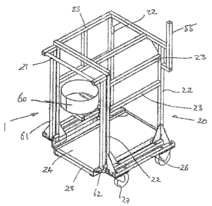
As shown in Figure 1, the trolley unit 1 comprises a
trolley frame 20 on which is mounted the vending machine.
The trolley.frame 20 has a generally parallelepiped form
comprising vertical upright members 22, crossbars 23 and a
basal framework 25. A lower platform 24 is mounted on the
basal framework 25, the use of which will be described
below. A handle is provided for moving the trolley
framework 20. The handle comprises a cross-bar 21 which is
rotationally mounted to the trolley frame 20 by means of two
struts 61 which are mounted to the trolley frame 20 at a
CA 02485401 2005-01-11
12
lower end at hinge points 62. The handle can be rotated from
a stowed position as shown in Figure 1 in which the struts
61 are vertical to a in-use position, as shown in Figure 2,
in which the handle is rotated away from the trolley frame
20 to allow access to the cross-bar 21. The trolley frame 20
is moved by grasping the cross-bar 21. The trolley framework
20 is provided with four casters 27 to allow the trolley
unit 1 to be easily moved by rolling on a hard surface such
as a floor. The basal framework 25 comprises a rectangular
arrangement of structural members and, in addition, a pair
of guide extension members 26 located one on each side of
the trolley framework 20. The use of the extension guide
members 26 will be described below. Optionally, the trolley
frame 20 may not have a handle but instead be manoeuvred by
grasping the frame 20 itself.
The trolley frame 20 also comprises a metal hoop 60 for
retaining a water filter which may form part of the vending
machine installation if required. The frame 20 also
comprises a metal upright support post 55, the use of which
will be described below.
As shown in Figure 3, a refrigerator 3 is positioned in
use within the trolley framework 20 resting on the lower
platform 24. The refrigerator 3 comprises a housing 31 with
a front-facing hinged door 30 which can be opened and shut
whilst the refrigerator 3 is positioned within the trolley
framework 20. The refrigerator 3 may be used to hold items
requiring refrigeration. In particular milk for use in
preparing beverages is stored in the refrigerator.
Preferably, the milk is stored in pre-filled cartons. The
capacity of the refrigerator is preferably large enough to
hold at least two cartons of milk so that one carton can
CA 02485401 2005-01-11
13
provide a back-up supply. Preferably, a piped connection is
made from the carton of milk in the refrigerator upwards to
the vending machine located on the trolley unit 1. The flow
of milk along the piped connection may be driven by means of
a pump or by means of a pressure drop produced by the
vending machine at the remote end of the piped connection.
Typically, a venturii flow in the vending machine may be
used to produce the required pressure drop.
Also with reference to Figure 3, the trolley unit 1 is
provided with an upper platform 2 forming a support surface
for the vending machine components. A number of apertures
are provided within the upper platform 2, the use of which
will now be described.
As most clearly shown in Figure 3, the trolley unit 1
comprises two cup holders 5 which are accessed through two
apertures 35 in the upper platform 2. The cup holders 5 are
used to hold cups or similar containers ready for use by a
customer. Further, the two cup holders may hold cups of
different sizes.
A cash box 6 is mounted to the trolley unit 1 and
accessed through a cash box aperture (not shown) in the
upper platform 2 which is linked to a chute (not shown)
which extends from the aperture to the cash box 6. The cash
box 6 may further comprise a credit card slot and credit
card reader to facilitate processing of credit card
payments.
A waste bin 4 is mounted to the under surface of the
upper platform 2. A first waste bin aperture 36 is provided
in the upper platform 2 through which waste materials from
the vending machine situated on top of the upper platform 2
may be dispensed into the waste bin 4. A secondary aperture
CA 02485401 2005-01-11
14
37 is provided for use by customers for manually disposing
of unwanted items such as spent cups and napkins. The
secondary aperture 37 also discharges into the waste bin 4.
A liquid waste bin 8 is also provided for liquid waste
products from the vending machine. In addition, liquid
waste may be expelled, via appropriate pipework to mains
drainage. Other apertures may be provided in the upper
platform 2 as required. For example, apertures 38 and 39 as
shown in Figure 3 are provided for allowing passage of
cabling or pipework from below the upper platform 2 to the
vending machine when mounted on the upper platform 2.
As shown in Figure 4, the vending machine is mounted on
the trolley frame 20. The vending machine comprises a number
of component parts which cooperate together to dispense
beverages and other items as directed by a customer. Central
to the vending machine is a primary beverage preparation
machine 9, which in this embodiment is shown in the form of
a coffee brewer., The primary beverage preparation machine 9
is located centrally on the upper platform 2. The primary
beverage preparation machine may be positively located
against a C-shaped locating bracket 50 affixed to the upper
surface of the upper platform 2 as shown in Figure 3. The
primary beverage preparation machine 9 may be of a known
type and typically will comprise a source of roast and
ground coffee - e.g. in the form of a hopper or similar, a
water heater, a pump, connectors for connecting the primary
beverage preparation machine 9 to electricity and mains
water supplies, a steam generator and one or more dispensing
outlets through which the prepared beverage is dispensed
into a receptacle. The primary beverage preparation machine
9 may be bolted to the upper platform 2 or may be retained
CA 02485401 2005-01-11
simply by action of its own weight. The primary beverage
preparation machine 9 may be designed to dispense only a
single beverage or to dispense a range of beverages.
As shown in Figure 4, one or more pieces of ancillary
5 equipment are located to either side of the primary beverage
preparation machine 9. In the illustrated embodiment two
ancillary equipment units 10, 11 are mounted on pivotal
stands 51. Figure 4 shows the ancillary equipment units 10,
11 in a first position in which the ancillary equipment
10 units 10, 11 face forwards and are parallel to the side
walls of the beverage preparation machine 9 so that they lie
in close proximity to the side wall of the primary beverage
preparation machine 9. The stands 51 each comprise a
horizontal platform 53 on which the ancillary equipment is
15 mounted, either in fixed or free-standing manner. One of the
platforms 53 is pivotally mounted to the support post 55 of
the trolley frame 20 which extends upwardly from the upper
platform 2. The other platform 53 is mounted directly to the
upper platform 2. As such, the ancillary equipment may be
rotated relative to the upper platform 2 by rotational
movement of the platforms 53 about the support post 55 or
upper platform 2. In addition, preferably, the platforms 53
comprise two components which are slidable relative to one
another to allow the platforms 53 to be extended and
retracted away from and towards the support posts 55 and/or
upper platform 2 such that the ancillary equipment can be
moved axially in a plane perpendicular to the support posts
as well as rotationally.
Figure 5 shows the ancillary equipment units 10,11 in a
second position in which the units 10,11 and stands 52 have
been rotated away from the primary beverage preparation
CA 02485401 2005-01-11
16
machine 9 to allow access to the lateral sides of both the
ancillary equipment units 10, 11 and the primary beverage
preparation machine 9. Extension and retraction of the
platforms 53 also allows the ancillary equipment to be moved
away from the primary beverage preparation machine to allow
for easier access for maintenance.
The ancillary equipment units 10, 11 may be any of a
range of components useful in carrying out vending
operations. For example, the units may comprise a
refrigerator, a steam generator, a payment unit, a
filtration unit, a merchandise display unit or a waste
receptacle. Advantageously, the ancillary units 10, 11 can
be easily replaced and reconfigured without; altering the
location or settings of the primary beverage preparation
machine 9. For example, one of the ancillary units 10 may be
used for a payment unit taking cash payments, or credit card
payments, for vending of beverages. This unit can then be
swapped for a free-pay unit where the vending installation
is to be used for free dispensation of beverages, when
required.
In accordance with an aspect of the present invention, the
ancillary units 10, 11 may comprise a secondary beverage
preparation unit. The secondary beverage preparation unit
may be designed to fulfil one or more dispense functions to
complement the primary beverage preparation machine. For
example, the secondary beverage preparation machine may be
configured to perform the function of dispensing milk,
whether cold, heated, steamed or frothed, as required to
complement beverages brewed by the primary :beverage
preparation machine. The secondary beverage preparation unit
may alternatively be configured to separately dispense a
CA 02485401 2005-01-11
17
different beverage or range of beverages to that of the
primary beverage preparation machine. For example, the
primary beverage preparation machine 9 may be configured to
dispense roast and ground coffee and tea with or without
milk and the secondary beverage preparation machine may be
configured to dispense hot chocolate. Preferably, the
outputs of the primary and secondary beverage preparation
machines are fed to a single dispense point which is
accessed by the customer. Advantageously this minimises the
dispense area required to be accessible to the customer and
particularly importantly prevents any mistake on the part of
the customer as to where to position the receptacle for
correct dispensation. The two outputs of the primary and
secondary beverage preparation machines may be combined at
the dispense point into a single outlet nozzle or may each
be provided with separate nozzles which are close enough to
one another to allow a single dispense location for either
output.
Preferably, a single, common customer interface is
provided for the primary and secondary beverage preparation
machines. The control software and hardware of the primary
and secondary beverage preparation machines are operatively
linked to the common customer interface such that both
machines may be operated from the single interface.
Preferably, the primary and secondary beverage preparation
machines and customer interface comprise an interconnected
interlock mechanism to prevent simultaneous operation of the
primary and secondary beverage preparation machines. Thus,
once a customer operates the interface to instruct, say, the
primary beverage preparation machine to dispense a beverage
operation of the secondary beverage preparation machine is
CA 02485401 2005-01-11
18
prevented until dispensation is completed even if the
appropriate controls on the customer interface are operated.
Advantageously the customer interface is provided on
the primary beverage preparation machine since this is
located centrally on the trolley unit 1 and in a typical
configuration will be responsible for dispensing the
majority of beverages.
The customer interface may comprise buttons, switches
or other devices for registering a customer instruction.
Further the customer interface may comprise a screen for
displaying options and/or information for a customer to
view. The customer interface is operatively connected to a
system controller device, such that data, for example
relating to a selection of a beverage, inputted into the
customer interface is passed to the system controller
device.
The system controller device is provided to control the
everyday operation of the vending machine installation. The
system controller device ensures correct management and
reporting of the entire system of the vending machine
installation, including, management of all financial
transactions made between the customer and the vending
machine installation, management of the beverage selection
process and initiation of product dispensing equipment to
deliver the appropriate beverage, and monitoring available
product levels within the beverage preparation machines.
Further, the system controller device interacts with a
secure remote server at a secure internet location and data
is uploaded to, and downloaded from, the remote server by a
telemetry means, for example, fixed land line or via mobile
communication apparatus, e.g. GSM.
CA 02485401 2005-01-11
19
Advantageously, the system controller device, and not
the individual beverage preparation machines or payment
system collates and reports data. A benefit of this
arrangement is that additional equipment or payment systems,
however complex or simple, may be added to the installation
without the need for them to accommodate a remote telemetry
system of their own.
Management of financial transactions involves managing
transactions which may be direct, in the form of cash -
either coins or notes - or indirect, using prepaid cashless
or credit card payment systems. Where coins or notes are
used, the cash is securely stored within the unit. Change is
given where appropriate. Credit card transactions are
managed remotely through the secure remote server so that
credit card details can be verified.
The system controller device manages the beverage
selection process and initiates product dispensation after
input of a beverage selection by a customer into the
customer interface. The system controller device initiates
the beverage dispensing equipment to deliver the required
beverage ingredients, in the correct amount and the correct
sequence, to deliver the selected beverage. This may also
include the addition of additional flavourings or toppings.
The system controller also prevents conflicting operations
being carried out by the primary and secondary beverage
preparation machines. For example while the primary beverage
preparation machine is dispensing, the system controller
locks out operation of the secondary beverage preparation
machine irrespective of any commands inputted by the user on
the customer interface.
CA 02485401 2005-01-11
Monitoring product levels is carried out to determine
the availability of certain beverages. Advantageously, the
system controller device offers for sale only beverages
which the vending machine is capable of dispensing. In
5 other words, a customer is informed that the vending machine
cannot dispense a particular beverage. If the system
controller device ascertains that a particular beverage
ingredient has run out or, indeed, is about to run out, it
communicates such data to the secure remote server. Such
10 communication of data prompts the remote server to contact a
local operator, for example by pager or mobile telephone for
example, to refill the vending machine installation
appropriately.
The system controller device also monitors key elements
15 within the beverage equipment, such as pumps, card readers,
grinders etc. Any failure of these key elements will cause
the system controller to exclude beverages which require the
use of this particular equipment from the selection process
and will report, via the remote server as mentioned above,
20 any such failure. Such a report will initiate a service call
out.
In addition, the system controller device records and
reports all business transactions at predetermined
intervals. This includes reporting of all financial
transactions howsoever made, all beverage selections
delivered by product type, and all monitored time-out
conditions. Time-out conditions include but are not limited
to
= upper or lower doors not closed securely -
prevents all beverage from dispensation;
CA 02485401 2005-01-11
21
= beverage dispensing equipment failure - prevents
delivery of some beverages;
= product not available owing to the vending machine
needing refilling - prevents delivery of beverages requiring
the missing ingredients but allows other beverages to be
dispensed;
= wet-waste bucket full or not present - prevents
all beverage from dispensation;
= dry-waste container not present -- prevents all
beverage from dispensation;
= cashbox full or not present - prevents all
beverage from dispensation;
= cups not available - prevents delivery of
beverages in that size cup;
power outage - prevents all beverage from
dispensation; and
= water leak inside unit - prevents all beverage
from dispensation.
These reports can be used directly or downloaded for
local formatting using proprietary software applications for
commercial modelling and reporting purposes.
Management of system cleaning processes is also carried
out by the system controller device, so as to ensure product
safety and equipment longevity. The system controller will,
typically, require the primary and/or secondary beverage
preparation maohines to be cleaned at predetermined times,
and, at least, once every day. At the predetermined time,
the unit will notify the operator, via the secure remote
server and/or local pager, that cleaning must be carried
out. Failure to carry out cleaning will result in the
vending machine being shut down until cleaning has taken
CA 02485401 2005-01-11
22
place. In one embodiment, to initiate the cleaning process
the operator will be required to enter cleaning mode at the
system controller. The customer interface will provide
instructions for the required cleaning operations. These
instructions may include cleaning regimes for one or more
ancillary equipment. Following the required cleaning by the
operator, the operator is required to enter the PIN code
into the customer interface in order to confirm that the
required cleaning regimes have been thoroughly and properly
carried out in accordance with the instructions given. The
vending machine installation will then be re-activated for
continued use until the next cleaning regime is required.
Optionally, if the required cleaning activities have not
been carried out, or an incorrect PIN number is used, the
vending machine installation will remain out of service.
In a further embodiment, the system controller device
may report the date and time of cleaning, together with the
PIN number of the operator - which will identify that
person. This information is uploaded at predetermined
intervals to the secure remote server, as described above.
Details of failed or fraudulent cleaning activities are also
be reported in this way.
Sensor components can be fitted to monitor and provide
data to the system control device for reporting, for
example, the following:
= upper door open/closed;
= lower door open/closed;
= coffee product #1 sold out;
= coffee product #2 sold out;
= chocolate product sold out;
= liquid-milk product sold out;
CA 02485401 2005-01-11
23
= liquid-milk product over temperature;
= large cups sold out;
= regular cups sold out;
= cash box missing;
cash box full;
= dry-waste bin missing or full;
= liquid-waste bin missing or full;
= primary beverage preparation machine failure;
= secondary beverage preparation machine failure;
primary beverage preparation machine cleaning;
monitor; and
= secondary beverage preparation machine cleaning
monitor.
In a further embodiment, the system controller device
may interact with the remote secure server via a total of
two modes of interaction, for example two fixed land lines
or two sets of mobile communication apparatus, or one of
each. One mode of interaction can be dedicated specifically
for verification and reporting of credit card transactions,
and the other dedicated specifically for the reporting and
management of the system alerts of the vending machine
installation, as discussed above. Credit card transactions
data can be forwarded directly to a financial clearing
institution.
The ancillary unit doors 16, 17 may be designed to
allow access to the ancillary units by the customer or may
alternatively be used to mask the ancillary units 10, 11.
Further, the ancillary unit doors 16, 17 may provide access
to ancillary items, such as, cup lids, stirrers, napkins and
the like and/or product branding opportunities, optionally,
contained within the ancillary units 10, 11 or on a reverse
CA 02485401 2005-01-11
24
side of the ancillary unit doors 16,17. In particular, where
one of the ancillary units is a secondary beverage
preparation machine the ancillary unit door may be used to
prevent the customer directly accessing the secondary
beverage preparation machine.
In a further embodiment, the primary and/or secondary
beverage preparation machines may be capable of storing
beverage ingredients such as whole coffee :beans or chocolate
drink mix. For example, a number of different roasts or
blends may be stored including, perhaps, decaffeinated
coffee. The choice of blend can be made by a customer
selecting the desired drink, in the usual manner in the
customer interface, as can the desired strength of coffee.
In order to carry out this function, the primary and/or
secondary beverage preparation machine may be provided with
beverage storage containers for storing of beverage
ingredients and measuring apparatus for measuring an
appropriate quantity the beverage ingredient. The beverage
storage containers are arranged to supply the primary and/or
secondary beverage preparation machines with beverage
ingredients. In addition, the primary and/or secondary
beverage preparation machine may be provided with grinding
apparatus to produce ground coffee from the coffee beans,
with which to prepare the beverage. Advantageously, a user
is be provided with a freshly-ground coffee beverage.
Although the primary and/or secondary beverage machines
may be supplied with beverage ingredients from containers
located on the trolley unit 1, larger containers may be
located in the cabinet 12, which allow more beverages to be
dispensed before refilling is required.
CA 02485401 2005-01-11
To install the vending machine installation the cabinet
12 is first placed in the desired location, which may be
free-standing or located against a wall, or other solid
structure and, optionally, secured thereto with bolts. The
5 doors 14, 15, 16, 17 are then opened and the trolley unit 1,
bearing the vending machine, is wheeled into the cabinet 12.
As the trolley unit 1 enters the cabinet 12 the guide
extension members 26 contact and slide against the guide
bars 46 of the guide frame 45 located in the cabinet 12. The
10 interaction of the guide extension members 26 and the guide
bars 46 ensures that the trolley unit is correctly located
with the void space of the cabinet 12. Connections between
the trolley unit 1 and the cabinet 12 are made to convey
mains electricity and mains water. With the trolley unit 1
15 in position the doors 14, 15, 16 and 17 are closed and, if
required, locked. Preferably the configuration of the doors
requires the ancillary unit doors 16, 17 to be closed before
and opened after the upper door 14 and lower door 15. Thus,
separate locking mechanisms on the ancillary doors 16, 17
20 are not required since access can not be obtained until the
upper door 14 and lower door 15 are opened.
The vending machine is operated by a customer inputting
instructions on the customer interface which is accessed
through the aperture 19.
25 The vending machine installation may also be provided
with containers and dispensing apparatus for containing and
dispensing an additional beverage flavouring, such as
vanilla or hazelnut, in either powder or liquid form.
Preferably, all beverage ingredient storage containers
are provided with apparatus for determining when the
container is nearly empty and/or entirely empty. Such data
CA 02485401 2005-01-11
26
can be forwarded to the system controller device and
uploaded to the secure remote server, in the manner
mentioned above, so as to alert an operator to refill the
vending machine, preferably, before the containers are
entirely empty.