Note: Descriptions are shown in the official language in which they were submitted.
CA 02485544 2004-11-09
WO 03/104094 PCT/US03/15256
PORTABLE STORAGE CONTAINER
BACKGROUND OF THE INVENTION
1. Field of the Invention
This invention relates to storage containers which are portable, and which are
capable of stacking and nesting with similar containers.
2. Background Art
Portable storage containers which both stack and nest with similar containers
are commonly used in industry for transporting and storing goods. Nesting is
typically
achieved when an empty container receives a like container therein such that
there is
some overlap between the walls and the containers. On the other hand, the
stacking
feature is typically used when an occupied container has a like container
supported
thereon, such that there is relatively little or no overlap between the walls
of the
containers, and the goods contained in the lower container are preferably not
contacted
or damaged by the upper container. Many containers use members known bail arms
to achieve the stacking feature. Bail arms may typically be positioned out of
the way
for purposes of nesting, but then moved to a stacking position for allowing
containers
to be stacked thereon. Often, the stacks may consist of multiple containers
having a
load. Unfortunately, some containers may not have sufficient strength to
accommodate such loads in a stack.
Further, some containers presently allow for only one stacking position.
However, depending on the goods to be carried by the container, this single
stacking
position may not be efficient. Also, the mounting of many present bails may be
inefficient, such that the bails of some containers may be required to travel
a great
distance in order to move the bail into various positions. This is often
inefficient,
from a design and a handling standpoint.
-1-
CA 02485544 2004-11-09
WO 03/104094 PCT/US03/15256
Accordingly, it is desired to have a portable container that is capable of
nesting
and stacking with similar containers, has the necessary strength to support
the loads
contained therein, particularly in a multiple stacked orientation. Further, it
is desired
to have a container which in its stacked position may accommodate various
types and
sizes of goods. The container should also have an efficiently means of
mounting the
bail arm, and for providing means for it to travel.
SUMMARY OF THE INVENTION
It is an object according to the present invention to provide a storage
container
having stacking features and capable of effectively supporting the load placed
thereon.
It is also an object according to the present invention to provide a storage
container which is stackable and nestable which is capable of accommodating in
a
stacked orientation goods of various sizes.
It is still another object according to the present invention to provide a
container having a bail mounting, traveling, and pivoting portion having a
space-
1 S efficient design.
In carrying out the above objects according to the present invention, provided
is a portable storage container capable of supporting a second container in a
plurality
of positions relative to the container, the container having a floor member
and an
upstanding wall structure including a first pair of opposed walls and a second
pair of
opposed walls which are attached to each other. The walls extend upwardly from
the
floor member to define a unitary construction. The upstanding wall structure
having
a flange extending at least partially around an upper edge thereof. The
container also
includes a bail member having ends which are mountable to one of the first and
second pairs of opposed side walls. The bail member is selectively movable and
pivotable among a nest position and a plurality of stack positions. The
container also
includes mounting portions on the one of the first and second pairs of opposed
side
walls for receiving the ends of the bail member. The mounting portions
including a
non-linear opening defining a plurality of pivot axes about which the bail
member
-2-
CA 02485544 2004-11-09
WO 03/104094 PCT/US03/15256
pivots. Each pivot axis is oriented at a substantially similar height above
the floor
member.
When the bail member is oriented in the nest position and one of the stack
positions, the bail member is pivotable about one of the pivot axes. When the
bail
member is oriented in an other of the stack positions, the bail member is
pivotable
about an other of the pivot axes. The mounting portion also includes a rigid
proj ection
extending into the radial opening such that the bail arm can not slide from
the one
pivot axis to the other pivot axis. The non-linear opening may have a radial
shape, or
a generally U-shape, or a generally J-shape. The wall structure may include an
upper
edge defining a recessed area in which the bail arm sits when oriented in one
of the
stack positions. Thus, the flange may have a predetermined height and include
a
reinforcement portion which extends below the recessed area for providing
strength
to the bail member in its stack positions. When the container is in a nesting
position
with a like container, the reinforcement portion rests in the recessed area of
a
subjacent container. The reinforcement portion has an upper surface defining
the
lower edge of the recessed area. The bail member includes a central portion
which
extends across the container compartment between the side walls, the bail
member
also having end portions, and further having intermediate portions which
extend
between the central portion and end portions.
Also provided in accordance with the teachings according to the present
invention is a container having a floor member, and a first pair of opposed
side walls
and a second pair of opposed side walls which extend upwardly from the floor
member to define a compartment capable of receiving a like container therein
in. a
nested position. Further included is a bail member having ends mountable to
one of
the first and second pairs of opposed side walls, the bail member being
selectively
movable and pivotable among the nested position, a first stack position, and a
second
stack position. Also included are mounting portions on the one of the first
and second
pairs of opposed side walls for mountably receiving the ends of the bail
member. The
mounting portions include an opening which defines a first pivot axis and a
second
pivot axis which are oriented at a substantially similar height above the
floor member
and are separated by a rigid projection extending between.the two pivot axes.
When
-3-
CA 02485544 2004-11-09
WO 03/104094 PCT/US03/15256
the bail member is oriented in the nested position and the first stack
position, the bail
member is pivotable about the first pivot axis, and when the bail member is
oriented
in the second stack position, the bail member is pivotable about the second
pivot axis.
To move the bail member from the first pivot axis to the second pivot axis,
the bail
member is raised up and around the rigid projection. The first pivot axis
corresponds
substantially with a first end of the opening, and the second pivot axis
corresponds
substantially with the second end of the opening.
Yet still in accordance with the present invention, also provided is a
container
having a floor member, and a first pair of opposed side walls and a second
pair of
opposed side walls which extend upwardly from the floor member to define a
compartment capable of receiving a like container therein in a nested
orientation.
Also included is a bail member having a central portion extending across the
compartment opening and oriented generally parallel to one of the first and
second
pairs of opposed side walls, the bail member further having ends mountable to
the
other of the first and second pairs of opposed side walls. The ends of the
bail member
are movable between a first pivot axis and a second pivot axis. Further
included are
mounting portions on the other of the first and second pairs of opposed side
walls for
receiving the ends of the bail member. The mounting portions include an
opening
having a first bail support portion defining the first pivot axis and a second
bail
support portion defining the second pivot axis and having a rigid proj ection
extending
between the first and second bail support portions. When the ends of the bail
member
are positioned at the first pivot axis, the bail member is pivotably movable
between
the nested position and a first stack position, and when the ends of the bail
member
are positioned at the second pivot axis, the bail member is orientable in the
second
stack position. To move the bail member from the first pivot axis to the
second pivot
axis, the bail member is raised upwardly within the opening to move around the
rigid
proj ection.
Yet still further provided in accordance with the present invention is a
container having a floor member an upstanding wall structure extending
upwardly
from the floor member. The structure includes first and second pairs of
opposed side
walls integrally attached to each other and the floor member to define a
unitary
-4-
CA 02485544 2004-11-09
WO 03/104094 PCT/US03/15256
construction to define a compartment capable of receiving a like container
therein in
a nested orientation. Also included is a bail member having ends mountable to
one
of the first and second pairs of opposed side walls, the bail member
selectively
movable and pivotable among the nested position, a first stack position, and a
second
stack position. Further included are mounting portions on the one of the first
and
second pairs of opposed side walls for receiving the ends of the bail member.
The
mounting portions include an opening defining a first pivot axis and a second
pivot
axis separated by a rigid projection extending therebetween. When the bail
member
is oriented in the nested position and the first stack position, the bail
member is
pivotable about the first pivot axis, and when the bail member is oriented in
the
second stack position, the bail member is pivotable about the second pivot
axis.
When the bail member is oriented in the nested position and the first stacked
position,
the bail arm rests upon an inner wall member of one of the first pair of
opposed
sidewalk, and in the second stacked position, the bail arm rests upon an outer
wall
member of one of the second pair of opposed sidewalls which is offset
outwardly from
the inner wall member. When the bail member is in the nested position, it
rests upon
one of the second pair of opposed side walls. The outer wall member may be
defined
by the upper surface of a wall reinforcement portion extending below the
mounting
portions and which provide strength to the container when the bail is in the
stacked
positions.
The above objects and other objects, features, and advantages of the present
invention are readily apparent from the following detailed description of the
best
mode for carrying out the invention when taken in connection with the
accompanying drawings.
BRIEF DESCRIPTION OF THE DRAWINGS
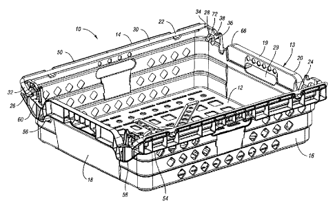
FIGURE 1 illustrates a perspective view of a container according to the
present
invention, having a bail member in the nested position;
-5-
CA 02485544 2004-11-09
WO 03/104094 PCT/US03/15256
FIGURE 2 illustrates a perspective view of a container according to the
present
invention, having the bail member oriented in a first high stack position;
FIGURE 3 illustrates a perspective view of a container according to the
present
invention, having the bail member oriented in a second low stack position;
FIGURE 4a illustrates an end view of the container with the bail member
oriented in the nested position, the rear view being a mirror image thereof;
FIGURE 4b illustrates an end view of the container with the bail member
oriented in the second low stack position, the rear view being a mirror image
thereof;
FIGURE Sa illustrates a side view of the container, having the bail member in
the nested position;
FIGURE Sb illustrates a side view of the container, having the bail member
in the second low stack position;
FIGURE 6 illustrates a partial end view of the container, having the bail
member in the first high stack position;
FIGURE 7 illustrates a partial side view of the container, having the bail
member in the second low stack position;
FIGURE 8a illustrates a top view of the container with the bail member in the
nested position;
FIGURE 8b illustrates a top view of the container with the bail member in the
second low stack position;
FIGURE 9a illustrates a bottom view of the container;
-6-
CA 02485544 2004-11-09
WO 03/104094 PCT/US03/15256
FIGURE 9b illustrates an alternate bottom view of the container;
FIGURE 1 Oa illustrates a partial perspective view of a pair of containers
nested
together;
FIGURE l Ob illusixates a partial perspective view of the container stacked on
top of a like container in the first high stack position;
FIGURE l Oc illustrates a partial perspective view of the container stacked on
top of a like container in the second low stack position; and
FIGURE 11 illustrates a perspective view of the container with the bail
member in the second low stack position.
DETAILED DESCRIPTION OF THE PREFERRED EMBODIMENTS)
A container 10 according to the present invention is illustrated in Figures 1-
11. Container 10 is preferably portable and includes a floor member 12 and an
upstanding wall structure 13 extending upwardly from floor member 12.
Upstanding
wall structure 13 includes a first pair of upstanding opposed side walls 14,
16 and a
second pair of upstanding opposed side walls 18, 20 (also referred to as end
walls.)
Floor member 12 and walls 14-20 are integrally molded to form a unitary
construction
having a compartment area 21 within which goods are stored and transported.
Container 10 preferably is formed from injection molded thermoplastic such as
polyethylene. Container 10 also includes a pair of opposed support members
22,24
(also known in the art as bail arms or bail members), each of which is
selectively
moveable and pivotable among a plurality of positions, with at least three
such
positions illustrated herein.
For ease of discussion, reference will be made to bail arm 22, it being
understood that opposed bail arm 24 is operable in a similar manner. Bail arm
22
includes a first outer end 26 and a second outer end 28, each outer end 26,28
engaged
CA 02485544 2004-11-09
WO 03/104094 PCT/US03/15256
with and being mountably connected to a respective end wall 18,20. Bail arm 22
includes an elongated central bail portion 30 extending across the compartment
area
21 between side walls 14,16. Bail arm 22 also includes intermediate bail
portions
32,34 extending between the central portion 30 and the end portions 26,28.
Bail arms
22,24 are positionable at a nest position such that a like container may nest
fully
therein, useful for when container 10 is empty to achieve space efficiency in
storage
and transport, as shown in Figures 1 and 10a. As shown in Figures 2-3 and l0a-
I Ob,
when in the stack positions, bail arms 22,24 are operable to support a like
container
10' among a plurality of stack positions to achieve mufti-height stacking
capability and
defining various stack heights between the like containers. More particularly,
the like
container 10' is supported upon bail central portion 30 which extends across
the length
of container 10 and is oriented generally parallel to side walls 14,16.
As illustrated in Figures 1-4b and 6-7, each end wall 18,20 includes a
mounting portion 36 for receiving and for mounting bail arms 22,24 thereon.
Specifically, mounting portion 36 includes an opening 38 for receiving outer
bail ends
26,28 therein. Particularly, bail ends 26,28 are bended inward and received
within
opening 38. The opening 38 provides or defines a path, which in the embodiment
illustrated is generally radial, and through which the bail arm 22 may
rotatably and
transversely move. However, it is understood that opening 38 need not have a
radial
curvature to achieve the teachings according to the present invention. As
illustrated
in Figures 4a-4b and 6-7, opening 38 defines a plurality of pivot axes 40,42
about
which bail arm 22 pivots, each pivot axis 40,42 being oriented adj acent to
each other
and oriented at a substantially similar height above the floor member 12, so
that bail
arm 22 achieves one or more of the corresponding nest and stack heights.
More particularly, each opening 38 defines a generally inverted U-shaped or
J-shaped channel, wherein the each pivot axis 40,42 is located at a
corresponding end
of the channel, such that each end of the channel (like pivot axis 40,42) is
of
approximately similar height above floor member 12. Mounting portions 36 also
include a interference portion, comprising a rigid projection 44 extending
into the
opening 38, projection 44 for impeding lateral movement ofbail arm 22 such
that bail
_g-
CA 02485544 2004-11-09
WO 03/104094 PCT/US03/15256
arm 22 can not slide or move laterally from one pivot axis to the other. Proj
ection 44
is preferably rigid and inflexible.
As noted, bail arm 22 is movable and pivotable among a plurality of positions,
including a nest position (Figures 1 and l0a) and a plurality of stack
positions (Figures
2-3 and l Ob-1 Oc), such as a first stack (or high stack) position of Figures
2, 6 and l Ob,
and a second stack (or low stack) position of Figures 3, 7, and l Oc. Thus,
when bail
arm 22 is oriented in the nest position and one of the stack positions, such
as the high
stack position shown in Figure 2, the bail arm 22 is pivotable about a first
one of the
pivot axes, such as axis 40, and movable between the nest position and the
high stack
position. Further, when the bail arm 22 is oriented in an other of the stack
positions,
such as the low stack position shown in Figure 3, the bail arm 22 is pivotable
about
an other of the pivot axes, such as pivot axis 42.
Figures 1, Sa, and 8a illustrate bail arm 22 in the outwardly rotated or
nestable
position. In this orientation, bail arm 22 is supported upon an outer, upper
surface 46
of side wall 14 such that access to the compartment area 21 is unrestricted
and thus
may receive a like container therein in a nest position. In this position,
bail outer ends
26, 28 are disposed in the outer portion 48 of opening 38 and pivotable about
pivot
axis 40. The bail arm 22 is prevented from moving laterally into pivot axis 42
by the
extension of projection 44 into opening 38. Upper surface 46 and its
corresponding
upper side edge 50 include notches 52 that provide access to bail member 22
and that
allow for manipulation of bail member 22 from outside container 10.
As shown in Figures 6-7, wall structure 13 of container 10 also includes a
flanged upper rim 54 of container 10, the flanged upper rim 54 having a
predetemvned
height. Below mounting area 36, flanged rim 54 includes a reinforcement
portion 56
extending below the mounting area 36 and a recessed area 58 for providing
strength
to the bail members 22,24 in their stack positions. End walls 18,20 include at
their
outer ends recessed area SO formed in the upper edge of container 10, within
which
the bail arm 22 rests and is supported when in its second (low) stack
position, as in
Figures 3 and 7. In this second stack position, the intermediate portions
32,34 ofbail
arm 22 rests upon reinforcement area upper surface 60, which is offset
outwardly from
-9-
CA 02485544 2004-11-09
WO 03/104094 PCT/US03/15256
the inboard wall portion 68 and mounting portion 36. The flanged area along
the end
wails 18, 20 define a handle bar 19 by which the container 10 is portable and
thus may
be manipulated. An opening 29 is disposed below handle bar 19 for providing
hand
clearance.
The upper surface 60 of the reinforcement portion 56 defines the lower edge
ofthe recessed area 58. Surface 60 is inclined and angled to support the
intermediate
bail portions 32,34 when in the second (low) stack position (Figure 3).
Reinforcement
portion 56 extends below the mounting portion 36, and particularly below the
pivot
axes 40,42 for providing support and strength to bail member 22 when in its
stack
positions (Figures 2-3). Reinforcement portion 56 is shown having a ribbed
structure
62 and an outer contoured surface b4 generally matching that of the surface 66
which
defines recessed area 58. When in the nested position with a like container
10' as in
Figure 10a, reinforcement portion 56 of an upper container 10' nests
comfortably in
a correspondingly shaped recessed area S8 of a lower container 10.
Proximate mounting portions 36, end walls 18,20 of container 10 include at
their outer ends an inboard side wall portion 68, which is offset inwardly
from the
outer surface of the flange 54, and is oriented generally parallel thereto.
When the bail
member 22 is oriented in the first (high) stack position of Figures 2 and 6,
the bail arm
22 rests and is supported in an upper recess 70 formed in inboard side wall
portion 68.
The inner surface 72 of side wall portion 68 partially defines the interior
surface of the
container. It is noted that opening 38 is not located directly below recess
58, but
instead is offset therefrom. Thus, when the bail arm 22 is supported in recess
58 and
other containers are stacked thereon as in Figure l Oc, the load is supported
directly
thereunder by wall material providing strength thereto, and not by a portion
lacking
some wall material (i.e. opening 38.)
Accordingly, to move the bail member 22 from the first pivot axis 40 to the
second pivot axis 42, the bail member 22 is grasped by a user, such that the
bail arm
ends 26,28 may be moved upwards within opening 38 and moved around the rigid
proj ection 44. Thus, bail arm 22 may be manipulated so that it may be
oriented in one
of the various positions. Since pivot axes 40 and 42 are adjacent and
separated by
-10-
CA 02485544 2004-11-09
WO 03/104094 PCT/US03/15256
projection 44, bail arm 22 is not required to travel a great distance to move
between
the pivot axes. In other words, the present invention provides a compact,
highly
efficient bail mounting area of optimal size and position for the container,
wherein the
pivot axes 40,42 are effectively directly adjacent to each other, but the bail
is not
capable of moving directly axially or laterally between the pivot axes due to
the
intervening projection 44. When in the stack positions, the bail member 22 is
received
within a corresponding grooved recess 74 formed in the bottom surface of floor
member 12, for restricting the relative movement of the upper container 10' to
the
lower container 10 when in a stack position.
As best illustrated in Figure 2, floor 12 has an upper surface 76 with a
plurality
of recessed channels 78 formed therein which are radially extending from a
central
recessed area 80. Channels 78 serve to directed liquid away from the contents
of the
container, and the holes provided 82 in floor 12 (some located within the
channels 78)
serve as an exit for the liquid.
While embodiments of the invention have been illustrated and described, it is
not intended that these embodiments illustrate and describe all possible forms
of the
invention. Rather, the words used in the specification are words of
description rather
than limitation, and it is understood that various changes may be made without
departing from the spirit and scope of the invention.
-11-