Language selection

Search

Patent 2485555 Summary

Third-party information liability

Some of the information on this Web page has been provided by external sources. The Government of Canada is not responsible for the accuracy, reliability or currency of the information supplied by external sources. Users wishing to rely upon this information should consult directly with the source of the information. Content provided by external sources is not subject to official languages, privacy and accessibility requirements.

Claims and Abstract availability

Any discrepancies in the text and image of the Claims and Abstract are due to differing posting times. Text of the Claims and Abstract are posted:

  • At the time the application is open to public inspection;
  • At the time of issue of the patent (grant).
(12) Patent Application: (11) CA 2485555
(54) English Title: ROUND FURNITURE SLIDE
(54) French Title: GLISSIERE ARRONDIE POUR MEUBLE
Status: Dead
Bibliographic Data
(51) International Patent Classification (IPC):
  • A47B 97/00 (2006.01)
  • B66F 19/00 (2006.01)
  • F16M 13/00 (2006.01)
(72) Inventors :
  • EDWARDS, DONALD V. (United States of America)
(73) Owners :
  • SIMTEC, CO. (United States of America)
(71) Applicants :
  • SIMTEC, CO. (United States of America)
(74) Agent: MACRAE & CO.
(74) Associate agent:
(45) Issued:
(22) Filed Date: 2004-10-21
(41) Open to Public Inspection: 2005-04-21
Examination requested: 2004-10-21
Availability of licence: N/A
(25) Language of filing: English

Patent Cooperation Treaty (PCT): No

(30) Application Priority Data:
Application No. Country/Territory Date
60/513,065 United States of America 2003-10-21
10/967,971 United States of America 2004-10-19

Abstracts

English Abstract


An apparatus for use in at least one of movement of at least one
of furniture, appliances and movable wall structures and as a
protective pad for floors wherein said apparatus is placed between
such furniture to be moved and such floors. The apparatus comprises
a first member formed from a first predetermined solid material
having each of a first predetermined configuration and a first
predetermined thickness. An outer perimeter of the first member
having a first predetermined length. Such first predetermined
configuration has a plurality of surfaces. A second member is formed
from a second predetermined material having a second predetermined
configuration and a second predetermined thickness and having a first
surface engageable with the upper surface of the first member. An
outer perimeter of the second member has a second predetermined
length which is shorter than the first predetermined length thereby
forming an exposed portion on the upper surface of the first member
disposed between the outer perimeter of the first member and the
outer perimeter of the second member. The second member being formed
from a compressible material having such radially opposed second
surface for contacting a predetermined portion of such at least one
of such furniture, appliance and movable wall structures to be moved.


Claims

Note: Claims are shown in the official language in which they were submitted.


I claim:

1. An apparatus for use in at least one of movement of at
least one of furniture, appliances and movable wall structures
and as a protective pad for floors wherein said apparatus is
placed between such furniture, appliances and movable wall
structures to be moved and such floors, said apparatus
comprising;
(a) a first member formed from a first predetermined
solid material having each of a first predetermined
configuration and a first predetermined thickness, an outer
perimeter of said first member having a first predetermined
length, said first predetermined configuration having a
plurality of surfaces including an upper surface and a bottom
surface;
(b) a second member formed from a second predetermined
material having a second predetermined configuration and a
second predetermined thickness and having a first surface
engageable with a predetermined portion of said upper surface
of said first member, an outer perimeter of said second member
having a second predetermined length which is shorter than said
first predetermined length thereby forming an exposed portion
on said upper surface of said first member disposed between
said outer perimeter of said first member and said outer

13


perimeter of said second member, said second member being
formed from a compressible material having a substantially
radially opposed second surface for contacting a predetermined
portion of such at least one of such furniture, appliance and
movable wall structures to be moved.

2. The apparatus, according to claim 1, wherein said
first predetermined configuration is generally circular.

3. The apparatus, according to claim 1, wherein said
plurality of surfaces of said first member includes an
intermediate recessed surface, having a third predetermined
configuration, that is substantially radially opposed to said
bottom surface and is substantially centrally disposed for
retaining said second member.

4. The apparatus, according to claim 3, wherein said
exposed portion on said upper surface of said first member
disposed between said outer perimeter of said first member and
said outer perimeter of said second member serves as a support
portion.

14


5. The apparatus, according to claim 3, wherein said
third predetermined configuration is generally round.

6. The apparatus, according to claim 1, wherein said
second member is secured to said first member by means of an
adhesive.

7. The apparatus, according to claim 1, wherein said
second predetermined material of said second member is an
elastomeric material.

8. The apparatus, according to claim 7, wherein said
elastomeric material is selected from a group including natural
rubber, synthetic rubber, polyurethane, ethylene vinyl acetate
and various combinations thereof.

9. The apparatus, according to claim 8, wherein said
elastomeric material is ethylene vinyl acetate.

10. The apparatus, according to claim 1, wherein said
bottom surface of said first member has a predetermined
contour.


15


11. The apparatus, according to claim 10, wherein said
predetermined contour includes a generally flat bottom portion
and an arcuate portion disposed between a side wall portion
having a fourth predetermined configuration and said generally
flat bottom portion.

12. The apparatus, according to claim 11, wherein said
fourth predetermined configuration includes a taper from an
upper edge of said side wall portion to a bottom section of
said side wall portion that merges with said arcuate portion of
said bottom surface.

13. The apparatus, according to claim 1, wherein said
second surface of said second member further includes a double
faced adhesive pad for attaching said apparatus to an item of
furniture.

14. The apparatus, according to claim 1, wherein said
first predetermined material of said first member is selected
from a group of plastic materials including polyethylene,
polypropylene, nylon, tetrafluoroethylene, polyoxymethylenes
and various mixtures thereof.


16


15. The apparatus, according to claim 14, wherein said
plastic material is high density polyethylene.

16. The apparatus, according to claim 1, wherein said
bottom surface of said first member includes a recessed surface
that is radially opposed to said first surface of said second
member.

17. The apparatus, according to claim 16, wherein said
recessed bottom surface further includes a third member
disposed within said recessed bottom surface of said first
member, said third member formed from a third material and
having a fourth predetermined configuration and a third
predetermined thickness.

18. The apparatus, according to claim 17, wherein said
third member is secured to said first member by means of at
least one of an adhesive, a mechanical snap, friction fit and
various combinations thereof.

19. The apparatus, according to claim 17, wherein said
third material is selected from a group including felt,
tetrafluoroethylene and polyethylene.


17


20. The apparatus, according to claim 19, wherein said
third material is felt.

21. The apparatus, according to claim 18, wherein said
third member is secured to said first member by means of said
mechanical snap.


18
Description

Note: Descriptions are shown in the official language in which they were submitted.


CA 02485555 2004-10-21
ROUND FURNITURE SLIDE
CROSS REFERENCE TO RELATED APPLICATIONS
This application is closely related to and claims benefit
from U. S. Provisional Application Serial No. 60/513,065 filed
October 21, 2003.
FIELD OF THE INVENTION
The present invention relates, in general, to an aid for
moving furniture and, more, particularly, the present invention
relates to a furniture slide which also serves as a caster
under furniture.
BACKGROUND OF THE INVENTION
In both the moving industry and the carpet cleaning
industry it is quite common to be faced with the situation in
which a relatively large piece of furniture or an appliance has
to be moved. With limited manpower it is difficult to pick up
the item and carry it to another location.
There have been a variety of prior art devices that have
been used to assist in the moving of such furniture or
appliance. Most of these devices involve placing the device
under the legs of furniture or under the furniture itself in
order to slide the furniture across the floor.
One problem that has been encountered with many of the
prior art devices is that the furniture can slide off of the
1

CA 02485555 2004-10-21
device while in the process of sliding the furniture across a
floor.
SUMMARY OF THE INVENTION
The present invention provides an apparatus for use in at
least one of movement of at least one of furniture, appliances
and movable wall structures and as a protective pad for floors
wherein said apparatus is placed between such furniture to be
moved and such floors. The apparatus comprises a first member
formed from a first predetermined solid material and having
each of a first predetermined configuration and a first
predetermined thickness, an outer perimeter of the first member
having a first predetermined length. Such first predetermined
configuration has a plurality of surfaces including an upper
surface and a bottom surface. A second member is formed from a
second predetermined material having a second predetermined
configuration and a second predetermined thickness and having a
first surface engageable with the upper surface of the first
member. An outer perimeter of the second member has a second
predetermined length which is shorter than the first
predetermined length thereby forming an exposed portion on the
upper surface of the first member disposed between the outer
perimeter of the first member and the outer perimeter of the
second member when that portion of such at least one of such
2

CA 02485555 2004-10-21
furniture, appliance and movable wall structures to be moved,
and in contact with a radially opposed second surface of the
second member, is smaller than a surface area of the second
predetermined configuration of the second member. The second
member being formed from a compressible material having such
radially opposed second surface for contacting a predetermined
portion of such at least one of such furniture, appliance and
movable wall structures to be moved.
OBJECTS OF THE INVENTION
It is, therefore, one of the primary objects of the
present invention to provide a furniture slide in which the
furniture remains with the slide during movement of the
furniture and does not slip off the slide.
Another object of the present invention is to provide a
furniture slide in which the slide can operate on carpeted
floors.
Still another object of the present invention is to
provide a furniture slide in which the slide can be used as a
caster under the furniture to protect the carpet when the
furniture is not being moved.
3

CA 02485555 2004-10-21
Yet another object of the present invention is to provide
a furniture slide in which the material that contacts the
furniture to be moved is a compressible material.
Still another object of the present invention is to
provide a furniture slide in which the material that contacts
the furniture includes an adhesive pad for securing such
apparatus to the furniture.
Another object of the invention is to provide a furniture
slide in which the material that contacts the floor is disposed
as an insert in the apparatus.
Yet another object of the invention is to provide a
furniture slide in which different inserts can be used for
carpeted floors and for hard surface floors.
In addition to the numerous objects and advantages of the
present invention which have been described with some degree of
particularity above, it should be both noted and understood
that a number of other important objects and advantages of the
invention will become more readily apparent to those persons
who are skilled in the relevant art of furniture moving from
the following more detailed description of the invention,
particularly, when such detailed description is taken in
conjunction with the appended claims.
4

CA 02485555 2004-10-21
BRIEF DESCRIPTION OF THE DRAWINGS
Figure 1 is a top or plan view of the furniture slide
according to an embodiment of the invention.
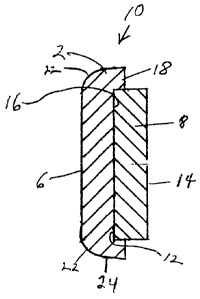
Figure 2 is a cross sectional view of the furniture slide
shown in Figure 1 taken across the lines of II-II.
Figure 3 is a top or plan view of the furniture slide
according to another embodiment of the invention.
Figure 4 is a cross sectional view of the furniture slide
shown in Figure 3 taken across the lines of IV-IV.
Figure 5 is a top or plan view of the furniture slide
shown in Figure 3 showing an alternate embodiment of the
invention.
Figure 6 is a cross sectional view of the furniture slide
shown in Figure 5 taken across the lines of VI-VI.
Figure 7 is a top or plan view of the furniture slide
shown in Figure 3 showing an alternate embodiment of the
invention.
Figure 8 is a cross sectional view of the furniture slide
shown in Figure 7 taken across the lines of VIII-VIII.
Figure 9 is a cross sectional view of the furniture slide
shown in Figures 7 and 8 according to an alternate embodiment
of the invention.

CA 02485555 2004-10-21
BRIEF DESCRIPTION OF THE PRESENTLY
PREFERRED AND VARIOUS ALTERNATE
EMBODIMENTS OF THE PRESENT INVENTION
Prior to proceeding to the more detailed description of
the present invention, it should be noted that for the sake of
clarity in understanding the invention, identical components
with identical functions have been designated with identical
reference numerals throughout the drawing Figures.
Illustrated in the drawing Figures is an apparatus,
generally designated 10, for use in the movement of furniture
on carpeted floors or hard surface floors. Apparatus 10 is
also used as a caster placed under furniture to protect
carpeting or other types of floors. Such items of furniture
would include virtually all items of furniture including
appliances, entertainment centers, bookcases, sofas, desks,
dressers, file cabinets and movable wall structures. Many
furniture or appliance items include leveling screws which can
mar a floor unless the floor is protected. Also many other
pieces of furniture have rather narrow or pointed legs which
can cause problems with the carpeting or other flooring
underneath. The present invention not only is useful in moving
the furniture but can be left under the furniture as a caster
to protect the flooring and still be there in case the
furniture or appliance has to be moved.
6

CA 02485555 2004-10-21
The apparatus 10 is placed between such furniture (not
shown) to be moved and a floor. Apparatus 10 in one embodiment
is used for carpeted floors while in an alternate embodiment
such apparatus 10 is used on hard surface floors. To use
apparatus 10 the item of furniture to be moved would be tilted
slightly and an apparatus 10 would be placed under a corner of
the furniture. This is repeated for each corner. The item to
be moved could then be pushed or pulled to the desired
location. It would, thus, require four apparatus 10 units for
each item of furniture to be moved, although the same units
could be used over and over again.
The apparatus 10 comprises a first member 2 which is
formed a first predetermined material and has each of a first
predetermined configuration and a first predetermined
thickness. The first predetermined configuration having a
plurality of surfaces including a bottom surface 6. The bottom
surface 6 has a predetermined texture for contacting such
carpeted floors and a different texture for use with hard
surface floors. It is presently preferred that such first
predetermined configuration is generally circular.
There is a second member formed from a second
predetermined material. Such second member has a second
predetermined configuration and a second predetermined
7

CA 02485555 2004-10-21
thickness and has a first surface 12 engageable with a surface
radially opposed to the bottom surface 6 of the first member 2.
The second member 8 is formed from such second material which
is a compressible material and has a second surface 14 radially
opposed to the first surface 6 for contact with a predetermined
portion of such furniture to be moved. In one embodiment of
the invention such second member is affixed to the first by the
use of an adhesive.
In one embodiment of the invention the plurality of
surfaces of the first member 2 includes an intermediate
recessed surface 16, having a third predetermined
configuration, that is radially opposed to the bottom surface 6
and is substantially centrally disposed for retaining the
second member 8. Such intermediate recessed surface 16 is
surrounded by a lip 18. Such second member 8 is disposed
within such intermediate recessed surface 16 and the first
surface 12 of the second member 8 is engageable with the first
member 2. It is presently preferred that such third
predetermined configuration of such intermediate recessed
surface 16 is round.
Such second member 8 is formed from a material that is an
elastomeric material and is selected from a group that includes
natural rubber, synthetic rubber, polyurethane, ethylene vinyl
8

CA 02485555 2004-10-21
acetate and various combinations thereof. It is presently
preferred that such second member 8 is ethylene vinyl acetate.
The second member 8 being compressible conforms to any item
that is placed on it. Thus, the second member 8 grips the item
being moved and stays with that item so as to substantially
prevent the item from slipping off of the apparatus 10.
Such first member 2 is formed from such second material.
Such second material is selected from a group of plastic
materials including polyethylene, polypropylene, nylon,
tetrafluoroethylene, polyoxymethylenes and various mixtures
thereof. It is presently preferred that such first member 2 is
high density polyethylene.
The bottom surface 6 of such first member 2 has a third
predetermined contour. It is presently preferred that such
third predetermined contour include outer edges 22 of such
bottom surface 6 of such first member 2 that are slightly
arcuate to assist in sliding over any unforeseen impediment.
This arcuate shape is readily seen in Figures 2, 4 and 6. The
bottom surface 6 is substantially flat with the exception of
the outer edges 22 which are arcuate. It is also presently
preferred that the first predetermined contour of such first
member 2 further includes side walls 24, having a fourth
predetermined contour, that are substantially flat but have a
9

CA 02485555 2004-10-21
slight taper from the top of the side walls 24 to the bottom
where the side walls 24 meet the arcuate outer edges 22 of the
bottom surface 6.
An alternate embodiment of the invention is shown in
Figures 5 and 6 in which a double sided adhesive pad 26 is
adhered to the top of second material 8. The other side of
such adhesive pad 26 is adhered to a corner or a leg of such
furniture when the
apparatus 10 is being used as a caster and kept in place so as
to protect the carpet.
Yet another embodiment of the invention is shown in
Figures 7, 8 and 9. Illustrated therein is an apparatus 10
that can be used for either hard surface floors (Figure 8) or
carpeted floors (Figure 9). In this embodiment the bottom
surface 26 of such first member 2 is recessed. There is a
third member 28 disposed in such recessed pocket that is formed
between the arcuate edges 22 of the first member 2. Such third
member 28 is affixed to the first member by means of an
adhesive. The third member is formed of a third predetermined
material and has a fourth predetermined configuration and a
third predetermined thickness. The third predetermined
material is selected from a group including felt,
tetrafluoroethylene and polyethylene. It is presently

CA 02485555 2004-10-21
preferred that such third predetermined material when used for
hard surface floors is felt. It is also presently preferred
that such third predetermined material when used for carpeted
floors is either polyethylene or tetrafluoroethylene.
As is clearly evident from Figures 8 and 9 the third
member 28 is allowed to protrude beyond the first member when
such apparatus 10 is used for hard surface floors; whereas the
third member is level with the bottom of such first member when
such apparatus 10 is used for carpeted floors. This is
necessary so that there are not any uneven edges that could
catch on the carpet fibers or nap when the apparatus 10 is used
on carpeted floors.
In this embodiment with the third member 28 as an insert
the first member could be made of other and cheaper plastic
materials rather than the ones listed previously. The main
criteria is that the plastic material have sufficient strength
to withstand the forces when a relatively large or heavy object
is being moved, since it is not necessary that it have a low
coefficient of friction since it basically has little contact
with the floor.
While a presently preferred embodiment and alternate
embodiments of the present invention have been described in
detail above, it should be understood that various other
11

CA 02485555 2004-10-21
adaptations and/or modifications of the invention can be made
by those persons who are particularly skilled in the art
without departing from either the spirit of the invention or
the scope of the appended claims.
12

Representative Drawing
A single figure which represents the drawing illustrating the invention.
Administrative Status

For a clearer understanding of the status of the application/patent presented on this page, the site Disclaimer , as well as the definitions for Patent , Administrative Status , Maintenance Fee  and Payment History  should be consulted.

Administrative Status

Title Date
Forecasted Issue Date Unavailable
(22) Filed 2004-10-21
Examination Requested 2004-10-21
(41) Open to Public Inspection 2005-04-21
Dead Application 2008-05-16

Abandonment History

Abandonment Date Reason Reinstatement Date
2007-05-16 R30(2) - Failure to Respond
2007-10-22 FAILURE TO PAY APPLICATION MAINTENANCE FEE

Payment History

Fee Type Anniversary Year Due Date Amount Paid Paid Date
Request for Examination $400.00 2004-10-21
Registration of a document - section 124 $100.00 2004-10-21
Application Fee $200.00 2004-10-21
Maintenance Fee - Application - New Act 2 2006-10-23 $50.00 2006-10-17
Owners on Record

Note: Records showing the ownership history in alphabetical order.

Current Owners on Record
SIMTEC, CO.
Past Owners on Record
EDWARDS, DONALD V.
Past Owners that do not appear in the "Owners on Record" listing will appear in other documentation within the application.
Documents

To view selected files, please enter reCAPTCHA code :


To view images, click a link in the Document Description column. To download the documents, select one or more checkboxes in the first column and then click the "Download Selected in PDF format (Zip Archive)" or the "Download Selected as Single PDF" button.

List of published and non-published patent-specific documents on the CPD .

If you have any difficulty accessing content, you can call the Client Service Centre at 1-866-997-1936 or send them an e-mail at CIPO Client Service Centre.


Document
Description 
Date
(yyyy-mm-dd) 
Number of pages   Size of Image (KB) 
Abstract 2004-10-21 1 33
Description 2004-10-21 12 356
Claims 2004-10-21 6 138
Drawings 2004-10-21 3 44
Representative Drawing 2005-03-24 1 5
Cover Page 2005-04-05 1 44
Correspondence 2004-12-16 1 14
Assignment 2004-10-21 4 129
Correspondence 2005-01-28 1 31
Correspondence 2005-05-24 1 11
Prosecution-Amendment 2006-11-16 3 122