Note: Descriptions are shown in the official language in which they were submitted.
CA 02485696 2004-10-20
METHOD OF AND APPARATUS
F(7R ,.~'Tt~s TN ~~C»'~' WATER
The invention was developed ~ar use in stormwater drainage
systems, and coz'~biried sewer systems (some older US cities have
combined sanitary and stormwater sewers). These sewers are designed
and constructed to~convey water from a developed area into natural.
reCeivir~g water or Other de9tin2~tion. Plhen storm sewers were First
constructed, the qom3 was to remove the water from the developed
area and Convey it into the reCei.ving water 88 quickly as possible.
At that time, no attention was paid to the potent~.al for pollution
from stormwater runoff.
During the last twenty years, stormwater runoff has been
identified as a significant source of pollutivz~ in waters of the
United States. The stormwater runoff from a developed area (a
parking lot, for example) caxi contain ails and other fluids from
leaki.nc~ cars, zinc and heavy metals from brake pads and other
sources, nutrients from fe~'tilizers and air pollution, sedixner~ts,
and garbage and other debris All of these constituents impact the
receiving water that the stormwater drainage system discharges to.
In addition to these pollutants, many older U5 c~.ties have
combined ser~aer systems, in which the sanitary sewer drainage and
stormwater runoff are conveyed .in the same pipes. These systems
i~unction perfectly well when the weather is dry, but have the
potential to overflow during large storms. Hecause wastewater
1
CA 02485696 2004-10-20
treatment plants are designed to handle limited flows, even
frequently recurring st4rms have the potential to exceed the
treatment capacity of the p3ant_ These cases are teamed
combined-sewer overflows (C50s).
With the reauthorization of the Clean Water ACt, Congress
gave ~P~ the authority to regulate discharges to watexs of the
United States from larger stormwater drainage systems, including
CSOs. Over the last four years, the scope of the regulation has
been increased to include many medium sized and small stormwater
drainage systems as well. In response to increasing regulation and
federal oversight, a demand exists for devices which are capable of
removing stormwater-specific pollutants from a flow stream.
Other technologies, including HaySaver's patented physical
separator (U.9. Patents 5,~~6,911 and 6,264,835), rely on gxavity
settling and sedimentation to remove suspended sediments, o~is, and
other floatable debris from stormwater runoff. These systems, while
effective at low flow rates, often include a bypass structure that
allows high flows to pass through ar around the system untreated.
Although the ruaaff during intense storms usually has lower
concentration of pollutants like sediments, nutrients, and oils,
there is often a significant amount of trash, debris, and other
floatable material entrained in the water. The present invention i9
intended to remove these constituents from stvz-mwater or CSO runoff
and retain them in a structure sv that they can be easily removed
during routine maintenance.
The prior art used for this purpose includes several
US-patented systems. These systems often rely on vortex technology
2
CA 02485696 2004-10-20
and hydraulic flow controls to enhance the removal of contaminants
from the influent water, and many of the existing systems include
multiple outlet streams: a single outlet for treated effluent, and a
second outlet for contaminated flow.
The present invention consists of a single con.tainez~, which
contains a chamber to remove and retain large floatable pollutants,
as weld, as a system of one or more permeable barriezs to remove and
retain the sma~.ler pollutants that escape from the first chamber. A
bypass flow path is also provided in case the expected influent flow
rate exceeds the flooo captivity of the invent3.on. In addition to
this preferred form, an alternate form of the invention relies on
external controls to prevent excessive flows from entering the unit,
negating the necessity of a bypass flow path within the unit.
The invention relies on two methods to remove undesirable
contaminants from the .influent stream: physical separation of the
contaminants due to differences in specific gravity, and
interception of contaminants by permeable barriers placed within the
unit.
A vortex cheer is used to swirl runoff water to separate
the contaminants from the grater. Such a vortex chamber has a
conventivz~al input for.~eeding the runoff water under sufficient
head to produce the swirl.
A settlir~g taxsk is at a lower level than tha vortex chamber
and receives the water and the heavier-than-water contaminants.
The vortex chamber is r~ew in that it has a skirt portion
extending downwrardly from the inlet pipe. This skirt portion wi.l1
3
CA 02485696 2004-10-20
have water in it continuously and will, therefore, receive and hold
the lighter-than-water contaminants until they are removed by a
regular cleaniwg.
The skirt portion has a funnel in it which Causes the water
from the swirl to speed up and then expand when it leaves the funnel
anal passes into the settling chamber. The aforesaid increase in
speed followed by an expansion furthez~ tends to separate the
contaminants from the watez~.
A shelf in the Settling chamber acts as means for preventing
the swirling water from resuspending any accumulated material in the
settling chamber..
The head of water in the skirt forces the water ire the
settling chamber to rise along the outer si.dewall of the skirt.
There it passes through permeable barz~iers (which mar be screens) to
a clean water outlet.
The permeable barriers which clean the water have a series of
louvers pro~eCting from the permeable barriers at acute angles to
the direction of flow (See Fig. 9). This e~lables the louvers to
pre~rent contaminants from blocking the permeable barrier.
RIE~ Dfi CR P ION ~"1F T F DRAI9IN
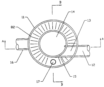
F=G. 1 is a plan view of the preferz~ed form of the invention.
FIC3. 2 i9 8 cross sectional view of the preferred form of the
inve~nti.on taken along line A-A e,s shown, in Fig. 1.
FIG. 3 is a cross sectioz~al view Of the preferred form of the
a.nventioz~ taken along line H~H as shown in Fig. 1.
FIG. 4 is a plan view of a first modified form of the
invent iOn .
4
CA 02485696 2004-10-20
FrG. 5 is a cross sectional view of a first modified form of
the inver~tion taken along line C-C as indicated in Fig. 4.
FIG. 6 i3 a plan view of a second modified farm of the
invention_
FIG. 7 is a cross sectional v:Lew of the second modified ~oxm
of the invention taken. along line p~D as sndicated in Fig. 6.
FIG. B is a plan view of the permeable barriers) 15 that are
included in each form of the invention.
FIG. 9 is a cross sectional view of the permeable barriers)
taken across lire E-E as indicated in FICA. 8.
r'l3TeIL~~D$SCRIPTION QF THF INVEN~~~ON
FIGS. 1, 2, and 3 show the preferred form of the invention.
FIG. 1 is a plan view of the invention. FIG. 2 is a cross sectional
v.~ew taken along line A-A as indicated in FIG. 1 and FIG. 3 is a
cross sectional view takers along l.i_z~e 13-8 as indicated in FIG. 1 .
The iz~.vez~tioa is housed in a container, comprising a floor
z5, a top 21 with an opening 22 fvr access, and side walls 11. A
fluid carrying contaminants to be separated is introduced to the
system through inlet 12, which penetrates side wall 11 and conveys
the fluid to pipe 13, Tnlet means 12 conveys a fluid that has
suff~,cient upstream head to force the fluid through the system, as
indicated by the vertical section of inlet means 12 in FIG. 2_ From
pipe 13, the fluid enters vortex chamber 14, tangentially, as
commonly done, where the swirling action helps to separate the
contaminants from the fluid, Floating contaminants are stored in
the vortex chamber 74, trapped by the roof 21 of the vortex chamber.
In the roof 21 of the vortex Chamber i~ a sealed opening Z2 that can
CA 02485696 2004-10-20
be removed to provide access to the accumulated contaminants within
the chamber .
The cylindrical sidewall, of vortex chamber 14, extends
considerabhy below the lowest part of inlet pipe '12, to form a skirt
portion which in turn forms a storage chamber for lighter-than-water
contaminants. G~hen oil or other low density contaminants are
separated from the water by the swirling action, such low-density
contaminants remain on the surface of the water that has moved
dowxiward from the spac~ where the swirl occurred. These
light-weight contaminants remain on the surface of the water in tank
11, until the system is given its pexiodic cleaning at which time
such Contaminants are removed from the lower part of the vortex
chamber '14 through opening Z2 in the top of that Chamber.
The fluid exits vortex chamber 14 by flowing downward through
the incline8 walls 27. The inclined walls 27 maintain the swirling
flew path while iriCreasing the velocity of the fluid through this
part of the invention, When the Fluid passes through the narrowest
part of inclined walls 27 and enters settling chamber Z6, the f.Luid
loses g significant amount of energy because of the sudden
expansion. This energy loss helps to settle wontazninants that are
denser than the fluid to the floor Z5 of the structure. Once the
material ~.s settled on floor 25 of the structure, a shelf Z9
prevents the swirling currents from, resu9pending the accumulated
material, and the material is retained in the structure until it is
removed.
Once the Fluid flows from the confines of chamber ~4 down
through ~.nclizied walls 27 and into settling chamber 26, it is driven
6
CA 02485696 2004-10-20
outward around skirt 28 and up through pe~e~le barrier or barriers
15. Each of the one or mere permeable barrxer(s) 15 is a plate or
similar structure containing a plurality of openings intended to
allow the fluid to pass through the permeable barrier (screen) while
trapping contaminants within the confines of the settling chamber
26. The openings in permeable barxier(15) can be sized to trap
particular contaminants, and can be designed in such a way as to not
impede the flow. This is accomplished through the use o~ louvers
angled against the direction of flow, as shown in FIGS. S and 9.
Additionally, more than one permeable barrier 15 may allow for
enhanced pollutant removal by the present invention. Permeable
barriers) 15 are placed within the unit in a horizontal fashion,
parallel with the unit floor and allowing fluid to flow vertically
thxough the barrier. ~n instances where multiple barriers are used,
the sire of the openings may or may not vary with the different
barriers. This variability allows the present invention to bE
designed for specific instances in which particular contaminants are
expected and desired to be removed.
Once the fluid flow has passed through permeable bsrrier(s)
15, it enters outlet means 15, which conveys the treated effluent to
its destination. The lowest point of outlet means 16 is at the same
elevation or lower than the lowest point of inlet means 12. Because
of this relationship. the present invention functions under gxavity
flow, and requires no additional sources of energy to operate. This
relationship al8v prevents the present invention from causing a
backup in inlet means 12. Said backup could potentially cause
problems With upstream structures, and is a generally undesirable
7
CA 02485696 2004-10-20
featuxe o~ such systems.
During periods of high influent flow xates, an additional.
flow path through the present invention is possible. In this case,
the influent fluid enters the present invention through inlet means
12, is conveyed into vortex chamber 14 by conveyance means 13, and
enters settling chamber 26 from vortex chamber 14 as it does under
normal flow conditions. If the plurality of openings in permeable
barriers) 15 does not allow the full flow of the fluid to pass
through to the outlet means 16, the fluid will be forced through the
overflow 17_ The fluid enters overflow means 17 from a point below
the bottom of the-lowest permeable barriers) 15, and is forced
upward through overflow means 17 by hydrostatic pressure. When the
influent flow rate to the present invention is great enough, this
hydrostatic pressure will force the fluid upwards through the open
top of overflow 17, allowing the excess water to enter outlet means
16 Without passing through permeable barriex(s) 15. This flow path
is utilized during periods when the flow rate is high enough that
the influent fluid cannot pass through the plurality of openings in
permeable barriers) 15, or if the plurality of openings in
permeable barriers) 15 are blocked by some item that prevents
normal operation.
Openings 24 in the top of the unit itself and 22 in the top
v~ the vortex chamber allow access to the trapped contaminants.
This access can be used for environmental monitoring, process
monitoring, or maintenance purposes. In addition to the floatable
storage within the vortex Chamber, these openings also a3low access
to the settling Chamber to remove any pollutants that have settled
a
CA 02485696 2004-10-20
to the fl.oar of the device.
~~~rn l~~DrFTED ~~RM ~F THE INVENTZQN_
A first modified form of the invention is shown in FzG. 4 and
FTG. 5. During normal flow conditions, this form of the invention
functions identically to the preferred form. 'Ibis modified form o~~
the invention, however, does not ~.acZude the overflow pipe 17 found
in the preferred form. Because this overflow i,s not a part bf the
modified form of the ,ixlvention, it functions differently in pez~iods
of high influent flow rate.
During periods of high influent flow rate, the ~luid backs up
in the inlet mesn~ 112 until the hydrostatic prQSSUre is sufficient
to drive the Fluid through the permeable barri.er(s) 115. Most
often, the modified form of the invention will be used with an
external. flow control that will prevent the high flows from entering
the invention,
~ ~~ND MODTFTEn ~OFtM OF~HE I~FN~ ON
A second modified form of the invention is shown in FIG. 6
and FIG. 7. This modified form includes a diversion structure,
which pz~ovides the hydraulic controls referenced xn the first
modified form pf the invention. FIG. 6 shows a plan view of the
invention with the diversion structure. In this Form, the inlet
~"m~eans 201 conveys Contaminated fluid to the diversion structure 200.
The fluid is held back by Flow control 202, which is a weir with a
crest elevation higher than the invent of Conveyance 204. During
periods of low flow, we~.r 202 fOxces the influent water into the
container 11, which i$ the same as the fixst modified farm of the
invention. The tz~eated fluids e~cits container 11 and returns to
9
CA 02485696 2004-10-20
structure 200 through conveyance means 205, The fluid then exits
the system through outlet 203,
During periods of high influent flow rate, t.tlP fluid level in
chamber 206 rises due to the backup of fluid in tank 11. Wren the
fluid level exceeds the elevation of the crest of weir 202, the
fluid flows over the weir, by passing tank 11, and flows directly to
outlet means 203. This flow path negates the necessity for the
overflow flow path described in the preferred form of the invention.