Language selection

Search

Patent 2485774 Summary

Third-party information liability

Some of the information on this Web page has been provided by external sources. The Government of Canada is not responsible for the accuracy, reliability or currency of the information supplied by external sources. Users wishing to rely upon this information should consult directly with the source of the information. Content provided by external sources is not subject to official languages, privacy and accessibility requirements.

Claims and Abstract availability

Any discrepancies in the text and image of the Claims and Abstract are due to differing posting times. Text of the Claims and Abstract are posted:

  • At the time the application is open to public inspection;
  • At the time of issue of the patent (grant).
(12) Patent: (11) CA 2485774
(54) English Title: SOFT MAGNETIC COMPOSITE POWDER METAL CORES
(54) French Title: NOYAUX METALLIQUES A POUDRE COMPOSITE FAIBLEMENT FERROMAGNETIQUES
Status: Deemed expired
Bibliographic Data
(51) International Patent Classification (IPC):
  • H02K 1/00 (2006.01)
  • H01F 3/08 (2006.01)
  • H02K 1/02 (2006.01)
  • H02K 1/12 (2006.01)
  • H02K 1/18 (2006.01)
  • H02K 15/02 (2006.01)
(72) Inventors :
  • ENGQUIST, JOHN (United States of America)
  • WEGNER, ED (United States of America)
(73) Owners :
  • AMSTED INDUSTRIES INCORPORATED (United States of America)
(71) Applicants :
  • AMSTED INDUSTRIES INCORPORATED (United States of America)
(74) Agent: GOWLING WLG (CANADA) LLP
(74) Associate agent:
(45) Issued: 2008-09-16
(22) Filed Date: 2004-10-22
(41) Open to Public Inspection: 2005-09-08
Examination requested: 2004-10-22
Availability of licence: N/A
(25) Language of filing: English

Patent Cooperation Treaty (PCT): No

(30) Application Priority Data:
Application No. Country/Territory Date
10/794,627 United States of America 2004-03-08

Abstracts

English Abstract

A stator core assembly for use in an electrical machine is provided. The stator core assembly includes a plurality of core components. Each core component forms an arcuate section of the stator core assembly. Each core component is comprised of at least two core component sections, with each core component section adjacent another core component section. Each core component section is formed of a ferrous magnetic powder metal particles which are generally mutually insulated. Such ferrous magnetic powder metal particles are pressure formed into the core component section.


French Abstract

Il est décrit un noyau statorique pour utilisation dans une machine électrique. Le noyau statorique comprend une pluralité de composants de noyau, chacun desdits composants constituant une section arquée du noyau statorique. Chaque composant de noyau comporte au moins deux sections de composant de noyau, où chaque section de composant de noyau est adjacente à une autre section de composant de noyau. Chaque section de composant de noyau est formée de particules de poudre de métal ferromagnétique qui sont, en règle générale, mutuellement isolées. De telles particules de poudre de métal ferromagnétique sont formées sous pression dans la section de composant de noyau.

Claims

Note: Claims are shown in the official language in which they were submitted.


CLAIMS

1. A stator core assembly for use in an electrical machine, the stator core
assembly
comprising a plurality of core components,

each core component having a flux transfer surface, a winding support section
extending
radially from the flux transfer surface, and a base section into which the
winding support section
extends,

each core component forming an arcuate section of the stator core assembly,

each core component comprised of a plurality of core component sections, each
core
component section adjacent another core component section along a
circumferential plane of the
stator core assembly,

each core component section being of ferrous magnetic metal powder particles
generally
mutually insulated and pressure formed into the core component section,

wherein each core component section is insulated from each adjacent core
component
section,

and wherein each core winding support section has a generally rounded and
smooth outer
surface for receiving a core winding therearound.


-6-

Description

Note: Descriptions are shown in the official language in which they were submitted.


CA 02485774 2004-10-22
SOFT MAGNETIC COMPOSITE POWDER METAL CORES
BACKGROUND OF THE INVENTION
The present invention relates to core components for use in electrical
machines and, more
particularly, a stator core assembly for use in an electrical machine, most
typically an electrical
motor.
Electrical machines such as motors and generators have a stationary element,
usually
termed as stator, and movable or rotating elements, typically termed the
rotor. The interaction
between the stator and the rotor is caused by the interaction of a magnetic
field generated by
either the stator or the rotor. Such magnetic field is usually generated or
induced by electric
currents in a winding placed on either the stator or the rotor. Such winding
usually comprises a
plurality of coils wound about a winding support. The winding support is
usually comprised of a
soft magnetic material which traditionally is made of laminations of materials
of selected steel
materials. The laminations are insulated from each other in order to reduce
eddy currents.
It has become known to replace the laminated steel components of stator or
rotor cores
with ferro-magnetic particles that are compacted in a powder metallurgy
operation to form the
winding support. 'hhe ferro-magnetic particles themselves are essentially
electrically insulated
from cacl~ other so that the resulting compacted product exhibits a low eddy
current loss in a
manner similar to the prior art use of a stack of steel laminations. Such use
of compacted metal
powders comprised of ferro-magnetic particles for cores in electrical machines
is disclosed in US
Patent Nos. 6,300,702 and 6,441,530.
It is another object of the present invention to provide an improved corn
component for
use irr electrical tnachitie;s wh~;rcin the c;ouc comprises at lc~a.sr two
core cornpon;Trot section, each
Ii~rrnc;d of a cornpactcd fr~rrc~~.~s rnagrxctic powder.


CA 02485774 2004-10-22
SUMMARY OF THE INVENTION
25 The present invention provides an improved stator assembly for an
electrical machine.
More specifically, the present invention provides an improved stator core for
use in an electrical
motor or generator. The improved stator core comprises a plurality of core
components. Each
core component forms an arcuate section of the stator core assembly, which is
understood to be a
generally cylindrical structure. Each core component itself comprises at least
two core
30 component sections. Each core component section is adjacent another core
component section
along a circumferential plane of the stator core assembly.
Further, each core component section is formed of ferrous magnetic metal
powder
particles. Such particles are further processed to be generally mutually
insulated. The ferrous
magnetic metal powder particles are pressure formed into the core component
section form.
35 It is a feature of the present invention that such an improved core
assembly comprised of
a plurality of core component sections formed of mutually insulated ferrous
magnetic powder
metal particles provides improved performance due to the reduced eddy current
losses in the
electrical machine.
It is a further feature of the present invention shat the stator core assembly
core
40 components include winding supports. These winding supports are comprised
of at least two core
component sections. Duc to the use of the pressure formed ferrous magnetic
powder metal
particles, the winding support has a ~Tenerally rounded and smooth outer
profile. This is a
desirable feature as the wire windings around such winding supports would not
he subject to
contact with sharp edges wliichcould othe~vvise damage the insulation of the
wire windings and
45 lead to reduced performance a.nrcl even failure ef the electrical machine.
._.,


CA 02485774 2004-10-22
BRIEF DESCRIPTION OF THE DRAWINGS
In the drawings,
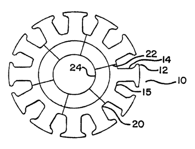
Figure 1 is an axial view of a stator of an electrical machine in accordance
with an
s0 embodiment of the present invention;
Figure 2 is a perspective view of two core component sections combined to form
a core
component in accordance with the present invention;
Figure 3 is a perspective view of two core component sections separated from
each other
for this view;
Figure 4 is a perspective view of four core component sections combined to
form a core
component, and
Figure 5 is a perspective view of four core component sections separated for
this view.
DESCRIPTION OF THE PREFERRED EMBODIMENTS
Referring now to Figure 1 of the drawings, a stator core assembly is shown
generally at
60 10. The stator core assembly is seen to be comprised of a base section 20,
which is generally
circular in shape, having, an inner surface 24. Extending outwardly from base
section 20 are a
plurality of winding supports 14. Each winding support is seen to be a
generally arcuate
structure having rounded surfaces. itator section flux surfaces 12 are seen to
be expanded at the
end of each winding :~ul~purt l4. It is understood that winding supports 14
are of a generally
65 rounded smooth outer profile due to the subsequent winding of wires about
winding support 14
in the assembly of the electrical machine, such as a generator or motor.
R~f~~~rin~ now 1~> lvigures 2 and 3, a detailed perspective view of a stator
section 11 is
shown. Stator assc;mbiy l 0 is seen to be comprised of a pluJVr.lity of core
components I 5.
_3


CA 02485774 2004-10-22
Referring now to Figure 2, stator core component 1 S is seen to be comprised
of stator
70 section 11 and stator section 13. Stator section 11 and stator section 13
are similar in that each is
comprised of a base section 20 having an inner surface 24. Base section 20 is
seen to have an
adjoining surface 22 which is adjacent and abuts a similar adjoining surface
of an adjacent core
component to form the stator core assembly as seen in Figure 1.
Stator core section 13 is seen to be further comprised of winding support 14
extending
75 radially outwardly from base section 20. Stator section flux surface 12 is
seen to be an expanded
portion at the end of winding support 14. It should be understood that winding
support 14, base
section 20, and stator section flux surface 12 are identical whether part of
stator section 11 or
stator section 13.
In Figure 2, stator section 1 l and stator section 13 are seen to be adjacent
along joining
80 plane 26. In Figure 3, adjoining surface 28 of stator section 13 is seen to
be spaced from
adjoining surface 30 of stator section I I . It should be understood that
appropriate insulating
material such as an oxide layer is utilized to electrically insulate adjoining
surface 28 from
adjoining surface 30.
It should also be understood that winding support 14, when adjacent a similar
winding
85 support in both stator secti~x~ 11 and stator section 13 combine to form a
generally rounded and
smooth outer prof le winding suppor-k. This is desirable due to the subsequent
winding of
electrical wires about winding; support 14 su~:lr that the insulation on such
wires will not be
subjected to a sharp surface or corner type edge. 'I"his could lead to reduced
performance of the
stator corca assembly or even failrrrc: of the electrical machine.
90 R.eferrir;g rrraw to I'igtures 4 arr<l 5, the secorul embodiment of the
present invention is
shown. Staiur core: corrrputcr~t SO oor~ipr~iscs stator sections 41, 42, 43,
and 44. All of stator
4 _.


CA 02485774 2004-10-22
sections 41, 42, 43, and 44 are identical except for the outer surface rounded
edges of sections 41
and 44, so the detailed explanation of stator section 41 will be equally
applicable to the other
stator sections. Stator section 41 is seen to comprise a base section 35 that
is an arcuate section
95 ultimately forming a circular structure of the core assembly. Base section
40 includes an inner
surface 35 that is generally circular in nature. Extending radially outwardly
from base section 40
are a plurality of winding supports 34. Winding supports 34 are seen to have
generally an
arcuate or rounded outer surfaces. The stator section flux surface 32 is seen
to be an expanded
outer edge of winding support 34.
100 Stator section 41 is seen to be adjacent to abut stator section 42 along
junction 36.
Similar junctions are present between stator sections 42 and 43, and 43 and
44.
A view of Figure 4 shows stator sections 41, 42, 43, and 44 assembled in an
abutting
relationship, whereas the view of figure 5 shows each of stator sections 41,
42, 43, and 44
separated from each other.
I 05 It should be understood that the abutting surfaces between stator section
41 and 42 are
generally flat but also including an insulating material such that stator
section 41 and 42 are
electrically insulated from each other. Similar comments can be made to the
adjoining sections
of stator sections 42 and 43, and 43 and 44.
While it is understood that winding supports 34 include a flat section
abutting the
I 10 adjacent winding support section of tl~e: adjacf:nt stator section, the
outer surfaces of winding
support :34 are of a generally rounded and surooth outer profrle. 'This is
desirable as electrical
wires are ultimately wound about winding support 34 to form the desirable coil
structure for the
electrical machine that they yore component 50 ultimately fc~rr~is a portion
of the stator core
asserT~bly.

Representative Drawing
A single figure which represents the drawing illustrating the invention.
Administrative Status

For a clearer understanding of the status of the application/patent presented on this page, the site Disclaimer , as well as the definitions for Patent , Administrative Status , Maintenance Fee  and Payment History  should be consulted.

Administrative Status

Title Date
Forecasted Issue Date 2008-09-16
(22) Filed 2004-10-22
Examination Requested 2004-10-22
(41) Open to Public Inspection 2005-09-08
(45) Issued 2008-09-16
Deemed Expired 2021-10-22

Abandonment History

There is no abandonment history.

Payment History

Fee Type Anniversary Year Due Date Amount Paid Paid Date
Request for Examination $800.00 2004-10-22
Registration of a document - section 124 $100.00 2004-10-22
Application Fee $400.00 2004-10-22
Maintenance Fee - Application - New Act 2 2006-10-23 $100.00 2006-08-15
Maintenance Fee - Application - New Act 3 2007-10-22 $100.00 2007-08-09
Final Fee $300.00 2008-06-25
Maintenance Fee - Application - New Act 4 2008-10-22 $100.00 2008-08-14
Maintenance Fee - Patent - New Act 5 2009-10-22 $200.00 2009-10-01
Maintenance Fee - Patent - New Act 6 2010-10-22 $200.00 2010-09-30
Maintenance Fee - Patent - New Act 7 2011-10-24 $200.00 2011-09-30
Maintenance Fee - Patent - New Act 8 2012-10-22 $200.00 2012-10-01
Maintenance Fee - Patent - New Act 9 2013-10-22 $200.00 2013-09-30
Maintenance Fee - Patent - New Act 10 2014-10-22 $250.00 2014-10-20
Maintenance Fee - Patent - New Act 11 2015-10-22 $250.00 2015-10-19
Maintenance Fee - Patent - New Act 12 2016-10-24 $250.00 2016-10-17
Maintenance Fee - Patent - New Act 13 2017-10-23 $250.00 2017-10-16
Maintenance Fee - Patent - New Act 14 2018-10-22 $250.00 2018-09-21
Maintenance Fee - Patent - New Act 15 2019-10-22 $450.00 2019-09-20
Maintenance Fee - Patent - New Act 16 2020-10-22 $450.00 2020-09-18
Owners on Record

Note: Records showing the ownership history in alphabetical order.

Current Owners on Record
AMSTED INDUSTRIES INCORPORATED
Past Owners on Record
ENGQUIST, JOHN
WEGNER, ED
Past Owners that do not appear in the "Owners on Record" listing will appear in other documentation within the application.
Documents

To view selected files, please enter reCAPTCHA code :


To view images, click a link in the Document Description column. To download the documents, select one or more checkboxes in the first column and then click the "Download Selected in PDF format (Zip Archive)" or the "Download Selected as Single PDF" button.

List of published and non-published patent-specific documents on the CPD .

If you have any difficulty accessing content, you can call the Client Service Centre at 1-866-997-1936 or send them an e-mail at CIPO Client Service Centre.


Document
Description 
Date
(yyyy-mm-dd) 
Number of pages   Size of Image (KB) 
Abstract 2004-10-22 1 15
Description 2004-10-22 5 214
Claims 2004-10-22 3 79
Drawings 2004-10-22 2 32
Representative Drawing 2005-08-15 1 8
Cover Page 2005-08-18 1 37
Claims 2007-05-16 2 55
Claims 2007-12-13 1 24
Cover Page 2008-09-03 1 39
Assignment 2004-10-22 8 210
Prosecution-Amendment 2007-01-26 2 71
Prosecution-Amendment 2007-05-16 4 180
Prosecution-Amendment 2007-08-07 3 91
Prosecution-Amendment 2007-12-13 3 125
Correspondence 2008-06-25 2 50
Correspondence 2008-11-19 1 16
Correspondence 2008-12-23 1 13
Correspondence 2008-12-09 2 43
Correspondence 2010-06-10 8 327
Correspondence 2010-06-22 1 15