Note: Descriptions are shown in the official language in which they were submitted.
CA 02486032 2004-11-15
WO 03/098039 PCT/US03/15547
HUB MOTOR FORMED IN A WHEEL AND A METHOD
ASSOCIATED THEREWITH
Background
Transportation devices have contained motors in the past. Certain limitations
of these prior art
motors have been realized. One of these limitations is that engines operate at
a relatively high speed
(e.g. 5,000 to 10,000 revolutions per minute) while wheels on vehicles operate
at much lower speeds
(e.g. a 26-inch bicycle wheel may operate at 100 revolutions per minute).
Summary
In one exemplary embodiment disclosed herein, a wheel for a transportation
device may include:
an engine formed in the wheel; and a carburetor fixedly attached to the
transportation device, the
carburetor being fluid communication with the engine.
In another exemplary embodiment disclosed herein, a wheel defining a first
axis for a
transportation device may include: an engine formed in the wheel, the engine
comprising a crankshaft; a
first gear having a first sun'ace, the first surface being gearingly coupled
to the drive shaft, the first gear
being concentric to the first axis; a second gear integrally formed on the
first gear first surface; and
wherein the second gear is drivably engaged with the transportation device.
In another exemplary embodiment disclosed herein, a method of moving a
transportation device
may include: providing an engine formed in a wheel, the engine comprising a
piston; providing a
carburetor fixedly attached to the transportation device; mixing a combustible
liquid with air in the
carburetor to form a combustible mixture; transferring the combustible mixture
to the engine; exploding
the combustible mixture in the engine to move the piston; and transferring the
piston movement to the
transportation device.
In another exemplary embodiment disclosed herein, a wheel for a transportation
device may
include: a hub comprising an external cylindrical face; and an internal
combustion engine formed on the
external cylindrical face.
In another exemplary embodiment disclosed herein, a wheel for a vehicle may
include: a mixing
means for creating a combustible mixture, the mixing means fixedly attached to
the vehicle; and a
combusting means for igniting the combustible mixture, the combusting means
rotationally attached to the
vehicle.
Brief Description of the Drawing
Illustrative embodiments are shown in Figures of the Drawing in which:
FIG. 1 shows a schematic diagram of an exemplary vehicle (e.g. a bicycle)
provided with a wheel
including a hub motor.
CA 02486032 2004-11-15
WO 03/098039 PCT/US03/15547
FIG. 2 shows perspective view of a hub motor.
FIG. 3 shows a perspective view of an exemplary axle assembly.
FIG. 4 shows a front elevation view the axle assembly of FIG. 3.
FIG. 5 shows a cross-sectional view taken across plan 5-5 of FIG. 4 of the
axle assembly of FIG.
3.
FIG. 6 shows a side elevation view the axle assembly of FIG. 3.
FIG. 7 shows a front elevation view a cover.
FIG. 8 shows a perspective view of a hub.
FIG. 9 shows a front elevation view of the hub of FIG. 8.
FIG. 10 shows a top plan view of the hub of FIG. 8.
FIG. 11 shows a side elevation view of the hub of FIG. 8.
FIG. 12 shows a cross-sectional view take across plane 12-12 of FIG. 10 of the
hub of FIG. 8.
FIG. 13 shows a side elevation view of a piston.
FIG. 14 shows a bottom plan view of the piston of FIG. 13.
FIG. 15 shows a front elevation view of the piston of FIG. 13.
FIG. 16 shows a side elevation view of a crank arm.
FIG. 17 shows a perspective view of an input assembly.
FIG. 18 shows a front elevation view of the input assembly of FIG. 17.
FIG. 19 shows a side elevation view of a first distal end of the input
assembly of FIG. 17.
FIG. 20 shows a side elevation view of a second distal end of the input
assembly of FIG. 17.
FIG. 21 shows a perspective view of a first gear assembly.
FIG. 22 shows a side elevation view of a first face of the first gear assembly
of FIG. 21 with a
detail showing an exemplary pin detent.
FIG. 23 shows a cross-sectional view taken across plane 23-23 of FIG. 22 of
the first gear
assembly of FIG. 21.
FIG. 24 shows a side elevation view of the first gear assembly of FIG. 21.
FIG. 25 shows a perspective view of a second gear assembly.
FIG. 26 shows a side elevation view of the second gear assembly of FIG. 25.
FIG. 27 shows a perspective view of a third gear assembly.
FIG. 28 shows a front elevation view of the third gear assembly of FIG. 27
with a detail showing
an exemplary pin detent.
FIG. 29 shows a cross-sectional view take across plane 29-29 of FIG. 28 of the
third gear
assembly of FIG. 27.
FIG. 30 shows a side elevation view of the third gear assembly of FIG. 27.
FIG. 31 shows a back elevation view of the third gear assembly of FIG. 27.
FIG. 32 shows a perspective view of an overdrive cover.
FIG. 33 shows a perspective view of a pad.
FIG. 34 shows a perspective view of an overdrive disk and a starter disk.
FIG. 35 shows a perspective view of the hub motor of FIG. 2.
FIG. 36 shows a perspective view of the hub motor of FIG. 35 with covers
removed therefrom and
a portion of an engine shown in cross-sectional form.
-2-
CA 02486032 2004-11-15
WO 03/098039 PCT/US03/15547
FIG. 37 shows a perspective view an exemplary embodiment of an assembly
contained within the
hub motor of FIG. 35.
FIG. 38 shows a side view of the assembly of FIG. 37 provided with an
exemplary carburetor.
FIG. 39 shows a perspective view of an exemplary starter assembly and an
exemplary overdrive
assembled with the exemplary axle assembly of FIG. 3.
FIG. 40 shows a cross-sectional side view of a starter/overdrive selector
assembly assembled
contained within the exemplary axle assembly of FIG. 39.
FIG. 41 shows a side elevation view of an exemplary starter/overdrive selector
assembly rod.
FIG. 42 shows a side elevation view of a hub motor provided with fuel rail and
a confined portion.
FIG. 43 shows a cross-sectional view of the hub motor provided with the fuel
rail of FIG. 42.
FIG. 44 shows a cross-sectional view of a rotary valve.
Detailed Description
Provided herein is a detailed description for a hub motor 100 contained within
a wheel (e.g. a
front wheel 14). The hub motor 100 may be utilized for any one of a variety of
devices such as utility
carts, tricycles, bicycles, recumbent vehicles, mini transportation vehicles,
wheelbarrows, wheelchairs,
pedicabs and other devices capable of moving from one location to another
location. It should be noted
that the description provided herein is directed to a bicycle 10, it being
understood that the hub motor 100
may be utilized in any one of the previously mentioned devices or equivalents
thereof.
Fig. 1 shows a bicycle 10 provided with a frame 12, the front wheel 14, a rear
wheel 16, a pair of
forks 18 and a pair of handlebars 20. The frame 12 is provided with a headset
30 that may take the form
of a hollow tube. The frame 12 is also provided with a rear triangle 32 which
may include an upper
member 34 and a lower member 36. The rear triangle upper and lower members 34,
36 form an
intersection 38. The rear wheel 16 is rotationally mounted to the frame 12 at
the rear triangle intersection
38. The bicycle 10 is conventionally provided with a pair of cranks 40 that
are pivotally mounted to the
frame 12. A chain 42 may rotationally couple the rear wheel 16 to the cranks
40.
The pair of forks 18 may be provided with a first fork 50 and a second fork
60. The pair of forks
18 may be further provided with a crown 70 to which the first fork 50 and the
second fork 60 may be
fixedly attached. The crown 70 may be pivotally attached to the headset 30,
thereby pivotally attaching
the pair of forks 18 to the frame 12. The pair of handlebars 20 may be fixedly
attached to the crown 70;
rotation of the handlebars 20 may be mirrored by the forks 18. The first fork
50 may be provided with a
distal end 52. The first fork distal end 52 may be provided with a mounting
plate 54. The second fork 60
may be provided with a distal end 62. The second fork distal end 62 may be
provided with a mounting
plate 64.
With reference to Fig. 1, the front wheel 14 may be rotationally mounted to
the forks 18 at the first
fork mounting plate 54 and the second fork mounting plate 64. Movement of the
bicycle 10 in a first
direction D1 causes counterclockwise rotation CCW of the front and rear wheels
14, 16. Likewise,
rotation of the cranks 40 in a counterclockwise rotation CCW may cause the
bicycle to move in the first
direction D1. It is noted that the terms such as 'front', 'back', 'upper',
'lower', 'clockwise',
'counterclockwise', 'right', 'left', etc. are provided for illustrative
purposes only and that these terms are
-3-
CA 02486032 2004-11-15
WO 03/098039 PCT/US03/15547
relative to the orientation of the bicycle 10 or drawings thereof. Therefore,
other orientations may be
utilized while retaining the functionality of the device.
Either the front or rear wheel 14, 16 may be provided with a hub motor 100. It
is noted that
although the hub motor 100 is described herein and shown in the figures as
component of the front wheel
14, the hub motor 100 may be incorporated in the rear wheel 16 or other wheels
provided with a vehicle.
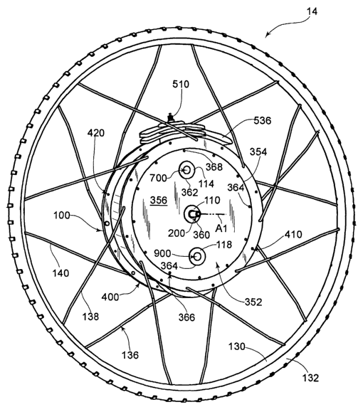
With reference to Fig. 2, the hub motor 100 is substantially located at the
center of the wheel 14.
The hub motor 100 may define a first axis A1 about which the hub motor 100 and
the entire wheel 14
rotates. The hub motor 100 may be provided with an axle assembly 200 about
which the hub motor 100
rotates.
With reference to Figs. 3-6, the axle assembly 200 may take a generally
cylindrical form having a
variety of features incorporated therewith. The axle assembly 200 is provided
with a first end 202 and an
oppositely disposed second end 204. The first end 202 may be provided with
threads 210 formed
therein. The axle assembly first end 202 may be provided with a first shoulder
212 at a point of
termination of the threads 210. The axle assembly 200 may be further provided
with a first surface 214
located between the first shoulder 212 and a first protrusion 216. The first
surface 214 may be formed
substantially cylindrical and may be concentric with the first axis A1. The
first protrusion 216 may extend
radially away from the first axis A1. The first protrusion 216 may have a
first face 218 and an oppositely
disposed second face 220, both of which may extend perpendicular from the
first axis A1. The first face
218 may be facing the first distal end 202, while the second face 220 may be
facing the second distal end
204. The axle assembly 200 may be further provided with a second surface 230.
The second surface
230 may originate at the first protrusion second face 220 and terminate at a
second protrusion 236. The
second protrusion 236 may extend radially away from the first axis A1. The
second protrusion 236 may
have a first face 238 and an oppositely disposed second face 240, both of
which may extend
perpendicular from the first axis A1. The first face 238 may be facing the
first distal end 202, while the
second face 240 may be facing the second distal end 204. The axle assembly 200
may be further
provided with a third surface 250. The third surface 250 may originate at the
second protrusion second
face 240 and terminate at a second shoulder 252. The third surface 250 may be
formed substantially
cylindrical and may be concentric with the first axis A1. The second shoulder
252 may extend
perpendicular from the first axis A1 and may be facing the second distal end
204. The axle assembly 200
may be further provided with a fourth surtace 260. The fourth surtace 260 may
originate at the second
shoulder 252 and terminate at a third shoulder 262. The fourth surface 260 may
be formed substantially
cylindrical and may be concentric with the first axis A1. The third shoulder
262 may extend perpendicular
from the first axis A1 and may be facing the second distal end 204. The axle
assembly second distal end
204 may be provided with threads 270 formed therein. The threads 270 may
originate at the third
shoulder 262 and terminate at the end of the axle assembly 200.
With reference to Fig. 5, an exemplary embodiment of the axle assembly 200 is
shown in a cross-
sectional view taken across plan 5-5 (Fig. 4). The axle assembly 200 may be
provided with a first cavity
280 and a second cavity 282. The cavities 280, 282 may take the form of blind-
holes formed in the axle
assembly 200. The first cavity 280 may originate at the first distal end 202
and extend to a cavity plug
284. It should be noted that the cavity plug 284 may be an integral component
of the axle assembly 200
-4-
CA 02486032 2004-11-15
WO 03/098039 PCT/US03/15547
or alternatively, an independent component provided with the axle assembly
200. The second cavity 282
may originate at the second distal end 204 and extend to the cavity plug 284.
With reference to Fig. 6, the axle assembly 200 may be further provided with a
pair of starter
holes 286. The pair of starter holes 286 may include a first starter hole 288
(Fig. 4) and a second starter
hole 290. The starter holes 286 may be formed in the second surface 230,
thereby allowing for
mechanical communication between the second surface 230 and the second cavity
282. The axle
assembly 200 may be further provided with a pair of gearing holes 292. The
pair of gearing holes 292
may include a first gearing hole 294 (Fig. 4) and a second gearing hole 296.
The gearing holes 292 may
be formed in the first surface 214, thereby allowing for mechanical
communication between the first
surface 214 and the second cavity 282. The axle assembly 200 may be further
provided with an
overdrive cover hole 298. The overdrive cover hole 298 may be formed in the
axle assembly 200 and
may be formed in the cavity plug 284. The axle assembly 200 may be further
provided with a plurality of
fuel holes 300, such as fuel holes 302, 304, 306, 308. The fuel holes 300 may
be formed in the axle
assembly 200 such that fluid communication may exist between the first surface
214 and the first cavity
280.
With reference to Fig. 4, the axle assembly 200 may be further provided with a
first starter mount
310 and a second starter mount 320. The first starter mount 310 may take the
form of a cylindrical hole
defining a second axis A2, the second axis A2 may be parallel to the first
axis A1. The second starter
mount 320 may take the form of a cylindrical hole defining a third axis A3,
the third axis A3 may be
parallel to the first axis A1 and the second axis A2. The starter mounts 310,
320 may be formed through
the first protrusion 216 and the second protrusion 236. Furthermore, the
starter mounts 310, 320 may be
formed into, but not completely through the portion defined by the third
surface 250.
With reference to Fig. 2, the hub motor 100 may be provided with a pair of
covers 350. The pair
of covers 350 may include a first cover 352 and a second cover 372 (Fig. 7).
The first cover 350 may
take the form of a disk having a generally circumferential edge 354. The first
cover 352 may be provided
with a first face 356 and an oppositely disposed second face 358. The
circumferential edge 354, the first
face 356 and the second face 358 may define the disk-like configuration of the
first cover 352. Bearing
mounts may be formed in the first cover 352, such as a first bearing mount
360. The first bearing mount
360 may be located at the center of the first cover 352. The first cover 352
may be provided with as
second bearing mount 362 and a third bearing mount 364. The second bearing
mount 362 may be
formed at a first distance D1 (Fig. 35) from the first bearing mount 360. In
one exemplary embodiment,
the first distance D1 may be about 2.88 inches. The third bearing mount 364
may be formed at a second
distance D2 (Fig. 35) from the first bearing mount 360. In one exemplary
embodiment, the second
distance D2 may be about 2.75 inches. Furthermore, the bearing mounts 360,
362, 364 may take the
form of holes through the first cover 352 thereby extending from the first
face 356 to the second face 358.
The first cover 352 may be further provided with a plurality of attachment
holes 366 such as a first
attachment hole 368. The first attachment hole 368 may be formed in-line with
the bearing mounts 360,
362, 364.
With reference to Fig. 7, the second cover 372 may take the form of a disk
having a generally
circumferential edge 374. The second cover 372 may be provided with a first
face 376 and an oppositely
disposed second face 378 (Fig. 38). The circumferential edge 374, the first
face 376 and the second face
-5-
CA 02486032 2004-11-15
WO 03/098039 PCT/US03/15547
378 may define the disk-like configuration of the second cover 372. Bearing
mounts may be formed in
the second cover 372, such as a fourth bearing mount 380. The fourth bearing
mount 380 may be
located at the center of the second cover 372. The second cover 372 may be
provided with as fifth
bearing mount 382 and a sixth bearing mount 384. The fifth bearing mount 382
may be formed at a third
distance D3 from the fourth bearing mount 380. In one exemplary embodiment,
the third distance D3
may be about 2.88 inches. The sixth bearing mount 384 may be formed at a
fourth distance D4 from the
fourth bearing mount 380. In one exemplary embodiment, the fourth distance D4
may be about 2.75
inches. Furthermore, the bearing mounts 380, 382, 384 may take the form of
holes through the second
cover 372 thereby extending from the first face 376 to the second face 378.
The second cover 372 may
be further provided with a plurality of attachment holes 386 such as a first
attachment hole 388. The first
attachment hole 382 may be formed in-line with the bearing mounts 380, 382,
384.
With reference to Figs. 8-12, the hub motor 100 may be provided with a hub
400. The hub 400
may define a fourth axis A4. The hub 400 may be provided with a generally
cylindrical member 402 that
may be located concentric to the forth axis A4. The cylindrical member 402 may
include an external
cylindrical face 403 and an oppositely disposed internal cylindrical face 405.
With reference to Fig. 8, the
hub 400 may be provided with a first face 404 and an oppositely disposed
second face 406. The
cylindrical member 402 may be generally formed between the first face 404 and
the second face 406.
The hub first face 404 may be provided with a plurality of spoke holes 410,
such as spoke holes 412, 414,
416, 418. The spoke holes 410 may be formed equidistant from the fourth axis
A4 and equally spaced
between each other. The hub second face 406 may be provided with a plurality
of spoke holes 420, such
as spoke holes 422, 424, 426, 428. The spoke holes 420 may be formed
equidistant from the fourth axis
A4 and equally spaced from each other.
With continued reference to Fig. 8, the hub 400 may be further provided with a
first flange 440
and an oppositely disposed second flange 480.
With reference to Fig. 9, the first flange 440 may be formed as a protrusion
on the inside surface
of the cylindrical member 402. The first flange 440 may be provided with a
first face 442, an oppositely
disposed second face 444 (Fig. 8) and an edge 446. The first flange 440 may be
provided with a groove
450 formed in the first face 442. The first flange 440 may be provided with a
plurality of threaded holes
460, such as threaded holes 462, 464, 466. The threaded holes 460 may be
formed equidistant from the
fourth axis A4 and equally spaced from each other.
With reference to Fig. 8, the second flange 480 may be formed as a protrusion
on the inside
surface of the cylindrical member 402. The second flange 480 may be provided
with a first face 482, an
oppositely disposed second face 484 and an edge 486. The second flange 480 may
be provided with a
groove 490 (Fig. 12) formed in the first face 482. The second flange 480 may
be provided with a plurality
of threaded holes 492, such as threaded holes 494 (Fig. 12), 496, 498. The
threaded holes 492 may be
formed equidistant from the fourth axis A4 and equally spaced from each other.
With reference to Fig. 10, the hub 400 may be provided with an engine 500.
Although the engine
500 is shown and described herein as a two-stroke engine, it is to be
understood that other types of
engines may be employed. Other types of engines include, but are not limited
to, diesel engines, rotary
engines and four-stroke engines. In the event that the four-stroke engine is
utilized, at least two valves
may be actuated to control the flow of combustible gases and exhaust gases.
The engine 500 may be
-6-
CA 02486032 2004-11-15
WO 03/098039 PCT/US03/15547
formed on the outside surface of the cylindrical member 402. The engine 500
may be formed.directly on
the cylindrical member 402, or alternatively may be removably attached
thereto. The engine 500 may be
located on the external cylindrical face 403; such placement may allow the
engine 500 to be exposed to
air (flowing there past) to cool the engine 500. The engine 500 may have a
combustion chamber 530
(Fig. 12) taking the form of a cylinder 504 having one end thereof closed. The
closed end of the engine
500 may be referred to herein as the head 502. The engine head 502 may be
provided with a threaded
hole 508 capable of receiving a sparkplug 510 (Fig. 2).
With reference to Fig. 11, the engine cylinder 504 may define a fifth axis A5.
In one exemplary
embodiment, the fifth axis A5 may be formed perpendicular to the fourth axis
A4. The engine cylinder
504 may be provided with a plurality of fins 520, such as fins 522, 524. The
fins 520 may be formed on
the engine cylinder 504.
With reference to Fig. 12, the engine combustion chamber 530 may be provided
with an intake
port 532 and an exhaust 534 (Fig. 11). In one exemplary embodiment, the intake
port 532 and the
exhaust 534 (Fig. 11) may be configured in a manner typical for two-stroke
engines. The hub motor 100
may be further provided with a muffler 536 (Fig. 2). The muffler 536 may be
attached to the engine
exhaust 534. In one exemplary embodiment, the exhaust 534 may be configured
such that it defines a
substantially long chamber that 'wraps' radial around the hub cylindrical
member 402.
With continued reference to Fig. 12, the hub 400 may be provided with a
counterbalance 550.
The counterbalance 550 may be formed on the outside surface of the hub
cylindrical member 402. The
counterbalance 550 may be provided with a first face 552 and an oppositely
disposed second face 554.
The counterbalance 550 may also be provided with a radial member 556. The
radial member 556 may
be attached to the first and second faces 552, 554. In one exemplary
embodiment, the counterbalance
550 may be removably attached to the hub cylindrical member 402. With
reference to Fig. 9, the
counterbalance 550 may define a fifth distance D5, the fifth distance D5 may
be the radius of curvature of
the radial member 556. In one exemplary embodiment, the fifth distance D5 may
be about 5.0 inches.
The vertex of a circle defined by the radial member 556 (having the radius of
the fifth distance D5) may
be located at a sixth distance D6 from the center of the hub 400 defined by
the fourth axis A4. In one
exemplary embodiment, the sixth distance D6 may be about 2.75 inches. With
reference to Fig. 12, the
counterbalance 550 may also define a seventh distance D7, the seventh distance
D7 may be the
dimension between the insides of the counterbalance first and second faces
552, 554. In one exemplary
embodiment, the seventh distance D7 may be about 0.50 inches.
With reference to Figs. 13-15, the hub motor 100 may be provided with a piston
600. The piston
600 may be provided with a top 602 and a skirt 604. The piston 600 may define
a sixth axis A6 located at
the center of the skirt 604. The top 602 may integrally formed with the skirt
604. The skirt 604 may be
provided with a groove 606 formed near the top 602 of the piston 600. The
piston 600 may be further
provided with a clevis pin hole 610 extending there through. With reference to
Fig. 14, the clevis pin hole
610 may define a seventh axis A7. In one exemplary embodiment, the seventh
axis A7 may be
perpendicular to the sixth axis A6. The piston 600 may be further provided
with an exhaust vane 620 and
an oppositely disposed intake vane 622 (Fig. 15). The exhaust and intake vanes
620, 622 may be
formed on the skirt 604 at a location oppositely disposed from the top 602.
The piston 600 may be further
_7_
CA 02486032 2004-11-15
WO 03/098039 PCT/US03/15547
provided with a first stabilizer 630 and an-oppositely disposed second
stabilizer 632. The stabilizers 630,
632 may be formed on the skirt 604 at a location oppositely disposed from the
top 602.
With reference to Fig. 16, the hub motor 100 may be provided with a crank arm
650. The crank
arm 650 may be provided with a first hole 652 and an oppositely disposed
second hole 654. The first
hole 652 may be separated from the second hole 654 by a thirteenth distance
D13. In one exemplary
embodiment, the thirteenth distance D13 may be about 2.0 inches.
With reference to Figs. 17-20, the hub motor 100 may be provided with an input
assembly 700.
The input assembly 700 may be provided with a crankshaft 702 that may include
a first portion 704 and a
second portion 706. The crankshaft first potion 704 may be separated from (but
mechanically connected
to) the crankshaft second portion 706 by a crank assembly 720. The crank
assembly 700 may include a
first crank 722 and a second crank 724. The crank assembly 700 may further
include a crank pin 730.
The first crank 722 may be attached to, or integrally formed with, the
crankshaft first portion 704. The
crank pin 730 may be attached to, or integrally formed with, the first crank
722. The second crank 724
may be attached to, or integrally formed with, the crank pin 730. The
crankshaft second portion 706 may
be attached to, or integrally formed with, the second crank 724. With
reference to Fig. 18, the crankshaft
702 may define an eighth axis A8 located at the center thereof. The crank pin
730 may define a ninth
axis A9 located at the center thereof. In one exemplary embodiment, the eighth
axis A8 may be parallel
to the ninth axis A9 and may be separated by an eighth distance D8. In one
exemplary embodiment, the
eighth distance D8 may be about 0.375 inches. With reference to Fig. 19, the
input assembly 700 may be
provided with a first gear 740. The first gear 740 may be provided with a
plurality of teeth 742 formed in
the outermost perimeter thereof. The first gear 740 may be attached to the
crankshaft first portion 704.
In one exemplary embodiment, the first gear 740 may be a spur gear having a
twenty-degree pressure
angle and a diametrical pitch of twelve teeth per inch; the gear 740 may have
an effective diameter of one
inch. With reference to Fig. 20, the input assembly second crank 724 may be
provided with a blind hole
750. The blind hole 750 may take the form of a blind hole formed in the input
assembly second crank
724.
With reference to Fig. 21, the hub motor 100 may be provided with a first gear
assembly 800.
The first gear assembly 800 may define a tenth axis A10. The first gear
assembly 800 may be provided
with a second gear 810 and a third gear 860. The second gear 810 may be
provided with a first face 812
and an oppositely disposed second face 814. The second gear 810 may be
provided with a plurality of
teeth 816 formed on the outermost perimeter thereof.
With reference to Fig. 22, the second gear first surface 812 may be provided
with an overrun
clutch 820. The overrun clutch 820 may be provided with an inner bearing
surface 822. In one
exemplary embodiment, the inner bearing surface 822 may be formed with a
substantially cylindrical
profile that is equidistant from the tenth axis A10. The inner bearing surtace
822 may be interrupted by a
plurality of pin detents 830, such as pin detent 832. Pin detent 832 may be
provided with a first end 834
and an oppositely disposed second end 836. The pin detent first end 834 may
define a ninth distance
D9. The pin detent second end 836 may define a tenth distance D10. In one
exemplary embodiment, the
ninth distance D9 may be greater than the tenth distance D10; it is noted that
the relationship between
the ninth and tenth distances D9, D10 may be reversed depending on overrunning
characteristics that are
required according to the direction of rotation of the wheel 16. In one
exemplary embodiment, the ninth
_g_
CA 02486032 2004-11-15
WO 03/098039 PCT/US03/15547
distance D9 may be about 0.135 inches, while the tenth distance D10 may be
about 0.110 inches. The
overrun clutch 820 may be provided with a bearing face 840; the bearing face
840 may be substantially
perpendicular to the tenth axis A10. With reference to Fig. 23, the first gear
assembly 800 may be
provided with a protrusion 850 formed on the second gear second face 814. The
protrusion 850 may be
provided with a first face 852 and an oppositely disposed second face 854.
Additionally, the protrusion
850 may be provided with a hole 856 there through. The protrusion first face
852 may be located on the
same plane as the overrun clutch bearing face 840 and the second gear second
face 814. In one
exemplary embodiment, the second gear 810 may be a spur gear having a twenty-
degree pressure angle
and a diametrical pitch of twelve teeth per inch; the second gear 810 may have
an effective diameter of
4.75 inches.
With reference to Figs. 23 and 24, the third gear 860 may be provided with a
first face 862 and an
oppositely disposed second face 864. The third gear 860 may be provided with a
plurality of teeth 866
formed on the outermost perimeter thereof. The third gear 860 may also be
provided with a hole 868
(Fig. 23) there through. In one exemplary embodiment, the third gear first
face 862 may be located on
the same plane as the first gear assembly protrusion second face 854. In one
exemplary embodiment,
the third gear 860 may be press-fit onto a protrusion (not shown) formed on
the second gear 810 due to
manufacturing considerations. In one exemplary embodiment, the third gear 860
may be a spur gear
having a twenty-degree pressure angle and a diametrical pitch of twelve teeth
per inch; the third gear 860
may have an effective diameter of one inch.
With reference to Fig. 22, the first gear assembly 800 may be provided with a
plurality of holes
890, such as holes 892, 894. The plurality of holes 890 may reduce the overall
weight of the first gear
assembly 800.
With reference to Figs. 25 and 26, the hub motor 100 may be provided with a
second gear
assembly 900. The second gear assembly 900 may be provided with a shaft 902
defining an eleventh
axis A11. The second gear assembly 900 may be further provided with a fourth
gear 910 and a fifth gear
930. The fourth gear 910 may be provided with a first face 912 and an
oppositely disposed second face
914. The fourth gear 910 may be provided with a plurality of teeth 916 formed
on the outermost
perimeter thereof. The fourth gear 910 may be fixedly attached to the shaft
902 in any one of a number
of ways, such as with a setscrew (not shown) or with a press-fit. In one
exemplary embodiment, the
fourth gear 910 may be a spur gear having a twenty-degree pressure angle and a
diametrical pitch of
twelve teeth per inch; the fourth gear 910 may have an effective diameter of
about 4.50 inches.
With reference to Fig. 25, the second gear assembly fourth gear 910 may be
provided with a
plurality of holes 918, such as holes 920, 922. The plurality of holes 918 may
reduce the overall weight of
the second gear assembly 900.
With reference to Fig. 26, the second gear assembly fifth gear 930 may be
provided with a first
face 932 and an oppositely disposed second face 934. The fifth gear 930 may be
provided with a
plurality of teeth 936 formed on the outermost perimeter thereof. The fifth
gear 930 may be fixedly
attached to the shaft 902 in any one of a number of ways, such as with a
setscrew (not shown) or with a
press-fit. In one exemplary embodiment, the fifth gear 930 may be a spur gear
having a twenty-degree
pressure angle and a diametrical pitch of twelve teeth per inch; the fifth
gear 930 may have an effective
diameter of one inch.
_g_
CA 02486032 2004-11-15
WO 03/098039 PCT/US03/15547
With reference to Figs. 27-31, the hub motor 100 may be provided with a third
gear assembly
1000. The third gear assembly 1000 may define a twelfth axis A12. The third
gear assembly 1000 may
be provided with a sixth gear 1010. The sixth gear 1010 may be provided with a
first face 1012 and an
oppositely disposed second face 1014. The sixth gear 1010 may be provided with
a plurality of teeth
1016 formed on the outermost perimeter thereof. With reference to Fig. 28, the
sixth gear first surface
1012 may be provided with an overrun clutch 1020. The overrun clutch 1020 may
be provided with an
inner bearing surface 1022. In one exemplary embodiment, the inner bearing
surface 1022 may be
formed with a substantially cylindrical profile that is equidistant from the
twelfth axis A12. The inner
bearing surface 1022 may be interrupted by a plurality of pin detents 1030,
such as pin detent 1032. Pin
detent 1032 may be provided with a first end 1034 and an oppositely disposed
second end 1036. The pin
detent first end 1034 may define an eleventh distance D11. The pin detent
second end 1036 may define
a twelfth distance D12. In one exemplary embodiment, the eleventh distance D11
may be greater than
the twelfth distance D12; it is noted that the relationship between the
eleventh and twelfth distances D11,
D12 may be reversed depending on overrunning characteristics that are
required. In one exemplary
embodiment, the eleventh distance D11 may be about 0.135 inches, while the
twelfth distance D12 may
be about 0.110 inches.
With reference to Fig. 29, the third gear assembly 1000 may be provided with a
starter protrusion
1040. The starter protrusion 1040 may take the form of a cylinder defining an
inside surface 1042 and an
outside surface 1044. The starter protrusion 1040 may be further provided with
a first face 1046 and an
oppositely disposed second face 1048. The starter protrusion 1040 may be
formed on the third gear
assembly 1000 such that the starter protrusion second surface 1048 resides in
the same plane as the
sixth gear first surface 1012. Furthermore, the starter protrusion inside
surface 1042 may be formed with
a substantially cylindrical profile that is equidistant from the twelfth axis
A12. The starter protrusion 1040
may be provided with a threaded hole 1060 extending from the outside surface
1044 to the inside surface
1042. In one exemplary embodiment, the sixth gear 1010 may be a spur gear
having a twenty-degree
pressure angle and a diametrical pitch of twelve teeth per inch; the sixth
gear 1010 may have an effective
diameter of 4.50 inches.
With reference to Fig. 31, the third gear assembly 1000 may be provided with a
plurality of holes
1018. The plurality of holes 1018 may reduce the overall weight of the third
gear assembly 1000.
With reference to Fig. 32, the hub motor 100 may be provided with an overdrive
cover 1100. The
overdrive cover 1100 may define a thirteenth axis A13. The overdrive cover
1100 may be provided with a
first face 1102 and an oppositely disposed second face 1104. The overdrive
cover 1100 may ~be provided
with a center hole 1110 located at the center thereof and extending from the
first face 1102 to the second
face 1104. The overdrive cover center hole 1110 may be formed with a
substantially cylindrical profile
that is equidistant from the thirteenth axis A13. The overdrive cover 1100 may
be further provided with an
attachment hole 1120. The attachment hole 1120 may be formed in-between the
first face 1102 and the
second face 1104. The attachment hole 1120 may also be formed with a threaded
portion for receiving a
setscrew (not shown) therein. The overdrive cover 1100 may be provided with a
first post 1130 and a
second post 1140. The first post 1130 may be formed on the second face 1104.
The first post 1130 may
take a substantially cylindrical form defining a central axis that is parallel
to the thirteenth axis A13. The
-lo-
CA 02486032 2004-11-15
WO 03/098039 PCT/US03/15547
second post 1140 may be formed on the second face 1104. The second post 1140
may take a
substantially cylindrical form defining a central axis that is parallel to the
thirteenth axis A13.
With reference to Fig. 33, the hub motor 100 may be provided with a plurality
of pads 1150, such
as pad 1152. Although only pad 1152 will be described herein, it is to be
understood that pad 1152 may
be substantially similar to the plurality of pads 1150. The pad 1152 may be
provided with a first face 1154
and an oppositely disposed second face 1156. The pad 1152 may be further
provided with an internal
surface 1160 and an external surface 1162. The pad 1152 may be provided with
an attachment hole
1158. The attachment hole 1158 may be formed in the pad 1152 and extend from
the first face 1154 to
the second face 1156. Furthermore, the attachment hole 1158 may define a
central axis that may be
substantially parallel to the internal and external surfaces 1160, 1162.
With reference to Fig. 34, the hub motor 100 may be provided with an overdrive
disk 1200. The
overdrive disk 1200 may define a fourteenth axis A14. The overdrive disk 1200
may be provided with a
first face 1202 and an oppositely disposed second face 1204. The overdrive
disk 1200 may be further
provided with an internal surtace 1206 and an oppositely disposed external
surface 1208. The overdrive
disk internal and external surfaces 1206, 1208 may be formed with a
substantially cylindrical profiles that
are, respectively, equidistant from the fourteenth axis A14.
With continued reference to Fig. 34, the hub motor 100 may also be provided
with a starter disk
1250 (which may be substantially similar to the overdrive disk 1200). The
starter disk 1250 may define a
fifteenth axis A15. The starter disk 1250 may be provided with a first face
1252 and an oppositely
disposed second face 1254. The starter disk 1250 may be further provided with
an internal surface 1256
and an oppositely disposed external surface 1258. The starter disk internal
and external surtaces 1256,
1256 may be formed with a substantially cylindrical profile that are,
respectively, equidistant from the
fifteenth axis A15. It is noted that although the starter disk 1250 and the
overdrive disk 1200 may take
similar forms, their actual dimensions may be adjusted as required.
Having provided exemplary members of one embodiment of the hub motor 100, a
description of
an exemplary assembled will now be provided.
With reference to Fig. 35, the hub motor 100 may be configured such that the
first cover 352 may
be rotationally attached to the axle assembly 200 by a first bearing 110. The
first bearing 110 may be
adjacent to both the first bearing mount 360 and the axle assembly first
surface 214 (Fig. 3). The second
cover 372 (Fig. 7) may be rotationally attached to the axle assembly 200 by a
second bearing 112 (Fig.
38). The second bearing 112 may be inserted into both the second cover first
bearing mount 380 (Fig. 7)
and the axle assembly fourth surface 260 (Fig. 3). With continued reference to
Fig. 35, the hub 400 may
be fixedly attached to the cover plates 350 by screws (not shown). The first
cover 352 may be attached
to the hub 400 via the plurality of attachment holes 366 and the plurality of
hub holes 460 (Fig. 9) through
which the screws may be inserted. The second cover 372 may be attached to the
hub 400 via the
plurality of attachment holes 386 and the plurality of hub holes 492 (Fig. 8)
through which screws may be
inserted. Attachment of the hub 400 to the cover plates 350 thereby allows the
hub 400 to rotate about
the axle assembly 200. It should be noted that the cover plates 350 may be
attached such that the
bearing mounts (e.g. first cover bearing mounts 360, 362, 364 and the second
cover bearing mounts 380,
382, 384) are in-line with the fifth axis A5 (Fig. 9).
-11-
CA 02486032 2004-11-15
WO 03/098039 PCT/US03/15547
With continued reference to Fig. 35, the hub motor 100 may be further
assembled by rotationally
attaching the input assembly 700 to the cover plates 350. The input assembly
700 may be rotationally
attached to the first cover plate 352 by a third bearing 114. The third
bearing 114 may be adjacent to
both the second bearing mount 362 and the crank assembly first portion 704
(Fig. 17). The input
assembly 700 may be rotationally attached to the second cover plate 372 by a
fourth bearing 116 (Fig.
38). The fourth bearing 116 may be adjacent to both the second bearing mount
382 (Fig. 7) and the
crank assembly second portion 706 (Fig. 17).
With continued reference to Fig. 35, the hub motor 100 may be further
assembled by rotationally
attaching the second gear assembly 900 to the cover plates 350. The second
gear assembly 900 may be
rotationally attached to the first cover plate 352 by a fifth bearing 118. The
fifth bearing 118 may be
adjacent to both the third bearing mount 364 and the second gear assembly
shaft 902 (Fig. 25). The
second gear assembly 900 may be rotationally attached to the second cover
plate 372 by a sixth bearing
120 (Fig. 38). The sixth bearing 120 may be adjacent to both the third bearing
mount 384 (Fig. 7) and the
second gear assembly shaft 902.
With reference to Fig. 36, the exemplary assembly of the hub motor 100 may be
further described
by showing the assembly with the covers 350 removed there from. As shown, the
axle assembly 200
provides a central member about which all the components may rotate (the
exception being driving
conditions when the third gear assembly and/or the first gear assembly may be
drivingly engaged to the
axle assembly 200, such situation will be described later herein). The
description of the exemplary
assembly of the hub motor 100 may continue by beginning at the piston 600 and
working through the
assembly to the axle assembly 200. The piston 600 may be assembled such that
the skirt 604 may be in
slidable contact with the engine cylinder combustion chamber 530. The piston
600 may be assembled
such that the top 602 may be movable adjacent to the engine head 502. The
piston 600 may be
assembled into the engine 500 such that the exhaust vane 620 (Fig. 13) may
slide across the engine
exhaust 534 (Fig. 11). The piston 600 may also be assembled into the engine
500 such that the intake
vane 622 (Fig. 15) may slide across the engine intake port 532 (Fig. 11). The
piston 600 may also be
assembled into the engine 500 such that the piston seventh axis A7 (Fig. 15)
is substantially parallel to
the hub fourth axis A4 (Fig. 12). The piston 600 may also be assembled into
the engine 500 such that the
piston sixth axis A6 (Fig. 15) is substantially parallel to the hub fifth axis
A5 (Fig. 12). Furthermore, a ring
(not shown) may be installed on the piston groove 606 (Fig. 13).
With reference to Fig. 37, the hub motor 100 may be further assembled by
attaching the crank
arm 650 to the piston 600. The assembly of the crank arm 650 to the piston 600
may occur by-way-of a
clevis pin (not shown). The clevis pin may contact the clevis pin hole 610 and
the crank arm first hole 652
(Fig. 16). Such attachment of the crank arm 650 to the piston 600 allow the
crank arm 650 to pivot about
the piston seventh axis A7.
With continued reference to Fig. 37, the hub motor 100 may be further
assembled by attaching
the crank arm 650 to the input assembly 700. Such attachment of the crank arm
650 to the input
assembly 700 may be a pivotable connection. The crank arm second hole 654
(Fig. 16) may contact the
crank pin 730 (Fig. 17). Such attachment of the crank arm 650 to the input
assembly 700 may allow the
crank arm 650 to pivot about the input assembly ninth axis A9 (Fig. 18).
-12-
CA 02486032 2004-11-15
WO 03/098039 PCT/US03/15547
The configuration of the hub motor 100 may allow for the input assembly first
gear 740 to be
drivingly engaged with the first gear assembly second gear 810. This
configuration may result in rotation
of the input assembly 700 being transferred to the first gear assembly 800 by-
way-of the first gear teeth
742 second gear teeth 816.
The hub motor 100 may be further assembled by rotationally attaching the first
gear assembly
800 to the axle assembly 200. As shown in Fig. 37, the assemblage of the first
gear assembly 800 and
the axle assembly 200 may result in the first gear assembly protrusion hole
856 (Fig. 23) and the first
gear assembly third gear hole 868 (Fig. 23) being in contact with the axle
assembly first surtace 214. The
first gear assembly 800 may be assembled with the axle assembly 200 such that
the first gear assembly
third gear second face 864 (Fig. 21) is adjacent to the axle assembly first
protrusion first face 218 (Fig. 3).
With reference to Fig. 38, the hub motor 100 may be further assembled such
that the second
gear assembly 900 is drivingly engaged with the first gear assembly 800. This
drivable engagement may
be provided by placing the first gear assembly third gear 860 into contact
with the second gear assembly
fourth gear 910. Such contact between the third gear 860 and the fourth gear
910 may occur by the third
gear teeth 866 contacting the fourth gear teeth 916. This contact of the teeth
866, 916 may render the
first gear assembly 800 drivable engaged with the second gear assembly 900.
With continued reference to Fig. 38, the hub motor 100 may be further
assembled such that the
third gear assembly 1000 is drivingly engaged with the second gear assembly
900. This drivable
engagement may be provided by placing the second gear assembly fourth gear 930
into contact with the
third gear assembly fifth gear 1010. Such contact between the fourth gear 930
and the fifth gear 1010
may occur by the fourth gear teeth 936 contacting the fifth gear teeth 1016.
This contact of the teeth 936,
1016 may render the second gear assembly 900 drivably engaged with the third
gear assembly 1000.
The hub motor 100 may be further assembled by rotationally attaching the third
gear assembly
1000 to the axle assembly 200. As shown in Fig. 38, the assemblage of the
third gear assembly 1000
and the axle assembly 200 may result in the third gear assembly inner bearing
surface 1022 (Fig. 28)
being in contact with the axle assembly third surface 250 (Fig. 3).
The third gear assembly 1000 may be assembled with the axle assembly 200 such
that the third
gear assembly pin flange 1038 (Fig. 28) is essentially coplanar with the axle
assembly third shoulder 262
(Fig. 3). Furthermore, the starter protrusion second face 1048 (Fig. 29) may
be coplanar with the axle
assembly second protrusion second face 240 (Fig. 3). The third gear assembly
1000 may be rotationally
attached to the axle assembly 200 via the starter disk 1250 (Fig. 34). The
starter disk 1250 may be into
the assembly such that the starter disk external surface 1258 contacts the
third gear assembly starter
protrusion inside surface 1042 (Fig. 29). The starter disk 1250 may be further
assembled such that the
starter disk second surface 1254 (Fig. 29) contacts the axle assembly second
protrusion first face 238
(Fig. 3). The starter disk 1250 may be fixedly attached to the third gear
assembly 1000 by a setscrew
(not shown) inserted through the third gear assembly threaded hole 1060. The
setscrew may be
tightened such that the starter disk 1250 may not rotate with respect to the
third gear assembly 1000.
The starter disk 1250 may allow for rotational attachment of the third gear
assembly 1000 to the axle
assembly 200 about the first axis A1, while limiting non-conforming
translation along the first axis A1.
With reference to Fig. 37, the first gear assembly overrun clutch 820 may be
assembled by
placing a plurality of pins 824 into the plurality of pin detents 830, such as
pin 826 being placed into pin
-13-
CA 02486032 2004-11-15
WO 03/098039 PCT/US03/15547
detent 832. The description provided herein will be directed to the single pin
826 and pin detent 832, it
should be understood that this description is adequate for describing the
plurality of pins 824 and pin
detents 830. The pin 826 may be placed in pin detent 832 such that the pin 826
is captured between the
pin detent 832 and the overdrive disk 1200. It should be noted that in one
exemplary embodiment, the
overdrive disk first face 1202 may be positioned adjacent to the first gear
assembly first face 812. Such
adjacent placement of the overdrive disk 1200 to the first gear assembly 800
may result in the overdrive
disk external surtace 1208 being slidably adjacent to the first gear assembly
inner bearing surtace 822.
Furthermore this adjacent placement may also place the overdrive disk second
face 1204 (Fig. 34)
adjacent to the first gear assembly bearing face 840 (Fig. 22). This captured
placement of the pin 826
may allow the pin to exert contact force on both the pin detent 832 and the
overdrive disk external surtace
1208 if the pin 826 is positioned near the pin detent second end 836. However,
if the pin 286 is
positioned near the pin detent first end 834, the pin 826 does not exert
substantial forces on the pin
detent 832 and the overdrive disk external surface 1208. In one embodiment,
the assembly may be
provided with a small spring (not shown) that urges the pin 826 away from the
pin detent first end 834. It
should be apparent to those skilled in the art that this overrun clutch 820
may allow rotational movement
between the first gear assembly 800 and the overdrive disk 1200 when rotating
in one direction, however
not allowing rotational movement when rotating in the opposite direction.
With reference to Fig. 39, the hub motor 100 may be further assembled by
providing an overdrive
1270. The overdrive 1270 may be assembled by placing a pair of pads 1272
between the axle assembly
200 and the overdrive disk 1200. It is noted that the assemblage of one pad
will be provided, it should be
understood that the second pad may be assembled in a similar manner. Pad 1152
may be assembled
with the first gear assembly 800 and the overdrive disk 1200 such that the pad
first face 1154 (Fig. 33)
may be adjacent to the first gear assembly bearing face 840 (Fig. 22).
Furthermore, the pad internal
surface 1160 may be adjacent to the axle assembly first surface 214, and the
pad external surface 1162
may be adjacent to the overrun clutch internal surtace 1206.
With continued reference to Fig. 39, the overdrive 1270 may be further
assembled by installing
the overdrive cover 1100 to capture the pins 824 and the pads 1272. The
overdrive cover 1100 may be
positioned such that the center hole 1110 thereof contacts the axle assembly
first surface 214. The
overdrive cover 1100 may be positioned such that the overdrive cover second
face 1104 may contact the
overdrive disk first face 1202, the first gear assembly first face 812 (Fig.
37), and the pad second face
1156. Furthermore, the overdrive cover first post 1130 may be placed into
contact with the pad hole
1158. The second pad of the pair of pads 1272 may be captured in a similar
manner by the overdrive
cover second post 1140. The overdrive cover 1100 may be positioned on the axle
assembly 200 such
that the overdrive cover attachment hole 1120 aligns with the axle assembly
overdrive cover hole 298.
An attachment pin (not shown) may be placed into the overdrive cover
attachment hole 1120 and
positioned through the axle assembly overdrive cover hole 298 to secure the
overdrive cover 1100 and all
parts interfaced therewith. This attachment pin may be anchored into position
by a pair of setscrews (not
shown) threaded into the overdrive cover attachment hole 1120.
With continued reference to Fig. 39, the third gear assembly overrun clutch
1020 may be
assembled by placing a plurality of pins 1024 into the plurality of pin
detents 1030 (Fig. 29), such as pin
1026 being placed into pin detent 1032 (Fig. 28). The description provided
herein will be directed to the
-14-
CA 02486032 2004-11-15
WO 03/098039 PCT/US03/15547
single pin 1026 and pin detent 1032 (Fig. 18), it should be understood that
this description is adequate for
describing the plurality of pins 1024 and pin detents 1030. The pin 1026 may
be placed in pin detent
1032 (Fig. 29) such that the pin 1026 is captured between the pin detent 1032
and the pin flange 1038
(Fig. 29). The pin 1026 may be further captured by the axle assembly second
protrusion second face 240
(Fig. 3) and the axle assembly third surface 250. Such captured placement of
the pin 1026 may allow for
rotationally sliding contact of the third gear assembly inner bearing surface
1022 (Fig. 28) to the axle
assembly third surface 250. This captured placement of the pin 1026 may allow
the pin to exert contact
force on both the pin detent 1032 (Fig. 28) and the axle assembly third
surface 250 (Fig. 3) if the pin 1026
is positioned near the pin detent second end 1036. However, if the pin 1026 is
positioned near the pin
detent first end 1034 (Fig. 28), the pin does not exert substantial forces on
the pin detent 1032 and the
axle assembly third surface 250. In one embodiment, the assembly may be
provided with a small spring
(not shown) that urges the pin 1026 away from the pin detent first end 1034.
It should be apparent to
those skilled in the art that this overrun clutch 1020 may allow rotational
movement between the third
gear assembly 1000 and axle assembly 200 when rotating in one direction,
however not allowing
rotational movement when rotating in the opposite direction.
With continued reference to Fig. 39, the hub motor 100 may be further
assembled by providing a
starter 1300 between the axle assembly 200 and the starter disk 1250. The
starter 1300 may be provided
with a pair of pads 1302, such as pad 1304. It is to be understood that pad
1304 may be substantially
similar to pad 1152. It is noted that the assemblage of one pad 1304 (also
referred to herein as pad
1152) will be provided, it should be understood that the second pad may be
assembled in a similar
manner. Pad 1152 may be positioned between the starter disk 1250 and the axle
assembly 200 such
that the pad external surface 1162 may be adjacent to the starter disk inside
surface 1256. Furthermore,
the pad internal surface 1160 (Fig. 33) may be adjacent to the axle assembly
second surtace 230 (Fig. 3).
This placement may result in the pad first face 1154 (Fig. 33) being adjacent
to the axle assembly second
protrusion first face 238 (Fig. 3). This placement may also result in the pad
second face 1156 being
adjacent to the axle assembly first protrusion second face 220 (Fig. 3).
Furthermore, the pad 1152 may
be hingedly attached to the axle assembly 200 by a starter pin (not shown).
The starter pin may be
positioned in the first starter mount 310 (Fig. 4) and the pad hole 1158 (Fig.
33). Such hinged attachment
may allow for movement of the pad external surtace 1162 away from the first
axis A1, while inhibiting
rotation of the pad 1152 about the first axis A1.
With reference to Fig. 40, the hub motor 100 may be provided with a
starter/overdrive selector
assembly 1350. The starter/overdrive selector assembly 1350 may be provided
for actuation of the
starter pads 1302 and/or the overdrive pads 1272. The starter/overdrive
selector assembly 1350 may be
provided with a rod 1360. With reference to Fig. 41, the rod 1360 may define a
sixteenth axis A16. The
rod 1360 may define a first distal end 1362 and an oppositely disposed second
distal end 1364. The rod
1360 may take a substantially cylindrical form defined by a surface 1366, the
rod surface 1366 may have
features formed therein. The rod 1360 may be provided with a first ramp 1370
and a second ramp 1380.
The first ramp 1370 may be formed in the rod surface 1366 somewhat near the
second distal end 1364.
The second ramp 1380 may be formed in the rod surface 1366 between the first
ramp 1370 and the
second distal end 1362. The first ramp 1370 may be provided with a first
surface 1372 and a second
surface 1374. The first surface 1372 may take a substantially cylindrical form
that may be parallel to the
-15-
CA 02486032 2004-11-15
WO 03/098039 PCT/US03/15547
sixteenth axis A16. The second surface 1374 may take the form of a portion of
a cone, of which the
vertex may be located on the sixteenth axis A16. The small end of the conical
second surface 1374 may
intersect the first sun'ace 1372. The large end of the conical second surface
1374 may intersect the rod
surface 1366.
The second ramp 1380 may be provided with a first surface 1382 and a second
surface 1384.
The first surface 1382 may take a substantially cylindrical form that may be
parallel to the sixteenth axis
A16. The second surface 1384 may take the form of a portion of a cone, of
which the vertex may be
located on the sixteenth axis A16. The small end of the conical second surface
1384 may intersect the
first surface 1382. The large end of the conical second surface 1384 may
intersect the rod surtace 1366.
The rod 1360 may be further provided with a connector 1390 formed near the
first distal end 1362.
With reference to Fig. 40, the starter/overdrive selector assembly 1350 may be
further provided
with a cable 1394. The cable 1394 may be attached to the rod connector 1390
and a selector 1400 (Fig.
1). The starter/overdrive selector assembly 1350 may be provided with a pair
of starter actuator balls
1410 and a pair of overdrive actuator balls 1412. Additionally, the
starter/overdrive selector assembly
1350 may be provided with a return spring 1392 (Fig. 40). The
starter/overdrive selector assembly 1350
may be assembled with the axle assembly 200 by placing the rod 1360 into the
axle assembly 282
second cavity. The starter actuator balls 1410 may be place in the starter
holes 286. The starter actuator
balls 1410 may be captured by the starter holes 286, the rod first ramp first
surface 1372 (Fig. 41) and the
pair of starter pads 1300. The overdrive actuator balls 1412 may be placed in
the gearing holes 292.
The second pair of actuator balls 1412 may be captured by the gearing holes
292, the rod second ramp
first surface 1382 (Fig. 41) and the pair of overdrive pads 1272. The return
spring may urge the rod 1360
such that the rod second distal end 1364 (Fig. 41) may be adjacent to the
cavity plug 284. When the rod
1360 is urged by the return spring 1392, the starter/overdrive selector
assembly 1350 may be placed into
a first condition. During this first condition, the first ramp first surface
1372 may be adjacent to the starter
holes 286. With the first ramp first surface 1372 adjacent to the starter
holes 286, the starter actuator
balls 1410 may not be place under compressive forces. Therefore, the starter
pads 1300 may not be
exerting substantial force on the third gear assembly starter disk 1350 (Fig.
39). During this first
condition, the second ramp first surface 1382 may be adjacent to the gearing
holes 292. With the second
ramp first surface 1382 adjacent to the gearing holes 292, the overdrive
actuator balls 1412 may not be
place under compressive forces. Therefore, the overdrive pads 1272 may not be
exerting substantial
force on the overdrive disk 1200.
When the rod 1360 is urged by the cable 1394, the starter/overdrive selector
assembly 1350 may
be placed into a second condition. During this second condition, the first
ramp second surface 1374 (Fig.
41) may be adjacent to the starter holes 286. With the first ramp second
surface 1374 adjacent to the
starter holes 286, the starter actuator balls 1410 may be place under
compressive forces. Therefore, the
starter pads 1300 may be exerting force on the third gear assembly starter
disk 1250 (Fig. 39). During
this second condition, the second ramp second surface 1384 may be adjacent to
the gearing holes 292.
With the second ramp second surface 1384 adjacent to the gearing holes 292,
the overdrive actuator
balls 1412 may be place under compressive forces. Therefore, the overdrive
pads 1272 may be exerting
substantial force on the overdrive disk 1200 (Fig. 39). It should be noted
that in one exemplary
embodiment, when the hub motor 100 is in the second condition, the third gear
assembly 1000 may be
-16-
CA 02486032 2004-11-15
WO 03/098039 PCT/US03/15547
fixedly (i.e. non-rotatably) attached to the axle assembly 200. Additionally,
in this exemplary second
condition, the overdrive disk 1200 may be fixedly (i.e. non-rotatably)
attached to the axle assembly 200.
With reference to Fig. 38, the hub motor 100 may be provided with a carburetor
1500. The
carburetor 1500 may be any one of a variety of carburetors such as, for
example, a diaphragm
carburetor, a needle-jet carburetor, or other metering device known to those
skilled in the art. As shown
in Fig. 38, a needle-jet carburetor 1500 may be provided with a connection
1502 (e.g. threads) for fixedly
attaching the carburetor 1500 to the axle assembly 200 (it is noted that the
axle assembly 200 is fixedly
attached to the bicycle 10, therefore the carburetor 1500 is fixedly attached
to the bicycle 10). The
carburetor 1500 may be further provided with an air passage 1510. The air
passage 1510 may originate
at an intake 1512. The air passage intake 1512 may be attached to an air
filter 1514. The filter 1514 may
be provided with an outlet to which an internal passage 1516 may be attached.
The internal passage
1516 may be attached to a mixing zone 1518. The mixing zone 1518 may be
attached to a check valve
1530, such as a reed valve. The check valve 1530 may be attached to the
threaded connection 1502.
With continued reference to Fig. 38, the carburetor 1500 may be further
provided with a fluid
passage 1540. The fluid passage 1540 originates at an intake 1542. The fluid
passage intake 1542 may
be attached to a jet 1544. The jet 1544 may be configured in the mixing zone
1518. It is noted that the
connections between components of the carburetor 1500 may be referred to
herein as being in 'fluid
communication' with each other. As used herein, the term fluid communication
means that air and/or fluid
may be transported between two areas (e.g. the engine may be in fluid
communication with the
carburetor). The carburetor may be further provided with a throttle plate
1550. The throttle plate 1550
may be configured such that flow of air through the air passage 1510 may be
selectively controlled. This
selective control of the air passage 1510 may be controlled via a throttle
cable 1560 to which the throttle
plate 1550 is attached. The throttle cable 1560 may be attached to a throttle
grip 1564 (Fig. 1).
With reference to Fig. 1, the hub motor 100 may be further provided with a
fuel tank 1600 the fuel
tank 1600 may be attached to the fluid passage intake 1542 (Fig. 38) via a
fuel line 1602.
With reference to Fig. 38, having provided a description of exemplary
components of the
carburetor 1500, a description of the transfer of fuel from the fuel tank 1600
to the engine 500 will now be
provided. Fuel, such as, for example, gasoline, hydrogen, ethanol, propane,
etc. may be stored in the
fuel tank 1600. The fuel may travel from the fuel tank 1600 through the fuel
line 1602 to the fluid passage
intake 1542. After entering the fluid passage intake 1542, the fuel may travel
to the jet 1544. At the jet
1544, the fuel may be mixed with air that is traveling through the air passage
1510 in the mixing zone
1518. It is noted that the air may be purified by the filter 1514 to remove
any contaminates therefrom.
This mixture of the air and the fuel in the mixing zone 1518 results in an
combustible air/fuel mixture.
This air/fuel mixture may also be referred to herein as a combustible mixture,
a combustible gas, or other
equivalents describing a mixture which is combustible.
In a process to be described later herein, the combustible mixture may travel
from the mixture
zone 1518 past the check valve 1530, and through the threaded connection 1502
and into the axle
assembly 200. The combustible mixture may travel from the axle assembly first
distal end 202, through
the first cavity 280 and to the fuel holes 300. Once the combustible mixture
travels to the fuel holes 300,
the mixture may enter an interior portion 102 of the hub motor 100.
-17-
CA 02486032 2004-11-15
WO 03/098039 PCT/US03/15547
With reference to Fig. 36, the hub motor interior portion 102 may be defined
as the area of the
hub motor 100 substantially encased by the covers 350 and the hub 400. It
should be noted that this
interior portion 102 may be substantially air-tight wherein a pressure may be
applied thereto and retained
for a duration of time. Additionally, this interior portion may be configured
such that it substantially retains
a vacuum as well as a pressure. A pair of o-rings (not shown) may be
positioned in the hub first flange
groove 450 and the hub second flange groove 590. This interior portion 102 may
receive the combustible
mixture from the carburetor 1500 via the fuel holes 300. This combustible
mixture may disperse
throughout the entire interior portion, thereby being 'available' at the
combustion chamber intake port 532
(Fig. 12). It is noted that as used herein, the term 'available' when
referenced to the combustible mixture
may mean that the combustible mixture is accessible in a substantial quantity
to allow for proper
operation of the engine 500.
The hub motor 100 may be provided with an ignition system 1650. Although
ignition systems are
known to those skilled in the art, one particular embodiment will now be
described. It is noted that this
exemplary embodiment is provided for illustrative purposes only and may be
modified or replaced
depending on performance objectives. The ignition system 1650 may be a Hall
Effect type wherein a
controller monitors the performance of the engine 500 and adjusts the spark of
the sparkplug 510
accordingly. The ignition system 1650 receives input that the piston 600 is
located at the uppermost
portion of the engine (i.e. the combustible media is fully compressed). This
input may be provided by a
mechanical point or a Hall Effect device sensing presence of a magnet located
in the input assembly
second crank blind hole 750 (Fig. 20). The ignition system 1650 sends
electricity to the sparkplug 510
that ignites the combustible media contained within the engine combustion
chamber 530. As part of this
ignition system 1650, electricity may be provided by a battery pack,
alternator or magneto.
With reference to Fig. 2, the wheel 14 may be assembled by providing the hub
motor 100 with a
rim 130, a tire 132, a tube 134 and a plurality of spokes 136, such as spokes
138, 140. The plurality of
spokes 136 may be utilized to attach the rim 130 to the hub 400. Such
attachment of the rim 130 to the
hub 400 may be accomplished by lacing the spokes 136 through the hub spoke
holes 410, 420. It should
be noted that if the engine 500 obstructs the spokes 136, the engine 500 may
have spoke clearance
grooves formed therein. The wheel 14 may be rotationally attached to the
bicycle 10 by fixedly attaching
the axle assembly 200 to the forks 18. This fixed attachment of the axle
assembly 200 to the forks 18
may utilize threaded nuts (not shown). A first nut may attach the axle
assembly first distal end 202 to the
first fork distal end mounting plate 54. A second nut may attach the axle
assembly second distal end 204
to the second fork distal end mounting plate 64.
Exemplary operation of the hub motor 100 will now be described. The operation
may result in a
number of conditions such as an off condition, a starting condition, an idling
condition and an operating
condition. The operating condition may be provided with at least a first
condition and a second condition.
The off condition of the hub motor 100 will now be described. During the off
condition, the hub
motor 100 doe not consume any fuel. In this condition, the third gear assembly
overrun clutch 1020 and
the first gear assembly overrun clutch 820 may allow for the hub motor 100 to
'overrun' the axle assembly
200. As used herein the term 'overrun' may be defined as a condition wherein a
first element is allowed
to rotate freely around a second element. In the case of the third gear
assembly overrun clutch 1020, the
third gear assembly 1000 may rotate freely about the axle assembly 200 (i.e.
the third gear assembly
-18-
CA 02486032 2004-11-15
WO 03/098039 PCT/US03/15547
1000 overruns the axle assembly 200). In the case of the first gear assembly
overrun clutch 820, the first
gear assembly 800 may rotate freely about the axle assembly 200. In this off
condition, the bicycle 10
may be used as a conventional transportation device by pedaling the cranks 40
and the hub motor 100
does not impart any forces on the forward movement.
The starting condition of the hub motor 100 will now be described. The process
of starting the
engine 500 may occur during when a user desires to bring the hub motor 100 to
the idling and/or
operating condition from the off condition. Assuming that the bicycle 10 is in
motion in the first direction
D1 (Fig. 1), during the starting condition, the starter/overdrive selector
assembly 1350 may be activated
(previously described herein as the starter/overdrive selector assembly second
condition). Activation of
the starter/overdrive selector assembly 1350 may result in the rod 1360
displacing the pair of starter
actuator balls 1410 away from the first axis A1. This displacement of the
starter actuator balls 1410 may
result in the starter pads 1302 inhibiting rotational movement of the third
gear assembly 1000 about the
axle assembly 200. This lack of rotational movement between the third gear
assembly 1000 and the axle
assembly 200 may also be refereed to herein as fixedly attaching the third
gear assembly 1000 to the
axle assembly 200. This attachment may result in rotational movement of the
hub motor 100 causing
movement of the piston 600. Such piston movement may result in the piston 600
reciprocating in the
engine 500 along the fifth axis A5. By reciprocating in the engine 500, the
piston compresses any
combustible mixture located in the engine 500. With compression of the
combustible mixture, the engine
500 may be started by providing a spark (unless the engine 500 is configured
in a diesel format). The
ignition system 1650 may provide this spark via the sparkplug 510. Once the
engine receives this spark,
the engine may be placed into the idling condition.
The idling condition of the hub motor 100 will now be described. During the
idling condition, the
hub motor 100 may be consuming fuel and therefore considered to be running. In
this idling condition,
the third gear assembly overrun clutch 1020 and the first gear assembly
overrun clutch 820 may allow for
the hub motor 100 to 'overrun' the axle assembly 200 (assuming that the
starter/overdrive selector
assembly is returned to the first condition; this condition may be referred to
herein as an underpowered
condition). Utilizing the third gear assembly overrun clutch 1020, the third
gear assembly 1000 may
rotate freely about the axle assembly 200. Utilizing the first gear assembly
overrun clutch 820, the first
gear assembly 800 may rotate freely about the axle assembly 200. This idling
condition allows the
engine 500 to be running, but not actually accelerating the bicycle 10.
The operating condition of the hub motor 100 will now be described. During the
operating
condition, the engine 500 accelerates the bicycle 10 by taking in clean
combustible mixture, compressing
the combustible mixture, igniting the combustible mixture (thereby creating a
spent mixture) and
exhausting the spent mixture. The process of igniting combustible mixtures is
well known in the art of
internal combustion engines, however a brief description will now be provided.
With reference to Fig. 36,
at the outset, the combustible mixture located in the hub interior portion 102
may be drawn into the
combustion chamber 530 through the intake port 532 (Fig. 12). The piston 600
may move in a second
direction D2 thereby compressing the combustible mixture in the combustion
chamber 530. At the top of
the stroke of the piston 600, the ignition system 1650 may send a signal to
the sparkplug 510. The
sparkplug 510 may ignite the compressed combustible mixture thereby moving the
piston 600 in a third
direction D3. This piston movement in the third direction D3 may impart a
force on the input assembly
-19-
CA 02486032 2004-11-15
WO 03/098039 PCT/US03/15547
700. Once the piston 600 passes the exhaust 534, the spent gas may be expelled
from the combustion
chamber 530 to the muffler 536. As the spent gas is expelled, the combustible
mixture is drawn into the
combustion chamber 530 through the intake port 532 (Fig. 12). The process
continues as required,
thereby providing rotation of the input assembly 700. Force applied to the
input assembly 700 may be
harnessed to cause rotation of the input assembly 700. This rotation of the
input assembly 700 may be
transmitted through the hub motor 100 to cause rotation of the hub motor 100.
Rotation of the hub motor
100 is mirrored by the rim 130 and tire 132. Rotation of the tire 132 urges
the bicycle 10 in the first
direction D1.
During the first operating condition, the hub motor 100 may be configured such
that the bicycle 10
may operate at relatively lower speeds. This relatively lower speed may
require that the relatively high
revolutions per minute (RPM) of the engine 500 be converted to the relatively
low revolutions per minute
of the wheel 14. In order to reduce the high RPMs of the engine 500 to the low
RPMs of the wheel 14,
the third gear assembly 100 may be drivingly engaged with the axle assembly.
Therefore, in the first
operating condition, the energy applied to the input assembly 700 by the
piston 600 may travel through
the first gear assembly 800 to the second gear assembly 900. The energy may be
further transferred
from the second gear assembly 900 to the third gear assembly 1000. In one
exemplary embodiment,
such transmission of energy may result in a reduction of the engine RPMs from
5000 RPM to 50 RPM
through a 100:1 reduction. This reduction may be accomplished through the
combination of the first,
second and third gear assemblies 800, 900, 1000.
During the second operating condition, the hub motor 100 may be configured
such that the
bicycle 100 may operate at relatively high speeds. This relatively high speed
may require that the
relatively high revelations per minute (RPM) of the engine 500 be converted to
the relatively higher
revolutions per minute (when compared to the first operating condition) of the
wheel 14. In order to
minimize the reduction of the high RPMs of the engine 500 to the higher RPMs
of the wheel 14, the first
gear assembly 800 may be drivingly engaged with the axle assembly 200.
Therefore, in the second
operating condition, the energy applied to the input assembly 700 may travel
to the first gear assembly
800. In one exemplary embodiment, such transmission of energy may result in a
reduction of the engine
RPMs from 2000 RPM to 333 RPM through a 6:1 reduction.
In both the first and second driving conditions, the first gear assembly
overrun clutch 820 and the
third gear assembly overrun clutch 1020 may serve to control the power input
of the engine 500. When
employed, the overrun clutches 820, 1020 allow the engine 500 to accelerate
the bicycle 10 in the first
direction D1, while substantially prohibiting deceleration in the first
direction D1. As such, the user my
pedal the bicycle 10 with the cranks 40 to either assist or solely-power the
bicycle 10.
For descriptive purposes only, an exemplary scenario will be provided. With
reference to Fig. 1, a
user (not shown) may be located on the bicycle 10. At the outset, the hub
motor 100 is in the off
condition. The user begins to ride the bicycle 10 in the first direction D1 by
pedaling the cranks 40.
Pedaling of the cranks 40 causes movement of the chain 42. Movement of the
chain 42 causes
counterclockwise CCW rotation of the rear wheel 16. The rotation of the rear
wheel 16 may cause
movement in the first direction D1. Movement of the rear wheel 16 is mirrored
by the frame 12 and the
front wheel 14. This movement of the front wheel 14 also causes
counterclockwise CCW rotation of the
front wheel 14.
-20-
CA 02486032 2004-11-15
WO 03/098039 PCT/US03/15547
Rotation of the front wheel 14 may allow for the user to invoke the starting
condition of the hub
motor 100. The user may desire to invoke the starting condition in order to
urge the hub motor 100 into
the operating condition so that the bicycle 10 may be propelled by the hub
motor 100. During this stating
condition, the user may select the starter/overdrive selector assembly
selector 1400 to place the
starter/overdrive selector assembly 1350 into the second condition. Such
activation of the selector 1400
may urge the cable 1394, thereby causing movement of the rod 1360. As
previously described
movement of the rod 1360 displaces the starter pads 1302, the third gear
assembly 1000 may become
temporarily fixedly attached to the axle assembly 200. By temporarily fixedly
attaching the third gear
assembly 1000 to the axle assembly 200, the gear assemblies 800, 900, 1000 may
begin to rotate with
respect to the hub 400 and the engine 500 attached thereto. The movement of
the gear assemblies may
cause the piston 600 to reciprocate in the engine 500 in a manner previously
described. This
reciprocation of the piston 600 acts as a 'fuel pump' that draws combustible
media from the carburetor
1500 (it should be noted that access to fuel is controlled by the users input
to the throttle grip 1564). In a
process previously described, the combustible media is introduced into the
combustion chamber 1530
and ignited by the ignition system 1650. As the piston 600 reciprocates, the
ignition of combustible media
adds energy to the hub motor 100.
The energy added to the hub motor 100 via the piston 600 is transferred to the
input assembly
700 in a manner previously described. This energy may be transferred to the
axle assembly 200 such
that the bicycle 10 accelerates in the first direction D1. Once the user
desires to maintain a speed in the
first direction D1, input of energy by the engine 500 may be reduced. This
reduction of input by the
engine 500 may be invoked through the users selection of the throttle grip
1564. With a reduction of the
combustible media input through the throttle grip 1564, the engine 100 may be
placed into the idling
condition. During this idling condition, the engine 500 may still be running,
however it is not contributing
to movement in the first direction D1. This idling condition may continue
until the user desires to
accelerate in the first direction D1, upon occurrence, for example, of a
straight section of road. To
accelerate, the user may activate the throttle grip 1564 to open the throttle
plate 1550. An increase in air
flowing through the air passage 1510 may also increase the flow of fuel from
the jet 1544. Increased flow
of air and fuel, may result in an increase in combustible media being
available for the engine 500. This
increased availability of combustible media may allow the engine 500 to
contribute more energy to the
hub motor 100. As this increased energy is imparted on the hub motor 100, the
third gear overrun clutch
820 may be urged into the condition wherein the axle assembly 200 is
substantially fixedly attached to the
third gear assembly 1000. With this fixed attachment, the bicycle 10 may begin
to accelerate in the first
direction D1. This process may continue indefinitely (so long as fuel reserves
exist) until the user desires
to place the hub motor into the off condition. Such activation may occur by
shutting off the supply of fuel
and/or shutting of the ignition system 1650.
If during the previously described operating condition the user desires to
travel at a higher
velocity in the first direction D1, the user may invoke the second driving
condition. By activating the
starter/overdrive selector assembly selector 1400, the user may cause the
overdrive pads 1272 to fixedly
attach the overdrive disk 1200 to the axle assembly 200. By fixedly attaching
the overdrive disk 1200 to
the axle assembly 200, the gearing ratio of the hub motor 100 may be
decreased. By decreasing the hub
motor gearing ratio, the bicycle 10 may be powered in the first direction D1
at an increased speed
-21-
CA 02486032 2004-11-15
WO 03/098039 PCT/US03/15547
because the engine 500 does not have to run at high RPMs. This activation of
the selector 1400 may
result in the revolutions of the engine 500 to be reduced by one of two
factors.
As shown in Figs. 42 and 43, in one alternative embodiment, the hub motor 100
may be provided
with a fuel rail 1700. The fuel rail 1700 may be configured such that a
receiving end 1702 captures fuel
and/or combustible mixture from the fuel holes 300 located in the axle
assembly 200. The captured fuel
and/or combustible mixture may be transported from the fuel holes 300 to the
intake port 532 through the
fuel rail 1700. The fuel rail 1700 may transport this fuel as a liquid or as a
combustible mixture; such
alternatives depend on the placement of a carburetor. If the carburetor is
placed near the engine 500, the
fuel rail 1700 will transport liquid. However, if the carburetor is fixedly
located on the bicycle 10 (as
shown in Fig. 38), then the fuel rail 1700 will transport a combustible
mixture. If the fuel rail 1700
transports a combustible mixture, the input assembly 700 may require a
confined portion 1720 from which
the combustible mixture may be drawn. In the event that a confined portion
1720 is implemented, the hub
internal portion 102 may have a lubricant located therein (this lubricant
would not be mixed with the
combustible mixture). If employed, the fuel rail 1700 allows throttle response
to be relatively quick
because the volume (contained in the confined portion 1720) which is being
pressurized by the piston 600
is substantially less then the volume referred to as the hub interior portion
102. When the confined
portion 1720 is employed, bearings to support the input assembly 700 may be
supported by the confined
portion 1720. Additionally, the fuel rail 1700 and confined portion 1720 may
allow the check valve 1530
to be located such that the confined portion 1720 is separated from the fuel
rain 1700. This check valve
may be configured as a rotary valve as illustrated in Fig. 44. Fig. 44
illustrates one type of rotary valve
1750. The rotary valve 1750 may be provided with a stationary body 1760 that
has an intake port 1762
formed therein. The rotary valve 1750 may also be provided with features
formed in the input assembly
700 such as an intake passage 1770 and an intake port 1772. The rotary valve
1750 may be configured
to allow the confined portion 1720 to be pressurized by blocking flow of
combustible media from the
confined portion 1720 towards the fuel holes 300. Additionally the rotary
valve 1750 may allow the
engine 500 to run at higher speeds because the pressurization of the confined
portion 1720 may continue
even thought the speeds are relatively high.
In one alternative embodiment, the fuel may be provided with a quantity of
lubricant. This
lubricant may be dispersed within the hub interior 102 thereby lubricating the
moving components (e.g.
the gear assemblies 800, 900, 1000).
In one alternative embodiment, the overrun clutches 820, 1020 may take the
form of a ratchet
and a pawl. This ratchet and pawl configuration of the overrun clutches 820,
1020 may operate in a
similar manner as the pin detent configuration.
In one alternative embodiment, the starter/overdrive selector assembly 1350
may be configured
to allow for independent selection of the starter pads 1302 and the overdrive
pads 1272. This
embodiment may, for example, employ a rod substantially similar to rod 1360
with the exception being
that the first and second ramps 1370, 1380 may be configured with opposing
orientation.
In one alternative embodiment, the engine 500 may take the form of an electric
motor. This
electric motor may be configured such that the gear assemblies and/or
overdrive assemblies may be
implemented therewith.
-22-
CA 02486032 2004-11-15
WO 03/098039 PCT/US03/15547
In one alternative embodiment, the hub motor 100 may be provided with a
centrifugal clutch
formed between the two of the gears. One such location for the centrifugal
clutch is location between the
third gear 860 and the second gear 810. With reference to Fig. 21, the
centrifugal clutch may be
configured such that the second gear 810 may rotate while the third gear 860
remains relatively
stationary. The centrifugal clutch may engage the third gear 860 when the
speed of rotation of the engine
500 is above its minimum idling speed (e.g. 1750 revolutions per minute).
Although many types of
centrifugal clutch may allow this type of engagement, a spring-loaded
centrifugal clutch often acts upon a
steel bell. When the second gear 810 rotates fast enough, the force of the
spring is overcome, thereby
engaging the third gear 860 with the second gear 810.
Another alternative embodiment may incorporate other types of starter
mechanisms such as flat-
disk friction pads that act in a concentric manner rather than acting in a
radial manner as illustrated
herein. In this alternative embodiment, the starter mechanism may operate
similar to the operation of a
disk brake on an automobile (rather than as a drum-brake).
In another alternative embodiment illustrated in Fig. 42, the muffler 536 may
be formed in a semi-
circular manner to match the profile of the hub 400. The muffler 536 may be
attached to the engine 500
via the exhaust port 534. Mounting posts (not shown) may be provided to attach
the muffler 536 to the
hub 400 at a variety of positions.
While illustrative embodiments have been described in detail herein, it is to
be understood that
the inventive concepts may be otherwise variously embodied and employed and
that the appended
claims are intended to be construed to include such variations except insofar
as limited by the prior art.
-23-