Note: Descriptions are shown in the official language in which they were submitted.
CA 02486873 2004-11-22
WO 03/099965 PCT/US03/16428
PULSE GASIFICATION AND HOT GAS CLEANUP APPARATUS AND
PROCESS
Related Applications
The present application claims priority to and is based upon a provisional
patent application having Application Serial Number 60/382,302 filed on May
22,
2002.
Background of the Invention
A major concern with the utilization of certain fuels in directly fired
conventional power generation systems and other processes is the particulates
produced by combustion of the fuels. These particulates remain in the
combustion
gas stream. Because the gas stream running such systems can adversely impact
on the life of the equipment, the gas stream should be substantially free of
the
particulate matter. Although conventional particulate removal devices may be
used to remove some of the larger solid particulate matter from combustion gas
streams, these devices generally fail to remove the smaller particulates from
the
streams. Similar problems also exist in many gas streams in which the
particulate
suspended matter originates from other than combustion.
U.S. Patent Nos. 5,353,721 to Mansour, et al. and 5,197,399 to Mansour, et
al., which are incorporated herein in their entirety by reference thereto for
all
purposes, describe a pulsed combustion apparatus and process for acoustically
agglomerating particulates produced by the combustion of fuels so that the
particulates may be removed from the combustion effluent stream. Once the
particles are removed from the combustion effluent stream, the stream can then
be used in various processes and systems. For example, in one embodiment, the
effluent stream can be used to rotate a turbine for producing electricity.
Tests conducted in this mode in a process development unit (PDU) with
pulverized bituminous coal and four different sorbents for sulfur capture
provided
the following results: (1 ) the combustion efficiency exceeded 99 percent; (2)
sulfur
capture was as high as 98 percent; (3) NOx emissions were in the range of 0.3
to
0.6 Ib/MMBtu; and (4) the solids loading in cyclone exit flue gas (analogous
to
turbine inlet solids loading) was as low as 23 ppmw. The solids loading result
CA 02486873 2004-11-22
WO 03/099965 PCT/US03/16428
greatly surpassed the original target goal of 100 to 150 ppmw and was good
enough to meet the New Source PerFormance Standards (NSPS) for particulate
emissions from power plants (<0.03 Ib/MMBtu).
However, while the operation in the combustion or fuel lean mode provided
satisfactory and encouraging results, the process was constrained
thermodynamically and presented various problems related to emissions control.
Specifically, the following limitations became apparent:
~ Sulfur retention or calcium utilization decreases with an increase in
operating
temperature under oxidizing or fuel lean conditions. For example, the Ca/S
molar feed ratio required for 95% sulfur capture is very favorable at
temperatures up to about 1,000°C (1,832 °F) but rises sharply
with further
increase in temperature. This constrains the gas turbine inlet temperature and
in turn the cycle or plant efficiency.
~ Although pulse combustors are inherently low NOx devices, oxidizing mode of
operation, presence of fuel bound nitrogen and high temperature all favor NOX
formation. Therefore, further NO,~ reduction, especially in the context of
rising
gas turbine inlet temperature requirement, was needed.
~ Higher temperatures (>1,000 °C or 1,832 °F) in the
agglomeration chamber
favor acoustic agglomeration, but not sulfur capture. This tends to limit the
extent of decrease in the solids loading in cyclone exit flue gas.
As such, a need currently exists for an improved agglomeration apparatus
and process.
Summary of the Invention
In accordance with one embodiment of the present invention, an apparatus
and process for gasification of feedstocks (e.g., coal, coke, other solid
fuels, heavy
liquid hydrocarbons, slurries, and the like) with in-situ hot gas clean-up to
generate
clean, medium Btu gas is disclosed. In one particular embodiment, the process
employs a pulsed gasification device that incorporates one or two stages of
gasification. The process promotes acoustic agglomeration of particulates to
aid
in particulate collection using conventional separation apparatus, and
facilitates
the use of appropriate sorbents to capture gaseous pollutants in a sonic-
enhanced
2
CA 02486873 2004-11-22
WO 03/099965 PCT/US03/16428
environment. The apparatus may be employed in a variety of different
configurations, such as combined cycle configurations with varying
combinations
of fuel cell, gas turbine and steam turbine for power generation, as well as
in
cogeneration configurations for combined heat and power production, for
hydrogen production, for liquid fuels production, or for direct reduction of
iron.
In one embodiment, for instance, the gasifier system includes a pulse
combustion device for first-stage gasification, a U-tube arrangement for slag
removal, a vertical entrained flow section for second-stage gasification, and
primary and secondary cyclones for particulate capture. Oxygen and steam can
be used as gasification agents to enhance the product gas heating value and,
in
turn, promote flame stability and turndown partial oxidation. For instance,
partial
oxidation can occur in the first stage while predominantly steam reforming
processes can occur in the second stage.
In the second stage, sorbent particles are injected into a gas stream
subjected to an intense acoustic field. The acoustic field serves to improve
sorbent calcination by enhancing both gas film and intra-particle mass
transfer
rates. In addition, the sorbent particles act as dynamic filter foci,
providing a high
density of stagnant agglomerating centers for trapping finer entrained flyash
fractions. A regenerate sorbent can be used for in-situ sulfur capture and a
sulfur
recovery unit may be included to generate a sulfur byproduct. The byproduct
can
be, for instance, ammonium sulfate or elemental sulfur or sulfuric acid.
In one particular embodiment, the system of the present invention is for
producing a gas stream having fuel or heat value. The system can include a
fluid
channel including a first stage section and a second stage section. The fluid
channel may include a U-shaped section that transitions the first stage
section to
the second stage section. A pulse combustion device comprising a pulse
combustor coupled to at least one resonance tube, may be placed in
communication with the first stage section of the fluid channel. The pulse
combustion device may be configured to combust a solid or liquid fuel and
create
a pulsating combustion stream and an acoustic pressure wave. The fluid channel
can be shaped to transmit the acoustic pressure wave from the first stage
section
3
CA 02486873 2004-11-22
WO 03/099965 PCT/US03/16428
to the second stage section.
The system may further include a sulfur capturing agent injection port for
injecting a sulfur capturing agent into the second stage section of the fluid
channel. The sulfur capturing agent is configured to remove sulfur-containing
gases from the pulsating combustion stream and to undergo acoustic
agglomeration with any particles contained in the pulsating combustion stream.
A
particulate removal device, such as a low velocity cyclone in combination with
a
high velocity cyclone, may receive the combustion stream from the fluid
channel.
The particulate removal device may be used for removing particulates from the
stream. Once the particulates are removed from the stream, the stream may be
used in various processes. For example, in one embodiment, the stream may be
used to power a gas or steam turbine or may be used to power a fuel cell.
In addition to systems for producing gases, the present invention is also
directed to various processes for producing a gas stream having fuel or heat
value. In one embodiment, for instance, the process can include the step of
combusting a solid or liquid fuel in a pulse combustion device and creating a
pulsating combustion stream and an acoustic pressure wave. The pulse
combustion device may be operated at sub-stoichiometric conditions. As used
herein, sub-stoichiometric conditions refer to combustion conditions in which
oxygen is not present in amounts sufficient to completely combust a fuel
source.
In the present invention, for instance, the pulse combustion device may
operate at
stoichiometry levels of from about 30% to about 60%. Further, the solid or
liquid
fuel may be fed to the pulse combustion device in conjunction not only with an
oxygen source but also with steam. The steam may be used to control
stoichiometry levels, to control temperatures, and to allow for steam
reforming.
Once formed, the pulsating combustion stream and the acoustic pressure
wave may be directed through a fluid channel. At least one portion of the
fluid
channel may operate under reducing conditions in order to promote steam
gasification. During steam gasification, endothermic reactions occur in which
hydrocarbon compounds are broken down and hydrogen is formed. Hydrogen
and lower molecular weight hydrocarbon gases are valuable energy sources.
4
CA 02486873 2004-11-22
WO 03/099965 PCT/US03/16428
According to the process of the present invention, a sulfur capturing agent
may be injected into the fluid channel. The sulfur capturing agent can capture
sulfur contained in the pulsating combustion stream. The sulfur capturing
agent
also acoustically agglomerates with particles contained in the pulsating
combustion stream.
From the fluid channel, the combustion stream containing hydrogen and
agglomerated particles may then be filtered using any suitable particulate
removal
device. For example, in one embodiment, dual cyclones may be used to remove
the agglomerated particles. The resulting product gas stream may then be used
as desired in various processes.
In one embodiment, the agglomerated particles that are removed from the
combustion stream may be fed to a heated fluidized bed. The fluidizing medium
in
the bed may contain oxygen causing exothermic reactions to occur in the bed.
For example, in one embodiment, sulfide contained in the agglomerated
particles
may be converted into a sulfate. In an alternative embodiment, when the sulfur
capturing agent is cerium oxide, the agglomerated particles may be placed in
the
fluidized bed in order to regenerate the cerium oxide and generate sulfur
dioxide.
The gas stream being created within the fluidized bed may then be treated in
order
to remove the sulfur dioxide.
In one embodiment, the fluid channel can include a first stage section and a
second stage section. The first stage section may be maintained at a
temperature
of less than about 4000°F. and can include a first exit temperature.
The second
stage section, on the other hand, can include a second exit temperature. The
second exit temperature may be less than the first exit temperature and may be
no
greater than about 1900°F., such as less than about 1700°F.
Conditions within the first stage section of the fluid channel may be
maintained so as to allow for partial oxidation, steam gasification, and slag
formation. When slag is formed, the slag may be periodically removed from the
fluid channel.
In the second stage section of the fluid channel, however, reducing
conditions may exist for promoting steam gasification (also referred to as
steam
CA 02486873 2004-11-22
WO 03/099965 PCT/US03/16428
reforming) which promotes the production of hydrogen and other lower molecular
weight hydrocarbons.
Other features and aspects of the present invention are described in more
detail below.
Brief Description of the Drawingls
A full and enabling disclosure of the present invention, including the best
mode thereof, directed to one of ordinary skill in the art, is set forth more
particularly in the remainder of the specification, which makes reference to
the
appended figures in which:
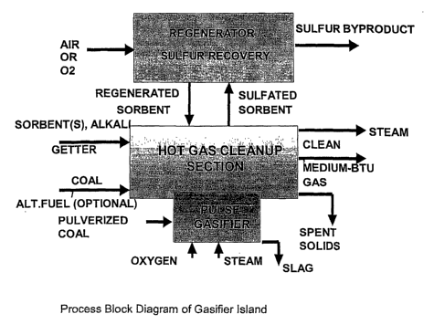
Fig. 1 is an exemplary block flow diagram of one embodiment of the pulse
gasification system of the present invention;
Fig. 2 shows an elevation view of one embodiment of the pulse gasifier of
the present invention;
Fig. 3 is a cut out view of one embodiment of the pulse gasifier of the
present invention;
Fig. 4 is a cross sectional view of one embodiment of a pulse combustion
device that may be used in the system and process of the present invention;
Fig. 5 is a graphical depiction of the relationship between % sulfur capture
and adiabatic gas temperature under reducing conditions in accordance with one
embodiment of the present invention;
Fig. 6 is a graphical depiction of the relationship between sulfur retention
(as CaS or CaS04) and temperature in accordance with one embodiment of the
present invention;
Fig. 7 is a schematic diagram of one embodiment of a pulsed gasifier
combined cycle for coal in accordance with the present invention; and
Fig. 8 is a graphical depiction of the relationship between net plant
efficiency and the fraction of coal feed to a pulsed gasifier in accordance
with one
embodiment of the present invention.
Repeat use of reference characters in the present specification and
drawings is intended to represent same or analogous features or elements of
the
invention.
6
CA 02486873 2004-11-22
WO 03/099965 PCT/US03/16428
Detailed Description of Representative Embodiments
It is to be understood by one of ordinary skill in the art that the present
discussion is a description of exemplary embodiments only, and is not intended
as
limiting the broader aspects of the present invention, which broader aspects
are
embodied in the exemplary construction.
The present invention is generally directed to an innovative pulse
gasification system that overcomes many of the limitations of prior pulse
gasification systems and may be configured to comply with stipulated new
emissions target of one-tenth of NSPS. For example, in one embodiment, the
system and process of the present~invention can be configured to emit less
than
about 0.12 Ib/MMBTU of sulfur dioxide, less than about 0.06 Ib/MMBTU of
nitrous
oxides (NOX), and/or less than about 0.003 Ib/MMBTU of particulates.
In one embodiment, the pulse gasifier system includes a pulse unit for first-
stage gasification, a U-tube arrangement for slag removal, and may also
include a
vertical entrained flow section for second-stage gasification and primary and
secondary cyclones for particulate capture. The feedstock can be coal, coke,
biomass, heavy liquid hydrocarbon, etc., and can be in the form of solids,
heavy
liquids, slurries, etc. Oxygen and steam may be used as gasification agents to
enhance product gas heating value, as well as to promote flame stability and
turndown. In the case of a combined cycle configuration, this also helps boost
the
gas turbine inlet temperature and plant efficiency. Air may be used as a
gasification agent, although it may, in some instances, lower the heating
value of
the gas produced due to the diluent nitrogen. Compressed air may be used to
pneumatically convey the solid fuels from the metering bin to the pulse
gasifier.
Superheated steam may also be used as transport/carrier fluid. Superheated
steam is the preferred carrier for dry solid feedstock in some embodiments.
The pulse gasifier incorporates one or two gasification stages to facilitate
good carbon conversion, high sound pressure level for acoustic agglomeration,
and good in-situ sulfur capture. In the two-stage case, the first stage can
operate
in the slagging mode and under sub-stoichiometric conditions. In the presence
of
oxygen and steam, feedstock devolatilizes and partially oxidizes to release
heat
7
CA 02486873 2004-11-22
WO 03/099965 PCT/US03/16428
for the steaml feedstock gasification reactions to proceed. The high operating
temperature (e.g., 2,500°F - 3,400°F) can ensure high carbon
version and aid ash
melting and slag flow.
In conventional slagging gasifiers, the slag region corresponds to an active
zone with gas-solids mixing, combustion, and slag tapping, all occurring above
the
hearth plate. The design and the ability to keep the slag tapping process
functioning are sometimes important. The art is to retain the solids within
the
gasifier and yet allow the liquid slag to drain through the tap hole at the
desired
rate. In the pulse gasifier of the present invention, the slag region can
correspond
to an active and a passive zone. In the active zone, partial oxidation, steam
gasification, and slag formation can take place, while the slag is tapped from
the
passive zone. Consequently, the slag removal processlhardware design is
comparatively simple, with essentially the only requirement that the slag tap
hole
not be allowed to freeze shut.
In the two-stage configuration, a U-tube coupling arrangement can be
provided between the first and second stages to ensure that molten slag can be
collected efficiently and withdrawn from a port at the base of the U-tube.
Slag is
anticipated to predominantly flow along the bottom side of the first half of
the U-
bend into the slag tap hole and then into a slag quench bath. In addition,
this
configuration forces the exit jets from the tailpipes to impinge on the
concave
sections and spin around. This enhances the mixing within the chamber, as well
as the residence time of the carbon to optimize the carbon conversion
efficiency.
The second stage may or may not be employed. This will depend on the
temperature of operation of the first stage as dictated by the reactivity of
the
feedstock and the slag temperature of the ash (e.g., biomass and lignite are
not
refractory and have lower ash slagging temperature). In other embodiments, the
feed stock chosen may not produce slag or the system may be configured in
order
to prevent the formation of slag.
In the case of a two-stage system, the second stage can include a vertical
refractory-lined section in which additional feedstock is injected to react
with the
hot gases from the first stage to enhance the product gas heating value and to
CA 02486873 2004-11-22
WO 03/099965 PCT/US03/16428
cool the product gas into the threshold for in-situ sulfur capture. An
additional port
can be provided directly below the riser in the second-stage to catch any
sorbent-
ash agglomerates that fall down. Oxygen and steam may be used to fluidize the
media in the agglomerate catch section. For example, oxygen can be employed
to enhance char conversion and steam can be used to regulate the temperature
in
the second-stage. In an alternative embodiment, only steam may be injected
into
the second stage in order to promote the endothermic reactions that occur
during
steam gasification.
The average gas temperature in the second stage can be from about
1000°F to about 2500°F. Inspection of the temperature dependence
of sulfur
capture at equilibrium under reducing conditions, such as shown in Figs. 5-6,
indicates that this gas temperature is in the appropriate temperature window
(e.g.,
from about 1,400°F to about 2,400°F) for sulfur capture
efficiencies greater than
90 percent with calcium-based sorbents. Sulfur capture efficiency in a dynamic
(non-equilibrium) situation depends on the temperature of the particle and not
that
of the gas.
With endothermic calcination, limestone or dolomite sorbent generally
requires time to reach the gas temperature. The strategy sometimes adopted in
the second stage is such that the sorbent will be injected near the base where
the
temperature is highest to assist calcination. If regenerable sorbents such as
cerium oxide are used, the sorbent can be injected further downstream of the U-
bend or in the middle area of the second stage. If desired, the residence time
of
the sorbent in the second stage can be controlled by optimizing the location
of the
sorbent injection port. Thus, in this embodiment, the sorbent particles flow
into the
middle section of the second stage (maintained at about 2,000°F) well
before
thermodynamics impose constraints on sulfur capture. Such a strategy can
ensure maximum sulfur capture for a specified sorbent particle residence time.
If
necessary, pulverized alkali gettering material, such as emathlite, hectorite
or
kaolinite, can also be injected into the second stage to aid alkali vapor
capture.
Agglomeration of ash in the second stage can have a significant advantage.
For example, in some instances, such agglomeration can facilitate the use of
one
9
CA 02486873 2004-11-22
WO 03/099965 PCT/US03/16428
or more conventional particulate capture devices, such as hot cyclones, to
bring
down the particulates in the gas stream to acceptable levels without recourse
to
the more expensive candle filtration or problematic slag screens. In such a
case,
the second stage effectively acts as a dynamic filter in which fly ash from
the coal
fines agglomerate with the larger sorbent particles due to collisions between
the
fine particles and the sorbent agglomeration foci.
Acoustic agglomeration is a pretreatment process that increases the
average size of entrained particles, making it possible to obtain high
collection
efficiency using hot cyclones. It is often desirable to use two cyclones,
wherein
the primary cyclone is a low velocity cyclone to capture agglomerates with
minimal
breakup and the secondary cyclone is a high velocity, high efficiency cyclone
to
capture the fines. The relatively clean product gas from the secondary cyclone
can be used for power generation or steam generation or as a process fuel or
for
hydrogen production or for direct reduction of iron or for liquid fuels
production and
other synthetic gas applications. The solids catch from the hot cyclones
contains
both spent sorbents as well as some unconverted carbon. The extent of the
unconverted carbon can be controlled and typically depends on the process
objectives and performance requirements.
In one embodiment, sorbent particles are injected into a gas stream
subjected to an intense acoustic field within the second stage. The acoustic
field
serves to improve sulfur capture efficiency by enhancing both gas film and
intra-
particle mass transfer rates. In addition, the sorbent particles act as
dynamic filter
foci, providing a high density of stagnant agglomerating centers for trapping
the
finer entrained (in the oscillating flow field) fly ash fractions. The fly ash
fractions
have particle sizes that are generally about 20 microns or less, and in some
embodiments, from about 1 to about 20 microns. Therefore, by introducing
sorbent particles, which are primarily concentrated in the size range from 20
to
150 microns, a bimodal distribution is created. The bimodal distribution
offers
several advantages. First, by increasing the density (in the gas) of large
stagnant
trap centers, an accelerated agglomeration rate can be achieved. Second,
agglomeration can be efficiently performed at a significantly lower acoustic
CA 02486873 2004-11-22
WO 03/099965 PCT/US03/16428
frequency range compared to unimodal distributions containing only finer fly
ash
fractions.
The effectiveness of particle agglomeration at low frequencies can be
important in some instances. The rate of agglomeration is strongly influenced
by
the acoustic intensity level. Because low frequencies are generally attenuated
less than high frequencies, 'lower frequency operation are often more
effective.
Furthermore, low frequencies do not affect the performance of turbine blades,
while frequencies in the kHz range may couple into the system's natural
frequencies and cause blade fatigue failure. Finally, the cut-off particle
diameter
for 50 percent entrainment increases with a decrease in frequency and
therefore
lower frequency operation results in the entrainment of a larger proportion of
a
given particle feed size distribution and places less constraint on the upper
limit for
particle growth.
It is believed that some chemical reactions in the high temperature (e.g.,
1800°F - 3400°F) first stage are as follows:
Combustion: C + O~ = COZ
Partial Oxidation: C +'/~ 02 = CO
Gasification with CO2: C + C02 = 2C0
Gasification with HZO: C + H2O = CO + H2
Oxidation of H2: H2 +'/z O2 = H2O
Oxidation of S: S + O~ _ SO2
Reduction of Sulfur: H~ + S = H2S
Ash Transformation: Ash = Halides, Sulfides, Oxides
The hot fuel gas exiting the first stage can react with the fuel injected into
the second-stage entrance (when desired) for a two-stage configuration. Here,
the
additional fuel devolitilizes and gasifies. Further downstream, the sorbent
injected
calcines, if applicable, and undergoes sulfidation. The temperature in the
second
stage decreases from the inlet (about 2,500°F) to the exit (about
1,700°F). It is
11
CA 02486873 2004-11-22
WO 03/099965 PCT/US03/16428
believed that some chemical reactions in this zone are as follows:
Combustion: C + O~ = COZ
Partial Oxidation: C +'/2 02 = CO
Gasification with C02: C + C02 = 2C0
Gasification with HBO: C + H20 = CO + H2
Gas Shift: CO + HBO = C02 + H2
Gasification: C + H20 = 1 /2C02 +'/z CH4
NH3 Formation: N2 + 3H2 = 2 NH3
Oxidation of H2: HZ +'/2 02 = HBO
Oxidation of S: S + OZ = S02
S Transformation: S + H2 = HZS
S+CO=COS
Ash Transformation: Ash = Halides, Sulfides, Oxides
Calcination: Ca C03 = Ca0 + C02
Sulfidation: Ca0 + SOZ + 3 CO = CaS + 3C0~
Ca0 + H2S = CaS + H20
Ca0 + COS = CaS + CO~
(OR)
2Ce02 + 3 SO~ + 10 HZ = Ce2S3 + 10 H20
2Ce0~ + 3 H2S + HZ = Ce~S3 +
4 H20
2Ce0a + 3 COS + HZ = Ce2S3 + H20 + 3
CO2
If the fuel contains more than a trace of (~10ppm) of halogens (CI, F, Br, I),
then the acid gases (HCI, HF, etc.) sometimes formed from the halogens and the
ash halides (NaCI, KCI, etc.) can be captured as well to generate a clean fuel
gas.
The temperature window for effective capture of these species, however, is
often
lower and can range from about 1,000°F to about 1,400 °F. Sodium-
based
absorbents (shortite, nahcolite, etc.) are preferred for acid gas (HCI, HF,
etc.)
12
CA 02486873 2004-11-22
WO 03/099965 PCT/US03/16428
uptake and alkali getters (kaolinite, emathlite, diatomaceous earth, bauxite,
etc.)
are preferred for alkali (NaCI, KCI, etc.) capture through a combination of
physical
adsorption and chemical reactions. The corresponding reactions are given
below:
Halogen Transformation: HZ + CIz = 2 HCI
H2+F2=2 HF
Acid Gas Removal: Na2 C03 (s) + 2HCI (g) = 2NaCl (s) + HBO (g) + C02 (g)
Na2 C03 (s) + 2HF (g) = 2NaF (s) + HBO (g) + C02 (g)
Alkali Removal: 2NaCl (v) + AI203 - 6 Si02 (s) + H20 (v) _
AI203 Na20-6Si02 (s) +2HCI (g)
wherein, the letters in parenthesis () denote the phase of the substance,
i.e., the letter "s" denotes solid; "g", gas; and "v", vapor.
As stated above, the fuel gas is generally cooled to a temperature of about
1,200°F to remove acid gas and alkali vapor. If halogens are present in
the feed,
the second-stage exit temperature can be lower (e.g., about 1,200°F)
than when
halogens are absent (e.g., from about 1,700°F to about 1,900°F).
This can be
accomplished using fuel gas cooling that may be carried out by external or
internal
means. A water jacket around part of the second-stage column upstream of the
exit could, for example, provide external cooling. Since the medium to be
cooled
is primarily a gas or a gas-solid mixture, the heat-transfer surface area
required for
fuel gas cooling is typically rather large, which may give rise to an even
taller
second stage. Also, the corrosive nature of the fuel gas may require careful
heat
exchanger material selection, which may add to the cost of the unit. Thus, in
some embodiments, water can be directly sprayed into the fuel gas through an
atomizer spray head to perform the cooling. Due to the sensible and latent
heat
contribution, the water mass addition is generally small relative to the fuel
gas
mass. For instance, the water injection rate typically does not exceed about
5% of
the fuel gas flow rate, on a mass basis. This is slightly lower the heating
value of
the fuel gas generated. Alternately, the fuel gas may be cooled downstream of
the
cyclones and passed through a bed of sorbent particles to remove acid gases, a
sulfur polisher to further reduce sulfur content and a hot gas barrier filter
to remove
13
CA 02486873 2004-11-22
WO 03/099965 PCT/US03/16428
any entrained particulate matter.
Typically, between 50 to 100% of the fuel undergoes the first-stage
gasification and the remainder (0 - 50%) may be injected at the entrance to
the
second-stage. The actual fuel split between the first-stage and the second-
stage
will depend upon the application, fuel properties and the unit size.
Stoichiometry
will also depend upon the application, fuel properties and the unit size. For
instance, the first-stage stoichiometry can span the range between 30 to 60
percent and the overall stoichiometry can be within the bounds of 25 and 50
percent.
Computer simulations indicate that the clean fuel gas generated in the
pulse gasifier should have a heating value on the order of 275 Btu/scf on a
wet
basis, if the fuel does not have halogens. If the fuel has halogens, the
heating
value will be lower and range between 250 and 275 Btu/scf depending on the
concentration of halogens in the fuel.
If desired, the pulse gasifier may be employed in combined cycle
configurations with varying combinations of fuel cell, gas turbine and steam
turbine
for power generation or in cogeneration configurations for combined heat and
power production, for hydrogen production, for liquid fuels production, for
direct
reduction of iron, or other synthetic gas applications. One embodiment for
power
generation is described below. Other embodiments can be formulated for
different
applications by integrating the pulse gasifier with components such as fuel
cell,
gas turbine, pressure swing absorbers for H2 production, liquefaction reactors
for
liquid fuels production, etc.
Referring to Fig. 1, a block diagram illustrating one embodiment of a
process according to the present invention is shown. It should be understood,
however, that Fig. 1 is only provided for exemplary purposes and is not
intended
as limiting the invention in any manner.
Referring now to Fig. 7, one embodiment of a more detailed system made
in accordance with the present invention is shown. In particular, Fig. 7
depicts one
embodiment of a pulsed gasification combined cycle made in accordance with the
present invention.
14
CA 02486873 2004-11-22
WO 03/099965 PCT/US03/16428
As shown, the pulsed gasification combined cycle ("PGCC") includes the
following:
~ Coal-Handling and Feeding System (CHFS);
~ Sorbent-Handling and Feeding System (SHFS);
~ Alkali and Acid Gas Getter Handling and Feeding System (AGHFS);
~ Pulse Gasifier, Hot Cyclones and Topping Burner;
~ Gas Turbine Generator Set;
~ Atmospheric Fluidi~ed Bed SulfaterlCombustor (AFBSC);
~ Heat-Recovery Steam Generator (HRSG);
~ Steam Turbine Generator Set and Steam Cycle Components;
~ Baghouse;
~ Ash, Spent Sorbent and Slag handling and storage system; and
~ Air Separation Plant.
The detailed description of the system and process illustrated in Fig. 7 will
now be described. It should'be understood that Fig. 7 is being provided for
exemplary purposes only and is not intended as limiting any of the features
and
aspects of the present invention. For example, none of the streams depicted in
Fig. 7 should be interpreted as being necessary or critical to the present
invention.
Further, many of the features and aspects illustrated and described in Fig. 7
may
be used in other alternative embodiments of the present invention.
In the embodiment shown in Fig. 7, the combined cycle has an open gas
cycle and a closed steam cycle. This embodiment generates a fuel gas of
heating
value comparable to that in oxygen-blown IGCC. This embodiment is flexible
enough for adaptation to both Greenfield and retrofit applications.
As shown in Fig. 7, the system includes a pulse gasifier generally 10,
embodiments of which are also shown in Figs. 2 and 3. The pulse gasifier 10
includes a pulse combustion device 12 contained within a fluid channel 14.
Referring to Fig. 4, one embodiment of the pulse combustion device 12 is
shown.
Pulse combustion device 12 includes a combustion chamber 18 in communication
with a resonance tube 20. Combustion chamber 18 can be connected to a single
resonance tube as shown or a plurality of parallel tubes having inlets in
separate
CA 02486873 2004-11-22
WO 03/099965 PCT/US03/16428
communication with the pulse combustion chamber. Fuel, an oxygen source,
and/or
steam are fed to the combustion chamber 18 via a fuel line 22 and an air
plenum 24.
Pulse combustion device 12 can burn either a gaseous, a liquid or a solid
fuel. For
most applications, a gaseous fuel, for instance, may be used to initiate
startup.
Once operating, a liquid or solid fuel may then be fed to the combustion
chamber.
In order to regulate the amount of fuel and gases fed to the combustion
chamber 18, the pulse combustion device 12 can include at least one valve 26.
The
valve 26 may be an aerodynamic valve, although a mechanical valve or the like
may
also be employed.
During operation of the pulse combustion device 12, an appropriate fuel,
oxygen source and steam mixture passes through the valve 26 into the
combustion
chamber 18 and is detonated. During startup, an auxiliary firing device such
as a
spark plug or pilot burner may be provided. Explosion of the fuel mixture
causes a
sudden increase in volume and evolution of combustion products which
pressurizes
the combustion chamber. As the hot gas expands, preferential flow in the
direction
of resonance tube 20 is achieved with significant momentum. A vacuum is then
created in the combustion chamber 18 due to the inertia of the gases within
the
resonance tube 20. Only a small fraction of exhaust gases are then permitted
to
return to the combustion chamber, with the balance of the gas exiting the
resonance
tube. Because the pressure of combustion chamber 18 is then below atmospheric
pressure, further fuel and gases are drawn into the combustion chamber 18 and
auto-ignition takes place. Again, valve 26 thereafter constrains reverse flow,
and the
cycle begins anew. Once the first cycle is initiated, operation is thereafter
self
sustaining.
Pulse combustion device 12 produces a pulsating flow of combustion
products and an acoustic pressure wave. In one embodiment, the pulse
combustion
device produces pressure oscillations or fluctuations in the range of from
about 1 psi
to about 40 psi and particularly from about 1 psi to about 25 psi peak to
peak.
These fluctuations are substantially sinusoidal. The pressure fluctuation
levels are
on the order of a sound pressure range or intensity of from about 150 dB to
about
194 dB, or greater. The acoustic pressure wave can be at a frequency of from
16
CA 02486873 2004-11-22
WO 03/099965 PCT/US03/16428
about 20 Hz to about 1500 Hz. For most applications, however, lower
frequencies
are preferred. For instance, the frequency can be from about 25 Hz to about
250
Hz.
Although any suitable carbonaceous fuel may be combusted in the pulse
combustion device 12, in the embodiment illustrated in Fig. 7, coal is used as
the
fuel source. As shown, the system includes a coal handling and feeding system
28.
The coal is pulverized, combined with a carrier gas and fed to the combustion
device 12. The carrier gas may be compressed air as shown in Fig. 7. In this
particular embodiment, the compressed air is obtained from a compressor 30
that is
shown in association with a gas turbine generally 32.
In addition to coal, an oxygen source and/or steam are also fed to the pulse
combustion device 12. In this embodiment, for instance, substantially pure
oxygen
is combined with steam and fed to the pulse combustion device 12. The oxygen
is
obtained from an air separator 34 that receives compressed air from the
compressor
30.
For most applications, the pulse combustion device.12 is operated at sub-
stoichiometric conditions. In particular, oxygen is fed to the pulse
combustion device
in amounts insufficient to completely combust the fuel source. For example, in
one
embodiment, oxygen can be fed to the combustion device in an amount of from
about 30% to about 60% of stoichiometric levels on a mole basis.
As described above, oxygen may be fed to the pulse combustion device 12 in
conjunction with steam. Steam can be added in amounts sufficient to moderate
the
temperature of the pulsating combustion products and to promote steam
reforming
within the fluid channel 14. For example, when steam is present, some of the
fuel is
reformed undergoing endothermic reactions. The endothermic reactions take heat
away from the system and thereby moderate the temperature of the resulting
pulsating combustion stream. In general, steam may be present in amounts
sufficient to maintain the temperature of the combustion products at less than
about
4000°F., such as less than about 3400°F. For example, in one
embodiment, the
temperature can be maintained between about 1800°F. to about
3400°F., such as
from about 2500°F, to about 3400°F.
17
CA 02486873 2004-11-22
WO 03/099965 PCT/US03/16428
As shown, the fluid channel 14 has a U-shaped section. In some
embodiments, the fluid channel 14 can be maintained as a single stage system.
In
other embodiments, however, the fluid channel may be divided into a first
stage 36
containing the pulse combustion device 12 and a second stage 38 downstream. In
general, when slag is formed during the process, a two-stage system may be
desired. Slag may form, for instance, when using refractory feed stocks, such
as
petroleum coke or raw coal as shown in Fig. 7. When using coal as the feed
stock,
for instance, slag may form when temperatures rise above about 2000°F.
Thus, in one embodiment of the present invention, multiple processes may
occur within the first stage 36 of the fluid channel 14. For instance, not
only is a
pulsating combustion stream and an acoustic pressure wave formed, but partial
oxidation of the fuel source occurs in the first stage, steam gasification of
the fuel
source, and slag formation. Of particular advantage, since the fluid channel
14 has
a U-shaped section, slag, once formed, is directed into a port and collected
by a slag
handling system 40. The U-shaped section also enhances mixing of the pulsating
combustion stream that exits from the pulse combustion device 12.
In the second stage 38 of the fluid channel 14, the temperature of the
pulsating combustion stream is generally lowered and various additives mayrbe
added to the stream. For most applications, reducing conditions are maintained
within the second stage 38 in order to promote steam reforming and associated
endothermic reactions.
In one optional embodiment, for instance, a portion of the pulverized coal
from the coal handling and feeding system 28 may be injected into the second
stage
38. Once injected into the second stage of the fluid channel, the fuel
undergoes
steam gasification. If necessary, further amounts of steam as shown in Fig. 7
may
also be injected into the second stage 38 of the fluid channel 14. Minor
amounts of
oxygen may be present in the second stage. For most applications, however,
oxidation should not be the primary driving force.
As shown in Fig. 7, a sulfur capturing agent is injected into the second stage
38 from a sorbent handling and feeding system 42. The sulfur capturing agent
serves two purposes. First, the sulfur capturing agent removes sulfur from the
18
CA 02486873 2004-11-22
WO 03/099965 PCT/US03/16428
pulsating combustion stream. Second, the sulfur capturing agent also
facilitates
agglomeration of flyash or other small particulates contained within the
pulsating
combustion stream.
The sulfur capturing agent, in one embodiment, may be limestone, dolomite,
or mixtures thereof. These sulfur capturing agents capture sulfur through
endothermic reactions. Thus, limestone and dolomite may need to be heated
prior
to the desirable reactions occurring. Consequently, these agents may be
injected
more towards the U-shaped section of the fluid channel.
In an alternative embodiment, however, cerium oxide may be used as a
sulfur capturing agent. Cerium oxide may generally be added anywhere along the
length of the second stage 38.
As described above, due to the presence of the acoustic pressure wave, the
sulfur capturing agent agglomerates with particulates contained within the
pulsating
combustion stream. Some of the agglomerates will continue to travel with the
pulsating combustion stream. Other portions of the agglomerates, however, may
fall
within the second stage 38. Not shown, a port may be provided directly below
the
riser in the second stage that serves to catch any such agglomerates.
When halogens are present in the pulsating combustion stream, in some
embodiments, it may be necessary to also inject an alkali gettering agent into
the
second stage 38 of the fluid channel 14. For instance, an alkali gettering
agent may
be injected into the second stage via an alkali and acid gas getter handling
and
feeding system 44.
When removing halogens, lower temperatures may be required. In this
regard, the system can also include a water port 46 configured to inject or
spray
water into the second stage 38 and cool the pulsating combustion stream.
The inlet temperature of the second stage 38 may vary from about
1800°F. to
about 3000°F. Likewise, the exit temperature of the second stage may
also vary. In
some embodiments, for instance, the exit temperature may be less than about
1900°F., such as less than about 1700°F. When halogens are
present, however,
the exit temperature may be less than about 1400°F., such as from about
1000°F, to
about 1200°F.
19
CA 02486873 2004-11-22
WO 03/099965 PCT/US03/16428
The pressure within the fluid channel 14 may vary depending upon the
particular application. For example, the pressure within the fluid channel can
be
from about atmospheric pressure to about 20 times atmospheric pressure. In one
embodiment, for instance, the pressure can be from about 10 times atmospheric
pressure to about 20 times atmospheric pressure.
In general, the pulse gasifier 10 may convert between about 90% and about
96% of the carbon contained in the fuel source. The gas that is formed by the
pulse
gasifier may contain relatively large amounts of hydrogen in combination with
other
gases. The other gases may include, for instance, carbon dioxide, carbon
monoxide, and lighter hydrocarbons.
The clean gas generated in the pulse gasifier has a heating value on the
order of 250 Btu/scf on a wet basis. This value is comparable to that reported
for
gases generated in oxygen-blown IGCC, but exceeds the heating value of low-Btu
gases generated in air-blown IGCC and second-generation PFBC.
As shown in Fig. 7, from the pulse gasifier 10, the product gas stream is then
fed to a tandem pair of cyclones 48 and 50. Of particular advantage, due to
the
effective agglomeration that occurs within the pulse gasifier, low energy
cyclones 48
and 50 may be used in order to remove the agglomerated particulates. In one
embodiment, cyclone 48 may be a low velocity cyclone for removing the larger
particulates. For example, gas velocities in the cyclone 48 may be from about
30
ft/sec to about 75 ft/sec.
The second cyclone 50, on the other hand, may be a high velocity, high
efficiency cyclone well configured to removing smaller particulates such as
fines.
Gas velocity in the cyclone 50 may be, for instance, from about 50 ft/sec to
about
200 ft /sec.
Once the particulate material is removed from the product gas stream using
the cyclones 48 and 50, the product gas may be used in an almost limitless
variety
of processes. In one embodiment, for instance, as shown in Fig. 7, the product
gas
stream may be used for the production of electricity. As shown in Fig. 7, for
instance, the product gas stream from the cyclone 50 is fed to a topping
burner 52.
The topping burner 52 includes a combustor that combusts the product stream
and
CA 02486873 2004-11-22
WO 03/099965 PCT/US03/16428
increases the gas temperature. For example, in one embodiment, the gas
temperature can be increased to from about 2300°F. to about
2600°F. In order to
combust the product gas stream, the topping burner may combine the product gas
stream with an oxygen source, such as air if desired.
The combustor contained within the topping burner can be any suitable
combustion device. In one embodiment, for instance, the combustor contained
within the topping burner can be a pulse combustor or a low BTU fuel gas
combustor. Examples of low BTU fuel gas combustors have been developed by GE
Environmental Services, Inc. and Siemens Westinghouse Electric Corporation.
As shown in Fig. 7, the topping burner produces a flue gas stream that is
then fed to the gas turbine 32. In particular, the flue gas stream is used to
rotate a
turbine 54 and produce electricity. As also shown in Fig. 7, in one
embodiment, the
flue gas stream exiting the turbine can be fed to a heat recovery steam
generator 56
for generating steam from a feed water. The flue gas then exits the heat
recovery
steam generator 56 and is released to the atmosphere through a stack 58.
In an alternative embodiment, instead of sending the product gas stream to a
gas turbine as shown in Fig. 7, the product gas stream can be fed to a fuel
cell. In
this embodiment, the topping burner 52 is not required. Instead, various gas
conditioning and polishing systems may be incorporated into the system in
order to
purify the gas prior to being fed to the fuel cell. In particular, the gas
conditioning
and polishing systems may serve to concentrate the amount of hydrogen
contained
within the product gas for use in the fuel cell.
As described above, during the process of the present invention, sulfur is
captured from the pulsating combustion stream. The sulfur is contained in the
sulfur
capturing agents. The sulfur capturing agents are collected within the fluid
channel
14 and within the cyclones 48 and 50. In some embodiments, it may be desirable
to
further treat the agglomerated particles. In this regard, as shown in Fig. 7,
the
system further includes an atmospheric fluidized bed sulfater 60. In one
embodiment, for instance, the sulfur capturing agent may be lime or limestone.
Under a reducing environment as may occur in the fluid channel 14, sulfur
captured
by the sorbent is primarily through the formation of sulfide. Unfortunately,
calcium
21
CA 02486873 2004-11-22
WO 03/099965 PCT/US03/16428
sulfide reacts with water to release hydrogen sulfide. Consequently, safe
disposal of
spent sorbent requires conversion to the more stable sulfated form. In the
process
of the present invention, this conversion can easily take place within the
sulfater 60.
Specifically, the solids collected from the pulse gasifier 10 and from the
cyclones 48 and 50 as shown in Fig. 7 are fed through a pressure letdown 62
and
into the sulfater 60. The solids caught from the cyclones contain both spent
sorbents and unconverted carbon. The unconverted carbon is, in fact, a desired
feature because it may be used to generate energy to maintain the sulfater at
the
required temperature for sulfide conversion.
Sulfur capture by lime/limestone is a complex process involving the following
reactions:
Ca0 + S02 +'/2 02 ~ CaS04 (1 )
Ca0 + SOz + 3 CO ~ CaS + 3 C02 (2)
Depending on the temperature and the gas conditions, the following reactions
may also occur:
CaS04 + CO ~ Ca0 + S02 + C02 (3)
CaS04 + 4 CO ~ CaS + 4 C02 (4)
CaS + 1 ~/Z 02 ~ Ca0 + S02 (5)
CaS + 2 02 -~ CaS04 (6)
Under the operating conditions of interest in the second-stage, reaction (2)
is
expected to occur. In the AFBSC 60, however, reactions (3-6) may occur.
Reaction
(6) is desired. However, reaction (3) and (5) are sometimes undesirable as
they
result in the release of captured sulfur. Consideration of the Ca-O~ S
equilibrium
diagram indicates that reaction (5) is most likely to occur under reducing
conditions
and at higher temperatures.
Thus, the sulfater is typically operated at temperatures lower than about
2,200°F and under oxidizing conditions to form CaS04 and maintain the
stability
thereof. The sulfater, in keeping with these requirements, can be designed as
a
fluidized bed operating at a temperature of about 1,550°F. Air
corresponding to
super-stoichiometric operation is used to fluidize the bed, which can ensure
that
excess oxygen is available for the oxidation reaction and oxidizing conditions
are
22
CA 02486873 2004-11-22
WO 03/099965 PCT/US03/16428
maintained within the bed. Unconverted carbon from the second-stage is burned
in
the sulfater 60 to maintain the bed temperature at the desired level.
Inspection of
the phase equilibrium data for Ca-OZ S system in the presence of carbon
combustion products indicates that presence of CO will adversely affect
sulfate
formation. Excess oxygen feed in the sulfater will ensure dominance of CO2.
Additional fresh sorbent may also be supplied to the bed to ensure that sulfur
oxides, if formed, can be captured within the bed.
As shown in Fig. 7, in one embodiment, raw coal may also be fed to the
sulfater if carbon levels are too low. For most systems, however, the addition
of a
further fuel source to the sulfater 60 may be unnecessary.
When the sulfater 60 is incorporated into the system of the present invention,
various energy integration steps may occur in order to further increase the
efficiency
of the overall process. For example, as shown in Fig. 7, in one embodiment,
compressed air from the compressor 30 may be fed through the fluidized bed of
the
sulfater 60 and preheated. The preheated compressed air may then be fed to the
topping burner 52 for combustion with the product gas stream. This is done to
increase the heat input to the gas cycle. In addition, the fluidized bed may
also
incorporate tube banks designed to generate steam. Further, the resulting flue
gas
exiting the fluidized bed of the sulfater 60 may be fed to a heat recovery
steam
generator 64 for also creating steam. The steam from the fluidized bed, the
steam
from the heat recovery steam generator 64 and the steam from the heat recovery
steam generator 56 may all then be fed to a steam turbine 66 to produce
further
amounts of electricity. Alternatively, the steam that is formed may be fed to
the
pulse gasifier 10 as desired.
As shown, once the flue gas stream produced by the sulfater 60 exits the
heat recovery steam generator 64, the gas is fed to a baghouse 68 and
filtered. Any
particulates captured by the baghouse are sent to ash storage 70. The filtered
gas,
on the other hand, is fed to the stack 58 and released to the atmosphere.
Instead of using limestone as the sulfur capturing agent, as described above,
in an alternative embodiment, cerium oxide may be used to capture sulfur. If a
sorbent such as cerium oxide is used to capture sulfur, the spent sorbent may
be
23
CA 02486873 2004-11-22
WO 03/099965 PCT/US03/16428
regenerated in an air or oxygen-rich environment. The reaction will correspond
to:
Ce2S3 + 5 02 = 2Ce02 + 3 SOZ
The above reaction can occur, for instance, in a fluidized bed much like the
sulfater 60 described in Fig. 7.
The S02generated may be reduced using a direct sulfur reduction process or
a Claus process to produce elemental sulfur or produce sulfuric acid or
ammonium
sulfate.
First-order estimates of the cycle efficiency for the combined cycle, such as
shown in Figure 7, were made for difFerent fuel splits between the Pulse
Gasifier and
AFBSC. Figure 8 shows the net plant efficiency (HHV basis) as a function of
the
fraction of the coal feed to the Pulse Gasifier. The value of 1 for this
fraction
corresponds to all the coal being fed into the Pulsed Gasifier and a value of
zero
corresponds to all the coal being fed into the AFBSC. Greenfield application
would
entail a coal feed fraction of near unity while retrofit application would
correspond to
low values (typically between 0.1 and 0.5) of this fraction. The net plant
efficiency
curves are shown for two cases: (1 ) 2,100°F gas turbine inlet
temperature and
1,450 psia/1,000°F/1,000°F steam cycle, and 2) 2,300°F
gas turbine inlet
temperature and 2,400 psia/1,000°F/1,000°F steam cycle. Case 1
is typical of
retrofit application and Case 2 is more suited to Greenfield application. The
net
plant efficiency increases with the fractional coal feed to the Pulse Gasifier
as
expected due to an increase in the higher temperature, more efficient gas
cycle
power generation. The net plant efficiency approaches 45 percent under the
advanced cycle conditions relevant to Greenfield applications. Further
improvements in efficiency are anticipated with steam-cooled gas turbine
blades by
substituting steam generated in the Pulse Gasifier for the compressed air. For
a
typical retrofit application, the net plant efficiency is projected between 33
and
37 percent. Of course, in all the cases, other benefits are also derived from
the
ability to meet 1 /10th NSPS emissions targets, a simpler combustor island
configuration without barrier filters and without the need for exotic
sorbents.
The advantages of the pulsed gas combined cycle ("PGCC") in comparison
with competing advanced power generation technologies are listed below in
Table 1
24
CA 02486873 2004-11-22
WO 03/099965 PCT/US03/16428
based on a preliminary evaluation. The PGCC offers comparable performance with
fewer components and shows potential for significant capital cost savings.
TABLE 1:
GENERATION IGCC SECOND
O Air PFBC Transport PGCC
BARRIER FILTER Yes Yes Yes Yes No
SYNGAS COOLER Yes Yes No Yes No
AIR SEPARATION Yes No No No Yes
UNIT
EX-SITU GAS CLEANUPYes Yes No Yes No
SULFUR RECOVERY Yes No No No No
LIQUID EFFLUENT Yes No No No No
TREATMENT
EFFICIENCY, % 37-42 40-44 44-46 '" 45 ~'
45
(HHV basis)
SONIC-ENHANCED FUR
SUL
CAPTURE No No No No Yes
CAPITAL COST SAVINGFOR
PGCC, $/kW 200-300100-200 50-150 50-100 -
Further, the PGCC system can offer some or all of the following benefits:
~ Eliminates one or more stages of barrier filtration for hot gas particulate
cleanup due to sonic-enhanced ash agglomeration. This enhances reliability,
plant availability, reduces capital and operating and maintenance costs and
requires less real estate.
~ Efficient in-situ sulfur capture in the sonic-enhanced mode together with
sorbent regeneration and sulfur recovery improves performance, reduces
waste, increase revenues and enhances economics.
~ Hot gas cleanup boosts process efficiency and lowers net heat rate.
~ Alternate fuels and/or biomass can be co-fired in the system.
CA 02486873 2004-11-22
WO 03/099965 PCT/US03/16428
~ Capital cost saving of between $200 and $300 per kW in comparison to current
IGCC systems.
~ Provides modularity and is amenable to shop fabrication.
~ The system can be offered in small sizes (25 MWe equivalent or larger) and
for
niche applications involving feedstocks such as petroleum coke, bitumen, etc.
~ Suitable for re-powering as well as Greenfield applications.
~ Staged gasification mode of operation facilitates NOx emissions control and
the
flexibility to progressively increase the turbine inlet temperature
(ultimately to
2,600°F) with advances in gas turbines.
~ The combustor island can be 100 percent coal-fired and auxiliary fuel such
as
natural gas or fuel oil need be used only for start-up.
~ The pulse gasifier system can be retrofitted to an AFBC as an add-on or
topper
to make up a combined-cycle application.
~ Shows promise for achieving higher cycle efficiency (~ 45%), lower emissions
(~ 1/10th NSPS), and lower cost of electricity.
~ No liquid effluent from the plant.
~ Provides modularity and is amenable to shop fabrication.
~ Permits staged or phased construction.
~ No exotic or unproven materials of construction.
~ The system can be configured for combined heat and power (CHP) application,
for hydrogen production, for direct reduction of iron, or for the production
of
liquid fuels.
These and other modifications and variations of the present invention may
be practiced by those of ordinary skill in the art, without departing from the
spirit
and scope of the present invention. In addition, it should be understood that
aspects of the various embodiments may be interchanged both in whole or in
part.
Furthermore, those of ordinary skill in the art will appreciate that the
foregoing
description is by way of example only, and is not intended to limit the
invention so
further described in such appended claims.
26