Note: Descriptions are shown in the official language in which they were submitted.
CA 02487032 2004-11-23
WO 2004/027907 PCT/CA2003/001449
-1-
Title: SYSTEM AND METHOD FOR PROCESS GAS STREAM DELIVERY
AND REGULATION USING DOWN SPOOL CONTROL
Field of the Invention
[0001] The present invention relates to a system and method for
delivering and regulating process gas streams to fuel cell stacks.
Backctround of the Invention
[0002] A fuel cell is an electrochemical device that produces an
electromotive force by bringing the fuel (typically hydrogen) and an oxidant
(typically air) into contact with two suitable electrodes and an electrolyte.
A
fuel, such as hydrogen gas, for example, is introduced at a first electrode
where it reacts electrochemically in the presence of the electrolyte to
produce
electrons and canons in the first electrode. The electrons are circulated from
the first electrode to a second electrode through an electrical circuit
connected
between the electrodes. Cations pass through the electrolyte to the second
electrode. Simultaneously, an oxidant, such as oxygen or air is introduced to
the second electrode where the oxidant reacts electrochemically in presence
of the electrolyte and catalyst, producing anions and consuming the electrons
circulated through the electrical circuit; the cations are consumed at the
second electrode. The anions formed at the second electrode or cathode
react with the cations to form a reaction product. The first electrode or
anode
may alternatively be referred to as a fuel or oxidizing electrode, and the
second electrode may alternatively be referred to as an oxidant or reducing
electrode. The half-cell reactions at the two electrodes are, respectively, as
follows:
H2 ~ 2H++2e-
11202 + 2H + +2e- -~ H20
[0003] The external electrical circuit withdraws electrical current and
thus receives electrical power from the cell. The overall fuel cell reaction
produces electrical energy as shown by the sum of the separate half-cell
reactions written above. Water and heat are typical by-products of the
reaction.
CA 02487032 2004-11-23
WO 2004/027907 PCT/CA2003/001449
-2-
[0004 In practice, fuel cells are not operated as single units. Rather,
fuel cells are connected in series, stacked one on top of the other, or placed
side by side. A series of fuel cells, referred to as fuel cell stack, is
normally
enclosed in a housing. The fuel and oxidant are directed through manifolds to
the electrodes, while cooling is provided either by the reactants or by a
cooling medium. Also within the stack are current collectors, cell-to-cell
seals
and insulation, with required piping and instrumentation provided externally
of
the fuel cell stack. The stack, housing, and associated hardware make up the
fuel cell module.
[0005 The optimal operating level of components of the fuel cell
system will depend upon the particular system operating level of the entire
fuel cell system. Thus, for example, the optimal operating level of a blower
for
providing a process fluid to the fuel cell system will depend upon the
particular
system operating level of the fuel cell system. As the operating level of the
fuel cell system increases, the optimal operating level of the blower will
also
increase. Analogously, as the operating level of the fuel cell decreases, the
optimal operating level of the blower will decrease. In prior art systems,
feedback from process parameters, such as cathode airflow, various
temperatures and fuel cell voltages, are monitored and are used to either
increase or decrease the operating level of individual components of the fuel
cell system based upon the needs of the fuel cell system.
Summary of the Invention
(0006] In accordance with an aspect of the present invention, there is
provided a method of operating a fuel cell system. The method comprises (a)
operating a component of the fuel cell system at a component operating rate;
(b) driving a load using the fuel cell; (c) measuring an operating rate of the
fuel cell; (d) normally adjusting the component operating rate in dependence
upon the operating rate of the fuel cell; and, (e) in response to selected
changes in the operating rate of the fuel cell, indicative of corresponding
changes in the demand from the load, delaying adjustment of the component
operating rate.
CA 02487032 2004-11-23
WO 2004/027907 PCT/CA2003/001449
-3-
[0007] In accordance with a second aspect of the present invention,
there is provided a fuel cell system comprising (a) a fuel cell for driving a
load;
(b) at least one measuring device for monitoring an operating rate of the fuel
cell; (c) a controller for controlling an operation rate of a component of the
fuel
cell system based on the operating rate of the fuel ceN; and, (d) means for
detecting selected changes in the operating rate of the fuel cell, indicative
of
corresponding changes in the demand from the load, and in response thereto,
delaying adjustment of the operation rate of the component.
Brief Description of the Drawings
[0008] For a better understanding of the present invention and to show
more clearly how it may be carried into effect, reference will now be made, by
way of example, to the accompanying drawings which show an embodiment
of the present invention and in which: ,
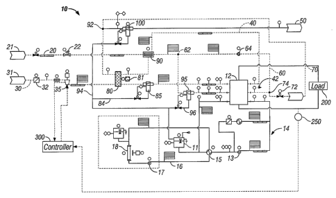
[0009] Figure 1 is a schematic flow diagram of a first embodiment of a
fuel cell gas and water management system in accordance with an aspect of
the present invention; and,
[0010) Figure 2 is a block diagram of a controller for use in connection
with the fuel cell gas and water management system of Figure 1 in
accordance with an embodiment of the invention.
Detailed Description of the Invention
[0011] For.delivering and regulating process fluids, for example air and
hydrogen gas streams, to a fuel cell stack, it is important to provide the
process fluids in a required amount at a precise time. The following
description will use as an example the delivery and regulation of air to a
cathode portion of a fuel cell stack 12. The same genera! principles can also
be applied to other fluid deliveries, for example the hydrogen gas stream to
the fuel cell stack.
[0012] Referring to Figure 1, this shows a schematic flow diagram of a
fuel cell gas management system 10 in accordance with an aspect of the
CA 02487032 2004-11-23
WO 2004/027907 PCT/CA2003/001449
-4-
present invention. The fuel cell gas management system comprises a fuel
supply line 20, an oxidant supply line 30, a cathode exhaust recirculation
line
40 and an anode exhaust recirculation line 60, all connected to the fuel cell
12. It is to be understood that the fuel cell may comprise a plurality of fuel
cells (a fuel cell stack) or just a single fuel cell. For simplicity, the fuel
cell 12
described herein operates on hydrogen as fuel and air as oxidant and can be
a Proton Exchange Membrane (PEM) fuel cell. However, the present
invention is not limited to this type of fuel cells and is applicable to other
types
of fuel cells that rely on other fuels and oxidants.
[0013) The fuel supply line 20 is connected to a fuel source 21 for
supplying hydrogen to the anode of the fuel cell 12. A hydrogen humidifier 90
is disposed in the fuel supply line 20 upstream from the fuel cell 12 and an
anode water separator 95 is disposed between the hydrogen humidifier 90
and the fuel cell 12. The oxidant supply line 30 is connected to an oxidant
source 31, e.g. ambient air, for supplying air to the cathode of the fuel cell
12.
An enthalpy wheel 80 is disposed in the oxidant supply line 30 upstream of
the fuel cell 12 and also in the cathode recirculation line 40. A cathode
water
separator 85 is disposed between the enthalpy wheel 80 and the fuel cell 12.
The enthalpy wheel 80 comprises porous materials with a desiccant. In known
manner, a motor 81 drives either the porous materials or a gas diverting
element to rotate around the axis of the enthalpy wheel so that gases from the
oxidant supply line 30 and the oxidant recirculation line 40 alternately pass
through the porous materials of the enthalpy wheel. Dry ambient air enters the
oxidant supply line 30 and first passes through an air filter 32 fihat filters
out
the impurity particles. A blower 35 is disposed upstream of the enthalpy wheel
80, to draw air from the air filter 32 and to pass the air through a first
region of
the enthalpy wheel 80. The enthalpy wheel 80 may be any commercially
available enthalpy wheel suitable for fuel cell system, such as the one
described in the applicant's co-pending U.S Patent Application No.
091941,934.
CA 02487032 2004-11-23
WO 2004/027907 PCT/CA2003/001449
-5-
[0014] A fuel cell cathode exhaust stream contains.excess air, product
water and water transported from the anode side, the air being nitrogen rich
due to consumption of at least part of the oxygen in the fuel cell 12. The
cathode exhaust stream is recirculated through the cathode exhaust
recirculation line 40 connected to the cathode outlet of the fuel cell 12. The
humid cathode exhaust stream first passes through the hydrogen humidifier
90 in which the heat and humidity is transferred to incoming dry hydrogen in
the fuel supply line 20. The humidifier 90 can be any suitable humidifier,
such
as that commercially available from Perma Pure Inc, Toms River, NJ. It may
also be a membrane humidifier and other types of humidifier with either high
or low saturation efficiency. In view of the gases in the anode and cathode
streams, an enthalpy wheel or other device permitting significant heat and
humidity interchange between the two streams cannot be used.
[0015] From the hydrogen humidifier 90, the fuel cell cathode exhaust
stream continues to flow along the recirculation line 40 and passes through a
second region of the enthalpy wheel 80, as mentioned above. As the humid
cathode exhaust passes through the second region of the enthalpy wheel 80,
the heat and moisture is retained in the porous paper or fiber material of the
enthalpy wheel 80 and transferred to the incoming dry air stream passing
through the first region of the enthalpy wheel 80 in the oxidant supply line
30,
as the porous materials or the gas diverting element of the enthalpy wheel 80
rotate around its axis. Then the cathode exhaust stream continues to flow
along the recirculation line 40 to an exhaust oxidant wafer separator 100 in
which the excess water, again in liquid form, that has not been transferred to
the incoming hydrogen and air streams is separated from the exhaust stream.
Then the exhaust stream is discharged to the environment along a discharge
line 50.
[0016] A drain line 42 may optionally be provided in the recirculation
line 40 adjacent the cathode outlet of the fuel cell to drain out any liquid
water
remaining or condensed out. The drain line 42 may be suitably sized so that
gas bubbles in the drain line actually retain the water in the drain line and
CA 02487032 2004-11-23
WO 2004/027907 PCT/CA2003/001449
-6-
automatically drain water on a substantially regular basis, thereby avoiding
the need of a drain valve that is commonly used in the field to drain water
out
of gas stream. Such a drain line can be used anywhere in the system where
liquid water needs to be drained out from gas streams. Pressure typically
increases with gas flow rate and water regularly produced or condensed, and
a small flow rate of gas is not detrimental such as cathode exhaust water
knockout separator and drain line 42.
[0017 The humidified hydrogen from the hydrogen humidifier 90 flows
along the fuel supply line 20 to the anode water separator 95 in which excess
water is separated before the hydrogen enters the fuel cell 12. Likewise, the
humidified air from the enthalpy wheel 80 flows along the oxidant supply line
30 to the cathode water separator in which excess liquid water is separated
before the air enters the fuel cell 12.
[0018] Fuel cell anode exhaust comprising excess hydrogen and water
is recirculated by a pump 64 along an anode recirculation line 60 connected to
the anode outlet of the fuel cell 12. The anode recirculation line 60 connects
to the fuel supply line 20 at a joint 62 upstream from the anode wafer
separator 95. The recirculation of the excess hydrogen together with water
vapor not only permits utilization of hydrogen to the greatest possible extent
and prevents liquid water from blocking hydrogen reactant delivery to the
reactant sites, but also achieves self-humidification of the fuel stream since
the water vapor from the recirculated hydrogen humidifies the incoming
hydrogen from the hydrogen humidifier 90. This is highly desirable since this
arrangement offers more flexibility in the choice of hydrogen humidifier 90 as
the humidifier 90 does not then need to be a highly efficient one in the
present
system. By appropriately selecting the hydrogen recirculation flow rate, the
required efficiency of the hydrogen humidifier 90 can be minimized. For
example, supposing the fuel cell 12 needs 1 unit of hydrogen, hydrogen can
be supplied from the hydrogen source in the amount of 3 units with 2 units of
excess hydrogen recirculated together with water vapor. The speed of pump
64 may be varied to adjust the portion of recirculated hydrogen in the mixture
CA 02487032 2004-11-23
WO 2004/027907 PCT/CA2003/001449
_7_
of hydrogen downstream from joint 62. The selection of stoichiometry and
pump 64 speed may eventually lead to the omission of the hydrogen
humidifier 90.
[0019] In practice, since air is used as oxidant, it has been found that
nitrogen crossover from the cathode side of the fuel cell to the anode side
can
occur, e.g. through the membrane of a PEM fuel cell. Therefore, the anode
exhaust actually may contain some nitrogen and possibly other impurities.
Recirculation of anode exhaust may result in the build-up of nitrogen and
poison the full cell. Preferably, a hydrogen purge line 70 branches out from
the fuel recirculation line 60 from a joint or connection 74 adjacent the fuel
cell
cathode outlet, A purge control device 72 is disposed in the hydrogen purge
line 70 to purge a portion of the anode exhaust out of the recirculation line
60.
The frequency and flow rate of the purge operation is dependent on the power
at which the fuel cell 12 is running. When the fuel cell 12 is running at high
power, it is desirable to purge a higher portion of anode exhaust. The purge
control device 72 may be a solenoid valve or other suitable device.
(0020] The hydrogen purge line 70 runs from the position 74 to a joint
or connection 92 at which it joins the cathode exhaust recirculation line 40.
Then' the mixture of purged hydrogen and the cathode exhaust from the
enthalpy wheel 80 passes through the exhaust water separator 100. Water is
condensed in the water separator 100 and the remaining gas mixture is
discharged to the environment along the discharge line 50. Alternatively,
either the cathode exhaust recirculation line 40 or the purge line 70 can be
connected directly into the water separator 700.
[0021] Preferably, water separated by the anode water separator 95,
the cathode water separator 85, and the exhaust water separator 100 is not
discharged, but rather the water is recovered, from these separators
respectively, along a line 96, a line 84 and a line 94 to a product water tank
(not shown).
[0022] As is known to those skilled in the art, a coolant loop 14 runs
through the fuel cell 12. A pump 13 is disposed in the cooling loop 14 for
CA 02487032 2004-11-23
WO 2004/027907 PCT/CA2003/001449
_$_
circulating the coolant. The coolant may be any coolant commonly used in the
field, such as any non-conductive water, glycol, etc. An expansion tank 11 can
be provided in known manner. A heat exchanger 15 is provided in the cooling
loop 14 for cooling the coolant flowing through the fuel cell 12 to maintain
the
coolant within an appropriate temperature range. Fig. 1 shows one variant, in
which a secondary loop 16 includes a pump 17, to circulate a secondary
coolant. A heat exchanger 18, e.g. a radiator, is provided to maintain the
temperature of the coolant in the secondary loop and again, where required,
an expansion tank 19 is provided. The coolant in the cooling loop 16 may be
any type of coolant as the coolants in cooling loop 14 and 16 do not mix.
However, it is to be understood that the second cooling loop is not essential.
[0023] In the invention, as exemplified for the cathode air delivery, a
time delay is introduced when a demand for spooling down blower 35 is
generated during operation of the fuel cell system. When demand from a load
200 connected to the fuel cell 12 drops off, i.e. the current draw
requirements,
measured by amperemeter 250 (Figure 2) go down, the flow of air is held high
for a certain pre-set time (for example 10 seconds) at the earlier higher load
conditions. This is done so that the fuel cell system 10 can quickly be
responsive to any immediate load increase demand shortly after the load
demand has decreased. A situation like this might arise when the fuel cell
system is powering a moving vehicle and the driver has ceased accelerating,
but immediately after slowing down again presses an accelerator pedal, or
uses some other means, to increase speed again.
[0024] A controller 300 of the system 10 of Figure 1 is shown in Figure
2, and compares the previous load level with the current load level, and holds
the system air throughput at this level (corresponding to the previous load
and
operating level of the fuel cell system). The load changes that fall into this
category of "abrupt" load changes are changes that occur at at least a pre-
determined rate: thus "substantial" changes over "short" periods of time. The
actual definition of change rate, "substantial" and "short" will depend on the
application the fuel cell system is used in.
CA 02487032 2004-11-23
WO 2004/027907 PCT/CA2003/001449
_g_
[0025] By using a system according to the invention near instantaneous
transient power output back to a previous load level is possible. In practical
use, one transient in power demand (load current draw) may often be followed
by another transient in power demand in the opposite direction. Transient
power demand is typical for city driving conditions for a vehicle as mentioned
earlier, for instance in stop-and-go traffic. In such a situation, a transient
reduction in a power demand, resulting from a vehicle stopping or slowing
down at a stoplight or due to traffic, may be followed very shortly by a
transient increase in power as the way ahead clears for the vehicle and the
driver applies more pressure to the accelerator. If the blower is operating at
a
low rate due to the prior reduction in load, the fuel cell system will be less
able
to quickly increase power output to meet increased demand. Thus, the
controller controls the operation of the fuel cell system in a way that
anticipates flow demands that may arise from probable fuel cell system user
behavior.
[0026] Referring to Figure 2, the controller 300 is illustrated in a block
diagram. The controller 300 includes a storage module 302 for storing a
selected time lag and a selected rate of decrease in the load. Both the
selected time lag and the selected rate of decrease in the load are selected
based on the particular application of the fuel cell system, and may be
subsequently modified to improve performance. A linkage module 306 of
controller 300 is linked to amperemeter 250, thereby enabling the controller
300 to monitor the load 200 placed on the fuel cell system 10. As demand
from the load 200 diminishes, the rate of decrease in the demand is
communicated from the amperemeter 250 to the linkage module 306, and
from the linkage module 306 to a processor or logic module 308. The
processor or logic module 308 then determines whether the actual rate of
decrease in the load 200 exceeds the threshold rate of decrease stored in the
storage module 302. If the rate of decrease in the load 200 does not exceed
the threshold rate of decrease stored in the storage module 302, then the
logic module 308 via linkage 306 will reduce the operating level of the blower
to correspond to the lower operating level of the fuel cell system 10
CA 02487032 2004-11-23
WO 2004/027907 PCT/CA2003/001449
-10-
needed for load 200. If, however, the rate of decrease in the load 200
exceeds the threshold rate of decrease stored in the storage module 302,
then the logic module 308 will delay reducing the operating level of the
blower
35 by a period of time equal to the time lag stored in the storage module 302.
After this time lag, the logic module 308 will lower the operating level of
the
blower 35 to correspond to the lower operating level of the fuel cell system
10
needed for load 200.
[0027] Other variations and modifications of the invention are possible.
For example, instead of, or in addition to, the operating rate of the blower
35
being regulated, the operating rate of the hydrogen recirculation pump 64,
and/or the operating rate of the coolant pump 13 as well as other components
may be regulated. All such modifications are variations are believed to be
within the sphere and scope of the invention as defined by the claims
appended hereto.