Note: Descriptions are shown in the official language in which they were submitted.
CA 02487056 2010-09-30
TRAILER FRAME
BACKGROUND OF THE INVENTION
[0001] This invention relates to a support frame for a trailer, an in
particular to a
support frame having an A-frame neck including rectangular tubular members
that are
attached to longitudinal main support I-beams.
[0002] There are currently a wide variety of support frames and configurations
available for trailers. The size and configurations of the frames depends upon
the type of
trailer and the type and size of the load it is designed to carry. For cargo
trailers
designed to carry heavy loads, it is common to use at least two main supports,
which
may he I-beams, and that are spaced apart and positioned in the longitudinal
direction of
the trailer. Furthermore, it has been known to use an A- or V-shape type
extension on
the front of the trailer frame for use in hooking the trailer to a towing
vehicle or for
stabilizing the front of the trailer when parked.
[0003] One prior art patent disclosing a towed vehicle frame is U.S. Patent
No.
3,282,603 to Barth. The frame in Barth includes three main support members
running
parallel in the longitudinal direction of the vehicle. The vehicle frame also
includes a
forward extension portion having an A configuration with two angle side braces
and a
forward extension of the middle main support member.
[0004] Another towed vehicle frame is disclosed in U.S. Patent No. 3,751,064
to
Goodson, Jr. Goodson, Jr. discloses an under frame for a mobile home that
includes a
pair of longitudinally extending main support beams that are reinforced along
a portion
thereof with reinforcing beams. Extending towards the front of the frame is a
pair of
diagonal members that meet beyond a front end beam to form a hitch assembly.
[0005] A frame having a detachable hitch is shown in U.S. Patent No. 3,759,547
to Ankeny. Ankeny discloses a frame having a pair of longitudinal extending
main I-
beams and a pair of angled load hearing support members that form part of the
detachable hitch.
-1-
CA 02487056 2010-09-30
t
[00061 Another frame for a towed vehicle is disclosed in U.S. Patent No.
3,797,850 to Stout et al. The frame in Stout, et al. includes a pair of
longitudinal frame
members and a pair of side rails extending around the longitudinal frame
members. An
A-frame shaped trailer tongue extends from the side rails and through the ends
of the
longitudinal frame members and converges at a forward hitch end that extends
beyond
the rest of the frame.
[00071 Another prior art trailer is disclosed in U.S. Patent No. 3,891,231 to
Snoberger, et al. Snoberger, et al. discloses a trailer having a pair of
longitudinal main
beam frames and a V-shaped pair of C-channels projecting from the front of the
frame
and converging to a point.
[00081 Yet another trailer frame is disclosed in U.S. Patent No. 5,215,331 to
Pittman. The frame in Pittman includes a pair of side beams and tongue
extending in an
A configuration from between the side beams to beyond a front beam. The tongue
includes a pair of angled beam members that converge at a point.
100091 Still another trailer frame design is disclosed in U.S. Patent No.
5,468,008
to Hecht. The trailer frame in Hecht utilizes a pair of longitudinally
extending side
beams forming side edges of the frame. The frame also includes a transverse
front end
frame member and a V-shaped extension extending from the side beams and beyond
the
front frame to converge at a hitch.
[000101 It is an object of the present invention to provide a frame for a
trailer
having a pair of longitudinally extending main frame members and an A-frame
front
extension for attaching a hitch wherein the A-frame portion is mounted to the
main
beams in an unique fashion that provides a strong structure that has a flush
top side and
overlapping underside.
SUMMARY OF THE INVENTION
[000111 In one embodiment of the present invention, a trailer frame is
provided for
use on a trailer including at least one pair of main support frame members
that extend in
a longitudinal direction of the trailer frame. The main support frame members
have a
deck side and a bottom side. At least one pair of wheels is mounted to an axle
to provide
-2-
CA 02487056 2004-11-05
rolling movement to the trailer frame from a tow vehicle. The trailer frame
may also
include a plurality of cross frame members extending between the main support
frame
members; and a plurality of extension frame members converging to a hitch
point at a
front extension of the trailer frame. The extension frame members may be
attached to
respective main support frame members with one end of each extension frame
member
being notched so that upper sides of the extension frame members are flush
with the deck
side of the main support frame members while a portion of lower sides of the
extension
frame members overlap the bottom sides of the main support frame members.
[00012] The main support frame members may include I-beams and plate members
extending between and attached to flanges on each of the I-beam main support
frame
members. The plate members may be attached at inward edges of the flanges, and
the
extension frame members may be mounted to respective plate members. At least
one of
the cross frame members may also be mounted to the plate members. The cross
frame
member mounted to the plate members may be notched and mounted so that an
upper side
is flush with the deck side of the main support frame members while a portion
of a lower
side overlaps the bottom sides of the main support frame members.
[00013] The pair of extension frame members may extend diagonally from the
main
support frame members to the hitch point. The trailer frame may further
include a third
extension frame member extending between the pair of diagonally extending
extension
frame members. The extension frame members may have a rectangular tubular
cross
section. At least one of the cross frame members may also have a rectangular
tubular
cross section, and one end of the third extension frame member may be mounted
thereto.
The trailer frame may further include plate members mounted between flanges on
each of
the main support frame members, and one end of each of the diagonally
extending
extension frame members is mounted to a respective plate member.
[00014] It is also a feature of the present invention to provide an embodiment
of a
trailer frame including at least one pair of main support frame members
extending in a
longitudinal direction of the trailer frame, wherein the main support frame
members each
include an upper flange and a lower flange and a plate member extending
between and
attached to the upper and lower flanges on each of the main support frame
members. The
trailer frame may also include at least one pair of wheels mounted to an axle
to provide
rolling movement to the trailer frame from a tow vehicle; a plurality of cross
frame
SBIMANI 192308v] -3-
CA 02487056 2004-11-05
members extending between the main support frame members; and a plurality of
diagonal
frame members converging to a hitch point at a front extension of the trailer
frame,
wherein one end of each of the diagonal frame members may be mounted to a
respective
plate member on the main support frame members.
[00015] The main support frame members may include I-beams. The main support
frame members may have a deck side and a bottom side, and the diagonal members
may
be mounted so that upper sides thereof are flush with the deck side of the
main support
members while a portion of lower sides of the diagonal frame members extend
below the
bottom sides of the main support frame members.
[00016] The diagonal frame members may be notched at one end where attached to
the plate members, and a portion of the diagonal members overlaps the
respective lower
flanges on each of the main support members. At least one of the cross frame
members
may also be notched at both ends, and a portion of each end of the notched
cross frame
member overlaps the lower flange on each of the main support frame members. An
upper
side of the notched cross frame member may be flush with the deck side of the
main
support frame members. The diagonal frame members and the notched cross frame
members may have a rectangular tubular cross section. The trailer frame may
further
include a longitudinal extension frame member extending between the diagonal
frame
members. One end of the longitudinal extension frame member may be attached to
the
notched cross frame member, and the other end extends to the hitch point.
[00017] Another feature of the present invention is to provide an embodiment
of a
trailer frame that includes at least one pair of main support frame members
extending in a
longitudinal direction of the trailer frame, wherein the main support frame
members have
a deck side and a bottom side; a plurality of cross frame members extending
between the
main support frame members; and a plurality of extension frame members
converging to a
hitch point at a front extension of the trailer frame. The extension frame
members and at
least one of the cross frame members may be mounted with upper sides thereof
flush with
the deck sides of the main support frame members, and lower sides of the
extension frame
members and the at least one cross frame member extending lower than the
bottom sides
of the main support frame members.
SBIMANI 192308vl -4-
CA 02487056 2004-11-05
[00018] One end of each of at least two of the extension frame members may be
notched. A portion of each notched end of the extension frame members may
overlap
respective bottom sides of the main support frame members.
[00019] The cross frame member having an upper side mounted flush with the
deck
side also has notched ends, and a portion of each notched end overlaps
respective bottom
sides of the main support frame members. The pair of main support frame
members may
each include an I-beam, and the extension frame members and the at least one
cross frame
member may have a rectangular tubular cross section.
[00020] The main support frame members may have an upper flange and a lower
flange and a plate attached to and extending between inner edges of the
flanges on each of
the main support frame members. The trailer frame may include three extension
frame
members with one of the extension frame members attached to at least one cross
frame
member and extending therefrom in a longitudinal direction. The ends of the at
least one
cross frame member and one end of each of the other two extension frame
members are
mounted to respective plate members on the main support from members.
[00021] It is also a feature of the present invention to provide an embodiment
of a
towable trailer including at least one pair of wheels mounted to an axle to
provide rolling
movement to the trailer from a tow vehicle; a trailer deck; and a trailer
frame supporting
the trailer deck including at least one pair of main support frame members
extending in a
longitudinal direction of the trailer. The main support frame members may have
a deck
side and a bottom side with a plurality of cross frame members extending
between the
main support frame members. At least one of the cross frame members may have
notched
ends with the notched ends mounted to respective main support frame members.
An upper
side of at least one cross frame member may be flush with the deck side of the
main
support frame members, and a plurality of diagonal frame members may converge
to a
hitch point at a front extension of the trailer frame. One end of each
diagonal frame
member may be notched and mounted to respective main support frame members
with
upper sides of the diagonal members being flush with the deck sides.
[00022] Portions of the ends of the notched cross frame member and the
diagonal
frame members may overlap the bottom sides of the main support frame members.
The
notched cross frame member and the diagonal frame members may have a
rectangular
tubular cross section, and the main support frame members may include ]-beams.
SBINIANI 192308v1 -5-
CA 02487056 2004-11-05
[00023] The trailer may further include a longitudinal extension frame member
extending between the diagonal frame members, and one end of the longitudinal
extension
frame member may be attached to the notched cross frame member and the other
end may
extend to the hitch point.
[00024] The main support frame members may each include an upper flange and a
lower flange and a plate member extending between and attached to the upper
and lower
flanges on each of the main support members, and a portion of the notched ends
may be
mounted to the plate members.
[00025] It is yet another feature of the present invention to provide an
embodiment
of a towable trailer including at least one pair of wheels mounted to an axle
providing
rolling movement to the trailer from a tow vehicle; a trailer deck; and a
trailer frame
including at least one pair of main support frame members extending in a
longitudinal
direction of the trailer frame, and wherein the main support frame members
each include
an upper flange and a lower flange and a plate member extending between and
attached to
the upper and lower flanges on each of the main support frame members. A
plurality of
cross frame members may extend between the main support frame members with at
least
one of the cross frame members being notched at the ends thereof and a portion
of the
notched ends being attached to the plate members. A plurality of extension
frame
members may be attached at one end thereof to respective main support frame
members
and converge to a hitch point at a front extension of the trailer frame.
[00026] The extension frame members may also be notched at the ends attached
to
the main frame support members, and a portion of the notched ends of the
extension frame
members and the notched cross frame member may overlap respective bottom sides
of the
main support frame members. Upper sides of the extension frame members and the
notched cross frame member may be flush with deck sides of the main support
frame
members. The main support frame members may include I-beams, and the extension
frame members and the notched cross frame members may have a rectangular
tubular
cross section.
SBIMANI 192308v1 -6-
CA 02487056 2004-11-05
BRIEF DESCRIPTION OF THE DRAWINGS
[00027] The above-mentioned and other features and objects of this invention
and
the manner of obtaining them will become more apparent and the invention
itself will be
better understood by reference to the following description of an embodiment
of the
present invention taken in conjunction with the accompanying drawings,
wherein:
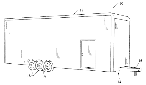
[00028] Figure 1 is a perspective view of a trailer employing an embodiment of
a
frame of the present invention;
[00029] Figure 2 is a perspective view of the top front end of the trailer
frame of the
present invention removed from the trailer;
[00030] Figure 2A is a close up perspective view of the area indicated in
Figure 2 of
an A-frame member intersecting one of the main beams;
[00031] Figure 3 is a top plan view of the front portion of the trailer frame
of Figure
2;
[00032] Figure 4 is a bottom perspective view of the trailer frame of Figure
2;
[00033] Figure 4A is a close up perspective view of the area indicated in
Figure 4 of
the A-frame member intersecting the main beam;
[00034] Figure 5 is a bottom plan view of the trailer frame of Figure 2;
[00035] Figure 6 is a side view of the trailer frame of Figure 2;
[00036] Figure 7 is a front view of the trailer frame of Figure 2;
[00037] Figure 8 is a perspective view of one of the main beams removed from
the
trailer frame;
[00038] Figure 9 is a cross-sectional view of the main beam of Figure 8 taken
along
line 9-9;
[00039] Figure 10 is a perspective view of one of the A-frame diagonal
members;
and
[00040] Figure I I is a perspective view of a rectangular cross beam at the
base of
the A-frame.
SBIMANI 192308v] -7-
CA 02487056 2004-11-05
[00041] Corresponding reference characters indicate corresponding parts
throughout the several views. Although the drawings represent an embodiment of
the
present invention, the drawings are not necessarily to scale and certain
features may be
exaggerated in order to better illustrate and explain the present invention.
The
exemplification set out herein illustrates an embodiment of the invention, in
one form, and
such exemplification is not to be construed as limiting the scope of the
invention in any
manner.
DETAILED DESCRIPTION OF EMBODIMENTS OF THE INVENTION
[00042] For the purposes of promoting an understanding of the principles of
the
invention, reference will now be made to the embodiments illustrated in the
drawings,
which are described below. It will nevertheless be understood that no
limitation of the
scope of the invention is thereby intended. The invention includes any
alterations and
further modifications in the illustrated devices and described methods and
further
applications of the principles of the invention which would normally occur to
one skilled
in the art to which the invention relates.
[00043] Referring now to Figure 1, a towable trailer is shown generally
indicated as
10. Towable trailer 10 is designed and configured to be pulled by a tow
vehicle (not
shown) for transporting the trailer and any cargo contained therein to a
desired location.
Trailer 10 includes a trailer body generally indicated as 12 including a deck,
and a trailer
frame generally indicated as 14. Trailer frame 14 includes an A-frame or
frontal extension
generally indicated as 16 for use in hitching trailer 10 to the tow vehicle
and for
supporting the front of the trailer when parked. Providing rolling movement to
the trailer
is a set of wheels 18 having axles 19, which are connected to frame 14.
[00044] Referring now to Figures 2-7, the front portion of trailer frame 14
and A-
frame 16 are depicted in greater detail. A line break is provided between the
front portion
of trailer 14 and the rear portion to indicate that the subject invention may
be used with
trailers of any length. In addition, a portion of trailer frame 14 is depicted
in phantom
lines as this portion of the trailer is well known.
[00045] Trailer frame 14 includes a pair of main support frame members 20 that
extend along the longitudinal direction of trailer 10. Trailer frame 14 also
includes a
SBIMANI 192308v] -8-
CA 02487056 2004-11-05
plurality of cross frame members 22, a front cross frame member 24, and a base
cross
frame member 26 located at the base of A-frame 16. Located to the outside of
main
support frame members 20 are side rails 28a, 28b and side rail supports 30.
[00046] A-frame 16 includes a pair of diagonal extension frame members 32 with
one end of each diagonal frame member mounted to a respective main support
frame
member 20. The opposite ends of diagonal extension frame members 32 converge
to a
hitch point generally indicated as 34. A-frame 16 also includes a central
longitudinally
extending extension frame member 36 spaced between diagonal extension frame
members
32 and attached to base cross frame member 26. Sandwiching the extension frame
members at hitch point 34 are a pair of triangular shaped plates 38.
[00047] Referring now to Figures 8 and 9, in the embodiment depicted, it can
be
seen that main support frame members 20 include an I-beam 40. I-beams 40
include an
upper flange 42 that defines a deck side 43 of trailer frame 14, a lower
flange 44 that
defines a bottom side 45 of trailer frame 14, and a web 46 extending
transversely between
the flanges. Main support frame members 20 also each include a plate member 48
attached to and extending between inner edges of upper flange 42 and lower
flange 44 on
each I-beam. Plate member 48 is attached to the flanges using a known method
such as by
welding. Plate 48 may also be attached to the outer ends of the upper and
lower flanges as
opposed to between them as shown.
[00048] Referring now to Figure 10, in the embodiment shown, diagonal
extension
frame members 32 have a tubular rectangular configuration. One end 50 of the
diagonal
extension members is angled for joining the extension frame members at hitch
point 34.
The other end 52 of diagonal extension frame members 32 is notched. The
diagonal
extension frame members 32 also each include an upper side 54 and a lower side
56. The
notched end 52 of the extension frame members is also angled, but at a
direction opposite
that of angled end 50 as shown in Figure 10, and the notched end includes a
projection 58
extending from lower side 56.
[00049] Referring now to Figure 11, base cross frame member 26 has a pair of
notched ends 60, 62. Notched ends 60, 62 are not angled as notched ends 52 of
diagonal
extension frame members 32 as the base cross frame member is mounted
transversely to
main support frame members 20 instead of at an angle as diagonal extension
frame
members 32. Base cross frame member 26 has a rectangular tubular configuration
in the
SB Rv7AN 1192308v ] -9-
CA 02487056 2004-11-05
embodiment shown and includes an upper side 64 and a lower side 66. A pair of
projections 68, 70 extend from base cross frame member 26 at notched ends 60,
62,
respectively, along lower side 66.
[00050] In the-embodiment of trailer frame 14 shown, central longitudinal
extension
frame member 36 also has a rectangular tubular configuration as does the front
cross
frame member 24. The remainder of cross frame members 22 and side rail
supports 30 of
trailer frame 14 have a C-channel configuration, while side rails 28, 28b have
an L-shaped
configuration and are commonly referred to as angle members.
[00051] To assemble trailer frame 14, the frame members are typically welded
to
one another as is well known in the industry. Plate members 48 serve as the
attachment
points for diagonal extension frame members 32 and base cross frame member 26.
This
design provides a mounting configuration similar to mounting to a box
structure as
opposed to mounting the members to the contours of I-beams. In addition, the
design
allows for base cross frame member 26, diagonal extension frame members 32,
and central
longitudinal extension frame member 36 to be assembled so that upper sides
thereof are
approximately flushed to deck side 43 of main support frame members 20. This
facilitates
the installation of the trailer deck on the trailer frame in a level and firm
manner.
[00052] Projection 58 on the end of diagonal extension frame members 32
overlaps
the respective bottom side 45 of lower flange 44 of the main support frame
members.
Likewise, projections 68 and 70 on base cross frame member 26 also overlaps
the
respective bottom side 45 of lower flange 44 of the main support frame
members.
Configured in this manner, the upper portion of notched ends 52, 60 and 62 are
welded or
otherwise attached in a known manner to the respective plate members 48, while
projections 58, 68, and 70 are welded or otherwise attached in a known manner
to
respective lower flanges 44 of main support frame members 20.
[00053] It should also be realized that in the embodiment shown, front cross
frame
member 24 and the cross frame members 22 forward of base cross frame member 26
must
either be cut and welded to diagonal extension frame members 32 and central
longitudinal
extension frame member 36 at the intersecting points, or holes may be cut in
diagonal
extension frame members 32 and central longitudinal extension frame member 36
to
accommodate cross frame members 22 and front cross frame member 24.
SBIMAN 1 192308v] -10-
CA 02487056 2004-11-05
[00054] While the invention has been taught with specific reference to the
above
described embodiment, one skilled in the art will recognize that changes can
be made in
form and detail without departing from the spirit and scope of the invention.
For example,
although specific structural configurations have been identified for the
various members of
trailer frame 14, any suitable structural configuration may be substituted for
those
described. In addition, although trailer frame 14 has been shown with two main
support
frame members 20, additional main support frame members may be utilized. Also,
main
support frame members may be other than parallel to one another as is also
true with cross
frame members 22, front cross member 24, base cross frame member 26, and side
rail
supports 30. Further, additional diagonal extension frame members 32 and/or
central
longitudinal extension frame members 36 may also be employed to provide
additional
structural rigidity. As such, the described embodiment is to be considered in
all respects
only as illustrative and not restrictive. The scope of the invention is,
therefore, indicated
by the following claims rather than by the description.
SBIMANI 192308v1 -1 1-