Note: Descriptions are shown in the official language in which they were submitted.
CA 02487082 2004-11-05
DISHWASHER HAVING A SIDE-BY-SIDE RACK SYSTEM
BACKGROUND OF THE INVENTION
1. Field of the Invention
The present invention pertains to the art of dishwashers and, more
particularly, to a dishwasher having a side-by-side rack system defining
multiple washing zones.
2. Discussion of the Prior Art
In general, dishwashers having multiple dish supports or rack
assemblies are known in the art. Particularly, it is known to provide
upper and lower rack assemblies, as well as upper, side-by side rack
assemblies which are cantilevered from opposing side walls, in a front-
loading dishwasher. However, as modern kitchens expand in size,
consumers are finding a need for wider dishwashers. With these wider
designs, cantilevering a rack assembly off a side wall limits the weight
1
CA 02487082 2004-11-05
that can be supported at any given time. Moreover, consumers, while
also demanding larger capacity dishwashers, desire a more efficient
method to wash smaller quantities of dishware.
As kitchens expand in size, the need for space-efficient appliances
is rapidly becoming a thing of the past. Kitchen island systems and larger
countertops all provide ample space for wider, larger capacity,
appliances. In particular, the demand for larger capacity dishwashers is
on the rise. The accumulation of breakfast and dinner dishes is typically
more than can be accommodated in a single load. In today's fast-paced
to society, consumers do not have the time~to run numerous loads of
dishware each day. Additionally, as consumers often need a dishwashing
appliance to clean extra load loads resulting from entertaining friends and
family. Otherwise, a consumer may be required to run a dishwasher
multiple times in order to handle the large quantity of dishware
accumulated during a party.
If manufacturers were to gear up to fabricate larger capacity
appliances and, in particular, wider dishwashers, they would be faced
with the problem of dish support or rack size. Designing racks which are
sized to fit into wider units would require retooling production facilities
2o and, with a wider footprint, the size of the production line must be
expanded. In many cases, in order to accommodate the larger production
lines, new buildings must be constructed. The large capital outlay
associated with new production facilities, as well as new production lines
is typically more than most manufactures are willing to risk on a new,
untested product line.
2
CA 02487082 2004-11-05
Finally, in addition to demanding more capacity, energy efficiency
is high on the list of consumer priorities. Operating a large capacity
dishwasher with only a small load inside is certainly inefficient. Without
the ability to control the amount of wash water or focus the water flow to
efficiently perform a washing operation, consumers will have to wait to
load the dishwasher to its full capacity. While generally not a problem,
oftentimes it is necessary to wash only a relatively few dishes at the end
of a day. In this case, without the ability to control the wash operation,
the consumer may put off washing dishes until enough have accumulated
to to make operating the dishwasher practical.
Based on the above, there exists a need in the art for a large
capacity dishwasher having a wider footprint. More particularly, there
exists a need for a large capacity dishwasher having a side-by-side rack
system which utilizes both existing dish rack systems arranged alongside
a narrower rack system to reduce production costs. Finally, there exists a
need for a dishwasher that can selectively direct a washing action to
either one, the other or both of the rack systems in order to increase the
efficiency of the appliance.
SUMMARY OF THE INVENTION
2o The present invention is directed to a dishwashing appliance
having a side-by-side rack system. More specifically, the dishwashing
appliance includes a cabinet shell, a tub defining a washing chamber, and
a door assembly pivotally mounted to the cabinet shell for selectively
sealing the central cavity. In accordance with a preferred arrangement,
3
CA 02487082 2004-11-05
slidably supported within the washing chamber are first and second side-
by-side dish support racks. In one preferred embodiment, the first rack is
a standard 20-inch (50.8-cm) dish rack as used in a standard 24-inch
(60.96-cm) wide dishwasher, while the second rack is sized substantially
s smaller having, for example, a 7-inch (17.78-cm) width. With this
arrangement, positioned side-by-side, a 32-inch (81.28-cm) wide
dishwasher is formed. In an even more preferable arrangement, the
dishwashing appliance includes a first rack system including first and
second upper dish support racks positioned over a second rack system
1 o having first and second lower dish support racks.
In an effort to increase the support capacity for each of the first and
second upper racks, a plurality of upper support elements are arranged
within the central cavity. More specifically, each of the upper support
elements includes a horizontally extendable outer rack support and an
15 intermediate, horizontally extendable rack support secured to an
intermediate support wall. Therefore, a pair of intermediate rack supports
are provided to engage with inner portions of the first and second upper
racks respectively. With this arrangement, each of the upper racks is not
cantilevered off of side portions of the central cavity, but is fully
2o supported along opposing sides thereof. Actually, the intermediate
member serves a dual purpose. That is, not only does the intermediate
member provide support for the upper racks, it also partially divides the
dishwasher into first and second wash zones.
In addition to the upper racks, first and second lower racks are
25 preferably supported through outer lower rack supports extending along
inner side walls of the washing chamber and an intermediate lower rack
4
CA 02487082 2004-11-05
support that extends across the washing chamber from a rear wall to a
front edge portion. Actually, a portion of each of the lower rack supports
is carried by the door assembly such that the door assembly includes
corresponding outer and intermediate rack supports.
Arranged proximate to each of the first and second rack systems is
a corresponding spray arm that provides a pressurized spray of washing
fluid to perform a washing operation in each of the first and second wash
zones. In a preferred arrangement, the first wash zone includes a rotating
spray arm positioned beneath each of the upper and lower first racks.
Correspondingly, the second wash zone includes a rotating spray arm or
wand positioned beneath each of the upper and lower second racks. In
the most preferred arrangement, a control can be used to selectively
supply pressurized wash fluid to the spray arms associated with each of
the first and second wash zones either singly or collectively. In this
manner, a consumer can choose to wash dishware loaded in either one or
both of the first and second wash zones.
Additional objects, features and advantages of the present
invention will become more readily apparent from the following detailed
description of a preferred embodiment when taken in conjunction with
the drawings wherein like reference numerals refer to corresponding parts
in the several views.
5
CA 02487082 2004-11-05
BRIEF DESCRIPTION OF THE DRAWINGS
Figure 1 is a front perspective view of a dishwashing machine
incorporating a side-by-side rack system constructed in accordance with
the present invention;
Figure 2 is a partial front elevational view of the dishwashing
machine of Figure 1, illustrating a preferred arrangement of the side-by-
side rack system of the present invention with a door of the dishwashing
machine removed;
Figure 3 is an upper left perspective view of the dishwashing
1 o machine and side-by-side rack system of Figure 2; and
Figure 4 is an upper left perspective view of the dishwashing
machine of Figure 3 with two of the racks being extended from the
dishwasher.
DETAILED DESCRIPTION OF THE PREFERRED
1 s EMBODIMENT
With initial reference to Figure l, a dishwasher 2 is generally
indicated to be positioned below a kitchen countertop 5. In accordance
with a preferred form of the invention, while standard dishwashers
generally are constructed to have approximately a 24-inch (60.96-cm)
20 width, dishwasher 2 is wider, and actually has a width of approximately
32-inches (81.28-cm). Also below kitchen countertop 5 is shown
6
CA 02487082 2004-11-05
cabinetry 8, including a pair of drawers 10 and 11, and lower cabinet
doors 13 and 14. Dishwasher 2 includes a door 17, including an inner
panel (not separately labeled), pivotally mounted to a cabinet frame
member 19. Dishwasher 2 is also shown to include a control panel
portion 24. In the embodiment illustrated, control panel portion 24
includes a display 27, a row of control buttons 29 and a vent zone 33. In
general, this overall arrangement of dishwasher 2 and countertop 5 is
known in the art wherein dishwasher door 17 is adapted to extend across
and close an access opening sealing a tub or washing chamber 35
1 o associated with dishwasher 2, while also being pivotal, such as through a
latched handle 39, to a position which enables loading and unloading of
dishwasher 2. As shown in Figure 2, washing chamber 3 S includes an
upper wall 42, lower wall 43, opposing side walls 44 and 45 and a rear
wall 46.
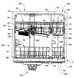
Referring to Figures 2-4 depicting a preferred form of the
invention, dishwasher 2 includes a first dish support rack system
indicated generally at 60. First dish support rack system 60 includes first
and second upper racks 62 and 63. First rack 62 preferably has a first
width of about 20-inch (50.8-cm) which fits the width of a standard
dishwasher, which for example is 24-inches (60.46 cm), and second rack
63 has a second width, substantially narrower than the first dish rack 62,
preferably approximately 7-inches (17.78 cm). As shown, each of first
and second upper racks 62 and 63 is slidably supported within washing
chamber 35. Towards that end, first dish support rack system 60 is
provided with upper and lower outer bearing elements or rollers 67 and
68, as well as upper and lower inner bearing elements. or rollers 70 and 71
for first upper rack 62. Similarly, first dish support rack system 60 is
7
CA 02487082 2004-11-05
provided with upper and lower inner bearing elements or rollers 74 and
75, as well as upper and lower outer bearing elements or rollers 77 and 78
for second upper rack 63.
In addition, first dish rack support system 60 is provided with a
plurality of horizontally extendable rack support guide rails adapted to be
movably supported by bearing elements 67, 68, 70, 71 and 74, 75, 77, 78
carried by first and second upper racks 62 and 63 respectively. More
specifically, as best shown in Figure 2, first upper rack 62 is mounted to
an outer rack support and guide rail 84 which extends between bearing
1o elements 67, 68 and to an inner rack support rail 85 arranged between
bearing elements 70, 71. In a similar manner, second upper rack 63
carries an inner rack support rail 88 extending between bearing elements
74, 75 to an outer rack support rail 89 arranged between bearing elements
77, 78. Actually, each of bearing elements 70, 71, 74 and 75 is mounted
for rotation to an intermediate support structure or wall 95 which extends
downward from upper wall 42 and forward from rear wall 46. With this
construction, each of first and second upper racks 62, 63 is fully
supported within dishwasher 2 for sliding movement into and out of
washing chamber 35 for loading and unloading dishware thereupon.
2o In accordance with the most preferred form of the invention,
dishwasher 2 is also provided with a second dish support rack system
indicated generally at 100. As shown, second dish support rack system
100 includes first and second lower dish racks 103 and 104 that actually
define third and fourth dish racks arranged within dishwasher 2. Each of
first and second lower dish racks 103 and 104 is supported by a plurality
of bearing elements or rollers which, in the most preferred form of the
s
CA 02487082 2004-11-05
invention, take the form of wheel assemblies 108 and 109. More
specifically, first lower dish rack 103 is provided with a plurality of outer
wheel assemblies 108 and inner wheel assemblies 109. Similarly, second
lower dish rack 104 includes a plurality of inner wheel assemblies 112
and outer wheel assemblies 113. Of course, it should be understood that
each of wheel assemblies 108, 109, 112 and 113 is secured to an
associated axle (not labeled) projecting from a respective one of first and
second lower racks 103 and 104.
In accordance with the invention, first and second lower racks 103
1 o and 104 glide upon a plurality of lower rack support elements. More
specifically, the lower rack support elements are defined by first and
second outer rack support guides 134, 135 and an intermediate support
guide 137. As best seen in Figures 3 and 4, intermediate guide 137
extends from rear wall 46 to a front edge portion of cabinet frame
member 19. In the embodiment shown, intermediate guide 137 is
provided with an upstanding projecting wall or divider 140 which
separates the intermediate guide 137 into first and second glide flats or
paths 142 and 143 which provide support for bearing elements 109 and
112 of first and second lower racks 103 and 104 respectively.
Actually, in the most preferred form of the invention, the plurality
of lower rack support guides 134, 135 and 137 discontinuously extend
onto door 17. As best seen in Figure 3, arranged upon door 17 are first
and second outer rack support guides 148 and 149, each having a
respective glide path 152, 153. Also shown in Figure 3 is an intermediate
support guide 157 which, in a manner analogous to intermediate guide
137, includes an upstanding wall or divider 160 separating intermediate
9
CA 02487082 2004-11-05
support guide 157 into first and second glide flat paths 162 and 163.
With this arrangement, first and second lower racks 103 and 104 can be
withdrawn from washing chamber 35 and allowed to rest upon door
assembly 17 to enable a consumer to load dishware into or remove
dishware from dishwasher 2. Furthermore, in accordance with one aspect
of the invention, first and second lower support racks 103 and 104 are
provided with separate upstanding support structure (not separately
labeled) which provide additional support for taller items such as baking
pans and the like.
1 o Having described the preferred structure of dishwasher 2,
reference will now be made to Figures 1-4 in describing a preferred
method of operation. Dishwasher 2 is provided with a controller or CPU
182 (Figure 1) which is adapted to receive inputs through the row of
control buttons 29 to establish a particular washing operation. In
1 s accordance with the most preferred form of the invention, dishwasher 2 is
divided into first and second independently controllable wash zones 186
and 187, as best seen in Figure 2. That is, first wash zone 186 is
constituted by first upper rack 62 and first lower rack 103, and s~ond
wash zone 187 is constituted by second upper rack 63 and second lower
2o rack 104.
As best seen in Figure 3, first wash zone 186 is provided with an
upper spray arm 192 positioned below first upper rack 62 and a
corresponding lower spray arm 193 arranged below first lower rack 103.
In the embodiment illustrated, upper spray arm 193 interconnects to
25 outlet portions (not separately labeled) of a manifold 199. Actually,
manifold 199 includes first and second upper outlet portions (not
to
CA 02487082 2004-11-05
separately labeled) that accommodate a vertical height adjustment for
first upper dish rack 62. However, as the actual construction and
operation of this height adjustment arrangement does not constitute part
of the present invention, it will not be discussed further here, but is set
forth in greater detail in commonly assigned U.S. Patent Application
Serial No. 10/186,739 entitled "Dishwasher Pump and Filtration System"
which is incorporated herein by reference.
In a corresponding fashion, second wash zone 187 is provided with
a respective upper spray arm 203 and lower spray arm 204 extending
from an auxiliary conduit or manifold 209. In further accordance with
this form of the invention, upper and lower spray arms 203 and 204 are
constituted by rotary wands which provide a pressurized spray directed at
upper dish rack 63 and lower dish rack 104 respectively. In any event,
pressurized fluid provided by a pump 210 is selectively directed into each
of manifolds 199 and 209 to perform a respective washing operation.
In further accordance with the most preferred form of the
invention, controller 182 can be selectively set to activate first and second
wash zones 186 and 187 either singly or concurrently in order to perform
a washing operation. With this construction, a consumer can load dishes
into either or both of dish support racks provided in first and second wash
zones 186 and 187. In this manner, a consumer can make the most
efficient use of dishwasher 2 and, if only a small number of dishes and/or
relatively few dishware items require washing, reduce energy
consumption by limiting a washing operation to just second wash zone
187.
11
CA 02487082 2004-11-05
Although described with reference to a preferred embodiment of
the present invention, it should be readily apparent to one of ordinary
skill in the art that various changes and/or modifications can be made to
the invention without departing from the spirit thereof. For instance,
while intermediate support 95 is depicted as a wall, an open structure
would also be acceptable. In addition, the dish rack support system could
take on various forms such as roller bearings, extensible arms and the
like. Also, additional spray arm could be positioned above the upper
racks to direct a washing fluid downward onto the dishware. In general,
1 o the invention is only intended to be limited to the scope of the following
claims.
12