Note: Descriptions are shown in the official language in which they were submitted.
CA 02487237 2006-01-31
Cyl.indrical Drum with Sanding Elements
FIELD OF THE INVENTION
The present invention concerns a cylindric drum for a sanding/polishing tool
which in
its drum surface is provided with a number of undercut axial grooves for
mounting
one or more axially displacing sanding elements.
BACKGROUND OF THE INVENTION
By using cylindric drums for sanding/polishing tools having undercut and
through-
going grooves in the surface of the cylindric drimn, thus enabling fitting and
replacing
sanding elements sliding longitudinally, it is necessary that the
longitudinally displac-
ing sanding elements are held in place during use of the sanding/polishing
tool.
Normally, at one end of the cylindric drum there will be an arrangement with a
plate
and a means for fastening the cylindric drum to a drive unit, e.g. a gearbox
andlor a
motor. At the other end of the cylindric dnmi there will be a second
arrangement with
a releasable plate and possibly a means for fastening the cylindric drum to a
support
unit.
However, this has the drawback that in order to replace the sanding elements
in the
cylindric drum, the arrangement with the releasable plate has to be taken
apart, which
may be cambersome and time-consuming.
SUMMARY OF THE INVENTION
It is therefore an object of the invention to provide a cylindric drum that
enables
secure retention of the longitudinally displacing sanding elements during use.
of the
sanding/polishing tool and which by replacement of the sanding elements is
easfly and
rapidly operated.
This may be achieved with a cylindric drum being characterised in that an
annular
groove has been provided either in the drum surface or a shaft perpendicularly
to the
rotational axis of the cylindric drum and along the periphery of either the
surface of
:. ~
CA 02487237 2006-01-31
2
the drum or the surface of the shaft, that a stop means has been arranged for
accom-
modation in the annular groove in an axially fixed position, where at least a
part of the
stop means abuts on end faces of the mouldings of the sanding elements mounted
in
the axial undercut grooves.
Alternatively, this may be achieved with. one cylindric drnm being
characterised in
that there is provided an elastic means with bearing against the drum surface
or the
shaft surface and preferably perpendicularly to the rotational axis of the
cylindric
drum and along the periphery of either the drum surface or the surface of the
shaft,
where at least a part of the elastic means abuts on a part of the mouldings of
the sand-
ing elements that are mounted in the axial, undercut grooves.
In order to achieve securing of longitudinally displacing mouldings in the
undercut
axial grooves in the cylindric dram, the drum is designed with an annular
groove per-
pendicularly to the rotational axis of the cylindric drum and along the
periphery of
either the drum surface or the shaft surface in which it is possible to
provide a stop
means arranged'to be accommodated in the annular groove in an axially fixed
posi-
tion. As at least a part of the stop means is in contact with end faces of the
sanding
element mouldings mounted in the axially undercut grooves, these cannot move.
If the annular groove is disposed in the drum surface, it will cross all the
undercut ax-
ial grooves in the drum surface, and the sanding elements are adapted so that
they
have a length corresponding to the length from one end of the cylindric drum
and to
the undercut groove.
If the annular groove is disposed in the surface of the shaft of the cylindric
drum, it
will be in immediate continuation of all the undercut axial grooves, and the
sanding
eleinents are adapted so that they have a length corresponding to the length
of the cyl-
indric dram.
In an alternative embodinient, there will only be provided two annular grooves
per-
CA 02487237 2004-11-05
WO 03/095148 PCT/DK03/00297
3
pendicularly to the cylindric shaft and along the periphery, either in
immediate vicin-
ity of each end of the drum surface, or in the shaft surface at each side of
the cylindric
drum.
In order to achieve secure fastening of the sanding elements, the stop means
and the
annular groove are designed so that the stop means by disposition in the
annular
groove are secured in axial direction.
Depending on how the annular groove has been designed and which stop means
used,
there are two possibilities: either an annular groove with stop means filling
the entire
annular groove, or an annular groove with a stop means filling the annular
groove and
extending outside the annular groove.
The most important concerning the stop means is, however, that at least a part
of it is
abutting on the end faces of the mouldings of the sanding elements. This
provides that
the shape and depth of the annular groove is depending on which type of stop
means is
used.
In one embodiment, the stop means is an elastic device, where the elastic
device is e.g.
an 0-ring and/or a lock ring.
The elastic 0-ring is preferably made of rubber, but may alternatively be made
of plas-
tic material, a metal alloy and/or a textile. The only requirement is that the
0-ring by
placing in the annular groove is to tighten around the atmular groove so that
it is se-
cured during rotation of the cylindric drum, and it is possible to expand the
0-ring
sufficiently enough that it may be removed from the annular groove when a
replace-
ment of the sanding elements is to take place.
If the stop means is an elastic lock ring, this has to be designed so that it
is possible to
expand the lock ring so much that it may be mounted and dismounted in the
annular
groove. The lock ring may typically be made of spring steel, or another metal
alloy
and/or plastic mixture having resilient action.
CA 02487237 2004-11-05
WO 03/095148 PCT/DK03/00297
4
If further space may be provided in the longitudinal direction of the
cylindric drum, a
replacement of the mouldings may take place, while the cylindric drum is
suspended
between a drive unit and a possible support unit.
Alternatively, in an embodiment there may be used a strap which is placed and
clamped in the annular groove. In order to replace the longitudinally
displacing sand-
ing elements, the strap may typically be broken. This provides that the strap
is to be
produced inexpensively and not be complicated. This strap may e.g. be a clamp,
a rub-
ber band, a cord, and/or a strip.
In an alternative embodiment for retaining the sanding element moulds, the
cylindric
drum is designed so that the cylindric drum for a sanding/polisliing tool is
provided in
its drum surface with a number of undercut axial grooves for mounting one or
more
axially displacing sanding elements, and where there is provided an elastic
means with
bearing against the dr-um surface or the shaft surface and preferably
perpendicularly to
the rotational axis of the cylindric drum and along the periphery of either
the drum
surface or the surface of the shaft, where at least a part of the elastic
means abuts on a
part of the mouldings of the sanding elements that are mounted in the axial,
undercut
grooves.
This embodiment of the cylindric drum will be applied when using
sanding/polishing
tools einploying cylindric drums with large diameter and/or have significant
length.
Instead of making the cylindric drum with a groove, it will be easy to use an
elastic
means which by means of an axial contraction, elasticity and friction will
retain the
moulds of the sanding elements in the undercut grooves in the cylindric drum.
If the elastic means is disposed on the drum surface, it will be placed in
immediate
vicinity of the end which is not coupled to a drive unit.
If the elastic means is disposed on the shaft surface, it will be placed in
immediate
vicinity of the outlet from the axial undercut groove in the cylindric drum,
so that at
CA 02487237 2006-01-31
least a part of the elastic is abutting on the end face on the sanding element
moulds
that are mounted in the axial undercut grooves.
The elastic means may e.g. be one or more of the following: an elastic band, a
rubber
band and/or a textile. However, by mounting on the drum surface or the shaft
surface
it is to provide axial contraction so that the elasticity and the friction may
retain the
sanding element moulds in the undercut groove of the cylindric drum without
they
being provided a longitudinally displacing movement.
According to an aspect of the present invention there is provided a cylindric
drum for
a sanding/polishing tool which in its drum surface is provided with one or
more
undercut axial grooves for mounting one or more axially displaceable sanding
elements having moldings, each sanding element comprising a molding adapted
for
mounting in one of the one or more undercut axial grooves, wherein an annular
groove has been provided either in the drum surface or a shaft perpendicularly
to the
rotational axis of the cylindric drum and along the periphery of either the
surface of
the drum of the surface of the shaft, that a stop means has been arranged for
accommodation in the annular groove in an axially fixed position, where at
least a
part of the stop means abuts on end faces of the moldings of the sanding
elements
mounted in the one or more undercut axial grooves.
According to another aspect of the present invention there is provided a
cylindric
drum for a sanding/polishing tool which in its drum surface is provided with
one or
more undercut axial grooves for mounting one or more axially displacing
sanding
elements having moldings, each sanding element comprising a molding adapted
for
mounting in one of the one or more undercut axial grooves, wherein there is
provided
an elastic means with bearing against the drum surface or the shaft surface,
where at
least a part of the elastic means abuts on a part of the moldings of the
sanding
elements that are mounted in the one or more undercut axial grooves.
BRIEF DESCRIPTION OF TIIE DRAWINGS
The invention is explained in more detail below, by way of example, with
reference to
the drawings, in which:
Fig. 1 shows a sectional side view of a cylindric drum according to the
invention,
CA 02487237 2006-01-31
Sa
Fig. 2 shows a section of a cylindric drum according to the invention,
Fig. 3 shows a section of a cylindric drnm according to the invention, and
Fig. 4 shows a section of a cylindric dnnn according to the invention.
DETAILED DESCRIPTION OF EXEMPLARY EMBODIMENTS
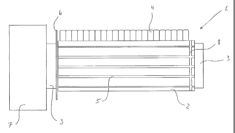
The perspective view shown in Fig. 1 of a cylindric drum I shows that a
cylindric
drum 1 includes a drum surface 2 and a shaft 3. On' the drum surface 2 there
are pro-
vided a number of undercut grooves 5 in which are mounted moulds (not shown)
with
sanding elements 4.
In the embodiment shown, a groove 8 is provided in the drum surface 2 in
vicinity of
the edge of the cylindric drum 1. The groove 8 is crossing all undercut axial
grooves 5.
One end of the cylindric drum is connected to an end plate 6 providing that
the moulds
(not shown) with the sanding elements 4 cannot be longitudinally displaced
further
than to the plate 6. In connection with the plate 6 and the shaft 3 there is
mounted a
drive unit 7. The opposite end of the cylindric drum 1 is shown as a free end
with a
projecting shaft 3. The cylindric drum and/or the shaft 3 may be connected to
a sup-
CA 02487237 2004-11-05
WO 03/095148 PCT/DK03/00297
6
port unit (not shown).
On Fig. 2 is shown a cross-section of the cylindric drum 1 in which an
undercut
groove 8 is crossing the axial groove 5. In the groove 8 is placed an 0-ring
11 acting
as a stop for axial movement of the mould 10. Iri the shown embodiment, the
shape of
the groove 8 is so that the 0-ring 11 is fitting into the groove 8 while the
upper part of
the 0-ring 11 is free of the groove 8.
As shown on Fig. 2 it is only a part of the 0-ring 11 which is used as stop
against the
movement of the mould 10 in the undercut groove 5. It is dependent on the
depth of
the groove 8 how great a part of the 0-ring 11 that is used for stop, but the
deeper
groove 8, the more difficult it may be to remove the 0-ring 11 from the groove
8.
On Fig. 3 is shown an alternative einbodiment for securing the longitudinally
displac-
ing moulds 10. Grooves 13 are provided in shaft 3 immediately opposite the end
piece
12 of the cylindric drum 1 so that an 0-ring 11 mounted in groove 13 forms a
stop for
the mould 10 in the undercut groove 5.
In this einbodiment it is important that groove 13 is designed so that the 0-
ring will
have a free part protruding up and covering a part of the mould 10, thereby
forming a
stop for longitudinally displacing movements.
On Fig. 4 is sllown a cross-section of a cylindric drum 1 with a drum surface
2, where
an elastic means 15 is provided for retaining the sanding element mould 10 and
which
by means of axial contraction, elasticity and friction retains the sanding
element
mould 10 in the undercut groove 5 of the cylindric drum 1.
The invention is not limited to the embodiments shown and described above in
the
Figures. Other embodiments including other embodiments of grooves and elastic
means are possible within the scope of this invention and the matter specified
in the
claims.