Note: Descriptions are shown in the official language in which they were submitted.
CA 02487467 2013-03-21
GAS-MEASURING DEVICE WITH AN ELECTROCHEMICAL
SENSOR
FIELD OF THE INVENTION
The present invention pertains to a gas-measuring device with an
electrochemical sensor.
BACKGROUND OF THE INVENTION
Electrochemical sensors, especially electrochemical gas sensors, usually do
not have an
unlimited service life. A point in time at which the technical properties are
no longer sufficient for
accomplishing the measuring task is reached at a certain time. In
electrochemical gas sensors, one
of these properties may be, for example, the level of the output signal at a
certain gas
concentration. Such sensors should therefore be exchanged and replaced with
new ones at certain
intervals.
Both a safety engineering aspect and an economic aspect play a role concerning
the point
1
CA 02487467 2004-11-15
in time at which the replacement is necessary. From a purely safety
engineering viewpoint, the
sensor would be replaced at the shortest possible intervals (for example,
yearly or more
frequently) in order to rule out a failure with the highest possible
probability. The drawback of
doing so is that needlessly high costs are incurred.
From a purely economical viewpoint, a sensor would be replaced only when it
was
recognized as being defective. This defect may be determined during the
calibration or also
during a sensor self-test. The drawback here is that the measuring function is
not guaranteed
continuously, because replacement of the sensor cannot always be carried out
in a short time.
A process for recognizing sources of error in amperometric measuring cells is
known from
DE 44 45 947 C2. The voltage of the potentiostat is slightly detuned here in
order to calculate
from this parameters that provide information on the state of use of the
electrochemical sensor. It
is displayed whether a sensor has been used up or damaged. However, the prior-
art process
provides no information on how long the sensor can still be used for
measurement purposes.
SUMMARY OF THE INVENTION
The basic object of the present invention is to improve a gas-measuring device
with an
electrochemical sensor such that the readiness for use is guaranteed over a
predetermined period
of time.
According to the invention, a gas-measuring device is provided with an
electrochemical
2
CA 02487467 2004-11-15
sensor. An evaluating circuit is provided for processing sensor-specific
measured variables. A
status display is provided that is activated by the evaluating circuit for
displaying the sensor
depletion.
The advantage of the present invention is essentially that a status display,
which displays
the degree of depletion of the sensor to the user, is generated at the gas-
measuring device on the
basis of sensor-specific measured variables. The user thus obtains information
on the optimal
point in time for the replacement of the sensor. The measuring function of the
gas sensor can thus
be utilized over the longest period of time possible. The status display
described in the present
invention is not limited to electrochemical sensors, but it can also be used
in case of catalytic or
optical gas sensors or electrochemical systems such as batteries.
A trend curve is advantageously determined as a function of time in the
evaluating circuit
as a function of sensor-specific measured variables and compared with a
predetermined limit
value. The status display is activated when the function value of the trend
curve has reached a
predetermined limit value. It is useful in this connection to set a plurality
of limit values, which
are associated with individual status displays. The course of the trend curve
can thus be followed
better.
The sensor current is suitable for use as the sensor-specific measured
variable in an
amperometric fuel cell, the trend curve being formed by integration of the
sensor current over
time. The value of the integral of a brand new sensor, hereinafter called the
current integral, is
3
CA 02487467 2013-03-21
zero. The depletion of the sensor is also zero here, i.e., the sensor is
suitable for use without
restrictions. The closer the current integral comes to a predetermined limit
value in the course of
the use of the sensor, the greater will be the depletion of the sensor up to
the complete
consumption of the electrolyte or the anode material.
The reduction of the sensor sensitivity E, which assumes the maximum in the
original state
and steadily declines during the use of the device, is suitable for use as an
alternative trend curve.
The sensor sensitivity can be determined, for example, during the calibration
cycles to be carried
out routinely, and a compensating straight line is drawn through the
individual measured values.
The decline in the sensor sensitivity E from the maximum to a predetermined
lower limit value is
an indicator of the depletion of the sensor or of the complete depletion of
the sensor.
A temperature sensor measuring the ambient temperature is expediently
provided, and
positive deviations and negative deviations from a mean temperature TM are
provided as
additional measured variables. Integrals of the positive temperature
deviations and negative
temperature deviations are then formed. The temperature sensor may be arranged
either at the
gas-measuring device itself or at the sensor.
According to one aspect of the present invention there is provided a gas-
measuring
device, comprising an electrochemical sensor; an evaluating circuit for
processing sensor-
specific measured variables, the evaluating circuit processing at least one
sensor-specific
measured variable to generate a trend curve over a lifetime of the sensor, the
measured variable
4
CA 02487467 2013-03-21
status display activated by the evaluating circuit for displaying a depletion
of the sensor as a
function of one of the sensor specific measured variables, and the status
display being activated
when the trend curve reaches predetermined limit values, the status display
providing three
indicators showing different degrees of depletion of the sensor, the
indicators being activated
when the trend curve reaches the predetermined limit values.
According to a further aspect of the present invention there is provided a gas-
measuring
system, comprising an electrochemical sensor; an evaluating circuit for
processing sensor-
specific measured variables, the evaluating circuit processing at least one
sensor-specific
measured variable to generate a trend curve over a lifetime of the sensor; and
a status display
activated by the evaluating circuit when the trend curve reaches a
predetermined limit value for
displaying a sensor depletion based on the processing of sensor-specific
measured variables, the
status display providing three indicators showing different degrees of
depletion of the sensor, the
indicators being activated when the trend curve reaches predetermined limit
values; an auxiliary
memory arranged at the electrochemical sensor and storing the trend curve, the
auxiliary member
and the sensor being separatable as a single unit from the evaluating circuit
and the status display
for use in other gas-measuring systems.
According to another aspect of the present invention there is provided a gas-
measuring
system comprising an electrochemical sensor; an evaluating circuit connected
to the sensor and
integrating current from the sensor, the evaluating circuit processing the
integrated current to
4a
CA 02487467 2013-04-02
,
,
=
calculate sensor depletion; a status display activated by the evaluating
circuit and displaying the
sensor depletion when the trend curve reaches predetermined limit values; a
temperature sensor
connected to the evaluating circuit and measuring ambient temperature, the
sensor having a
predetermined favorable operating temperature, the evaluating circuit
recording when the
ambient temperature is larger than the favorable operating temperature as
positive temperature
deviations, the evaluating circuit changing the limit values based on the
positive deviations.
Exemplary embodiments are shown in the drawings and will be explained in
greater
detail below. The various features of novelty which characterize the invention
are pointed out
with particularity in the claims annexed to and forming a part of this
disclosure. For a better
understanding of the invention, its operating advantages and specific objects
attained by its uses,
4b
CA 02487467 2004-11-15
reference is made to the accompanying drawings and descriptive matter in which
the preferred
embodiments of the invention are illustrated.
BRIEF DESCRIPTION OF THE DRAWINGS
Figure 1 is a schematic view of the design of a gas-measuring
device according to
the present invention;
Figure 2A is a view of one of different information states of a of
a status display;
Figure 2B is a view of another of different information states of a
status display;
Figure 2C is a view of another of different information states of a
status display;
Figure 2D is a view of another of different information states of
another status
display;
Figure 2E is a view of another of different information states of
the another status
display;
Figure 2F is a view of another of different information states of
the another status
display;
5
CA 02487467 2004-11-15
Figure 3A is an example of the evaluation of the sensor current
showing the course of
sensor current as a function of time;
Figure 3B is an example of the evaluation of the sensor current
showing the course of
the integral of sensor current;
Figure 4 is an example of the evaluation of the sensor sensitivity;
Figure 5A is an example for taking into account the temperature
effect showing the
course of the ambient temperature as a function of time; and
Figure 5B is an example for taking into account the temperature
effect showing the
integral of positive temperature deviations; and
Figure 5C is an example for taking into account the temperature effect
showing the
integral of negative temperature deviations;
DESCRIPTION OF THE PREFERRED EMBODIMENTS
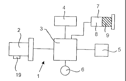
Figure 1 schematically illustrates a gas-measuring device 1 with an
amperometric fuel cell
as the sensor 2, an evaluating circuit 3 for processing sensor-specific
measured variables, a display
unit 4 for measured values of a power supply unit 5, a temperature sensor 6
and with a status
display 7 for the sensor depletion. The status display 7 has two display
fields 8, 9, which are
6
CA 02487467 2004-11-15
black or neutral depending on the state of the sensor. Only the display field
9 is blackened in the
sensor state shown in Figure 1, which approximately corresponds to a sensor 2
having been
consumed by more than half and still has a high readiness for use with low
failure probability.
Figures 2A-2E show different information states of the status display 7.
Figure 2D (the
left-hand view) shows two blackened display fields 8, 9 that represent an
unconsumed sensor 2
with a very high readiness for use and very low failure probability. In
contrast, Figure 2F (the
right-hand view of the status display 7) shows two unblackened display fields
8, 9 that illustrates a
sensor 2 that has only a limited readiness for use and should be replaced.
Figure 2E (the view in
the middle) corresponds to a sensor state that is between these two trend
values. As an
alternative, the status display may also be performed with symbols "good 10"
(Figure 2A),
"medium 11" (Figure 2B) and "poor 12" (Figure 2C).
One possibility of determining the depletion of the sensor is to form the
integral of the
sensor current as a function of time.
The upper part of Figure 3 illustrates the course of the sensor current as a
function of time
t; i = i(t). The time axis begins with t =0 for an unconsumed sensor 2. The
value of the sensor
current i(t) depends on the gas concentration to be measured. No gas to be
detected is present in
the middle range of the curve, and the sensor current i drops to zero. When
gas is admitted with
constant gas concentration, the sensor current i increases steadily in an
amperometric fuel cell
until the sensor 2 is consumed completely because of the electrochemical
reaction with the gas
7
CA 02487467 2004-11-15
sample.
The lower part of Figure 3 shows the course of the integral of the sensor
current i, the
current integral 18, as a function of the time t. The current integral 18
begins at the time t = 0
with zero value for a brand new, unconsumed sensor 2. A limit value G, at
which the sensor 2 is
consumed, is set for the current integral 18. This limit value G is determined
by experiments for a
certain type of sensor. Percentages of the limit values, 30% G and 75% G, are
set as the criterion
for the extent of the sensor depletion.
Both display fields 7, 8 of the status display 7 are blackened at the time t =
0 in case of an
unconsumed sensor 2. Only the display field 9 is active if the current
integral 18 reaches the limit
value 30% G at the time t = t1. When the 75% G limit value is exceeded at the
time t = t2, the
display field 9 goes out as well and the sensor 2 must be replaced.
As an alternative to the current integral 18 or in addition to the current
integral 18, the
sensor sensitivity E can be used as a criterion for the degree of depletion of
the sensor. The
sensitivity of the sensor is determined during calibration cycles to be
performed regularly and is
obtained from the quotient of the signal rise and the change in the gas
concentration.
Figure 4 illustrates the course of the sensor sensitivity E as a function of
the duration of
use t. The sensor sensitivity E is determined for the first time at the time t
= 0 for a brand new
sensor 2 and is set at 100%. Extrapolation lines are drawn through additional
measured values
8
CA 02487467 2004-11-15
13, 14, 15, 16 determined within the framework of calibrations. The
compensation line 17 shows
the decline of the sensitivity E as a function of the duration of use t. Only
40% of the original
sensitivity E is present at the time t = t1, whereas the sensitivity has
dropped to 30% of the initial
value at the time t = t2.
The sensor sensitivity E has its maximum at the time t = 0, and both display
fields 8, 9 of
the status display 7 are blackened. If the sensor sensitivity E has dropped to
40% E at the time t
= t1, only the display field 9 is active. If the sensor sensitivity E drops
below the value 30% E at
the time t = t2, none of the display fields 8, 9 is active, and the sensor 2
must be replaced.
If the sensor 2 is exposed to temperature effects, the ambient temperature
must be taken
into account for the evaluation of the depletion of the sensor.
Figures 5A - 5C show an example for taking into account the temperature
effect.
The upper curve (Figure 5A) illustrates the course of the ambient temperature
T as a
function of the time t. The temperature T., favorable for the operation of the
sensor is taken from
the sensor specification and used as a reference line for the temperature
evaluation. Positive
deviations, designated by "plus," and negative deviations, designated by
"minus," are integrated in
separate integrals as a function of time. Positive temperature deviations
usually shorten the
duration of use of the sensor 2 more greatly than do negative temperature
deviations.
9
CA 02487467 2004-11-15
The middle curve (Figure 5B) shows the integral of the positive temperature
deviations,
while the lower curve (Figure 5C) represents the integral of the negative
temperature deviations.
Factors that affect the determination of the status of the sensor are
determined from the
temperature integrals at the times t1 and t2. The higher the values of the
temperature integrals at
the times t1 and t2, the more greatly are the limit values reduced at which
the status display 7 with
two blackened 8, 9 jumps over to a blackened display field 9 or the display
for the sensor
replacement, for which case no display field 8, 9 is active, is reached
already earlier in time at the
corresponding times of the current integral 18 according to Figure 3B or the
compensating lines
17 for the sensor sensitivity E according to Figure 4. The status data of the
sensor 2 are stored in
an auxiliary memory 19 arranged at the sensor 2 in order to make it possible
to also determine the
status of the sensor 2 when this was used at different devices.
While specific embodiments of the invention have been shown and described in
detail to
illustrate the application of the principles of the invention, it will be
understood that the invention
may be embodied otherwise without departing from such principles